GENERAL DESCRIPTION AND OPERATION
M104
26
The Models 8257-A Tappers have built-in valving and are forward and retact stroke. Positioning of the spool valve is ac-
designed to automatically feed to a pre-set depth, trip and complished by actuating the “F” or “R” Button BleedValves,
return. located at the rear of the head.
The Models 8357-A Tappers are “thru-head” type and are
designedto operate in the forward and retract strokeswith the
useof external valving.
The following is a brief description of the various sectionsand
their function.
GEARING: The gearing for thesemodels is available in dou-
ble reduction planetary gearing assembly to provide three (3)
final spindle speeds.
The BUTTON BLEED VALVES exhaust air from the endsof
the spool valve, causing it to shift to the forward and retract
positions. Depressing the Button Bleed Valve marked “F”
shifts the spool valve to the forward feed position. When the --
drill reachesthe pre-set depth, the Stroke Adjustment Screw
will depressthe Button Bleed Valve marked “R”, this shifts
the spool valve to the retract position and retracts the piston
completing the cycle.
AIR MOTOR: The vane type air motor develops a minimum
of .4 horsepower. The motor will start within the first l/4 inch
of stroke and remain running thru the forward and retract
stroke, automatically shutting off upon completion of the cy-
cle.
The needletype FEED CONTROL VALVES regulate the flow
of air from the piston thus regulating the forward and retract
rate of feed of the piston. The Feed Control Valve marked
“F” regulatesthe forward feedrate of the piston and the Feed
Control Valve marked “R” regulates the retract feed rate of
the piston.
AIR PISTON: The air piston is of the double acting type, pro-
viding the forward and retract stroke movement. The piston
has an area of 2.0 square inches and develops approximately
170pounds of thrust with 90 p.s.i.g. at the piston inlet.
VALVE SECTION - Models 8357-A( ) : The valve sec-
tion housesthe needletype FEED CONTROL VALVE mark-
ed “SLOW FEED” located at top of the valve housing and
regulates the forward feed rate of the piston.
VALVE SECTION - Models 8257-A( ): The valve section
housesthe SPOOL VALVE, BUTTON BLEED VALVES and
the FEED CONTROL VALVES. The SPOOL VALVE is a
4-way bleed type valve used to port air to the piston for the
TOOL RETRACTED SIGNAL PORT - this port is located
in rear end of Piston Rod. The port is pressurized when the
motor starts and remains pressurized during the drilling cycle
until the motor shuts off when the unit is fully retracted.
.
MANUAL OPERATION OF MODELS
8257-A(
)
The Models 8257-A( ) are shipped from factory with the Housing.
MANUAL BLEED VALVE (24130)installed in the “F” port
at the rear of the Valve Housing. If the unit is to be operated Each time the BUTTON BLEED VALVE marked “F” is
manually; loosen the two (2) Screws(Y154-19)securing Cover depressedthe unit will start in the advancing (forward) mode.
(40313-)to the Valve Housing and removethe Cover. Remove The unit will continue to advance until the BUTTON BLEED
the Button Bleed Valve from the “F” port at the rear of the VALVE marked “R” hasbeendepressedsufficiently to retract
Valve Housing and remove the Pipe Plug (Y227-2-L) fromthe the unit. SeeSET-UP PROCEDURE, PAGE 4. Should an
“F” port at the top of the Valve Housing. Install the Button EMERGENCY RETRACT be desired, install an additional
Bleed Valve (24130)in the “F” port at the top of the Valve Button BleedValve in the “R” port at the top Valve Housing.
Housing and seal off the “F” port at the rear of the Valve The EmergencyButton Bleed Valve can beusedto immediate-
Housing using the Pipe Plug(Y227-2-L). Replace the Cover ly retract the unit in the event of a misaligned part or similar
(40313-)and tighten Screws(Y154-19)securing Cover to Valve situation.
REMOTE CONTROL OPERATION MODELS
8257-A(
)
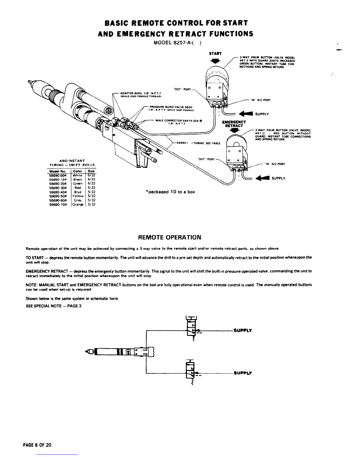
The Models 8257-A( ) can beusedasa single unit application REMOTE RETRACT is accomplished by use of a Pressure
or in a multiple unit application. REMOTE START is ac- BleedValve (part no. 9600)installed in the “R” port located at
complished by useof aPressureBleedValve (part no. 9600)in- the top of the Valve Housing. The valve is then connected to a
stalled in either the “F” port at the rear of the Valve Housing remote MANUALLY operated valve in the same manner as
or the “F” port in the top of the Valve Housing. This pressure the Remote Start circuit. This valve is used as an emergency
bleed valve is then connected, by meansof l/8” I.D. tubing, retract in the event of a part misalignment or similar situation
to a remote operated valve which, when actuated, feeds air only as the unit, when properly set-up and applied, will
pressure to the Pressure Bleed Valve (9600). The Pressure automatically retract and return to the start position after
Bleed Valve then opens, bleeding air from “F” port of Valve reaching a pre-setdepth or stroke. SeeSet-Up Procedure page
Housing, causing Spool Valve to shift to the Forward Feed 4 and illustration on page8.
position thus starting the advancing (forward) mode of the
unit.
REMOTE CONTROL OPERATION MODELS
8357-A( )
1
The Models 8357-A( )can beusedasa single unit application REMOTE RETRACT is accomplished by connecting, by use
or in a multiple unit application. REMOTE START is ac- of proper fittings and l/8” I.D. tubing, the “R” port at either
complished by connecting, by useof proper fittings and l/8” the top or at the rear of the Valve Housing to the same4-way
I.D. tubing, the “F” port at either the top or rear of the Valve valve the Remote Start circuit is connected. The 4-way valve is
Housing to a 4-way type valve which, when actuated, feedsair actuated once for the forward mode and actuated a second
pressureto the unit starting the advancing (forward) mode of time to retract the unit. The valve can be actuated at any time
the unit. after the unit has started the advancing (forward) mode to
retract the unit in the event of a part misalignment or similar
situation. Seeillustration on page9.
SPECIAL NOTE: The air inlet and remote ports of this tool have tapered pipe threads and should not require thread sealants,such
assealant tapesor pipe joint compound. Thread sealants used improperly can causevalve or tool malfunction.
FORM1661-2 PAGE3 OF20