9
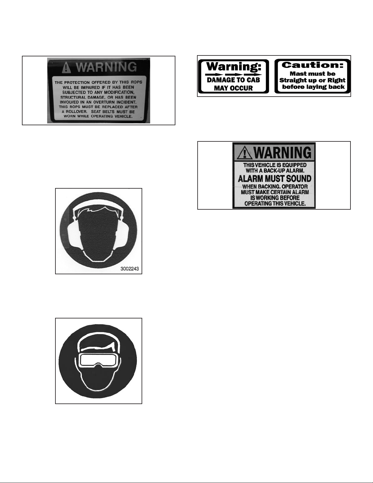
• Wear safety glasses or eye shields to protect from
dust and debris.
• Wear ear plugs to protect from loud or high pitched
noises.
• Wear gloves to protect hands from burns if hydraulic
components become hot during operation.
• Never wear sandals or other light footwear when
operating or servicing the machine. Wear protective
footwear when handling heavy parts.
• Do not wear loose tting clothing which may
become entangled when operating or servicing the
machine.
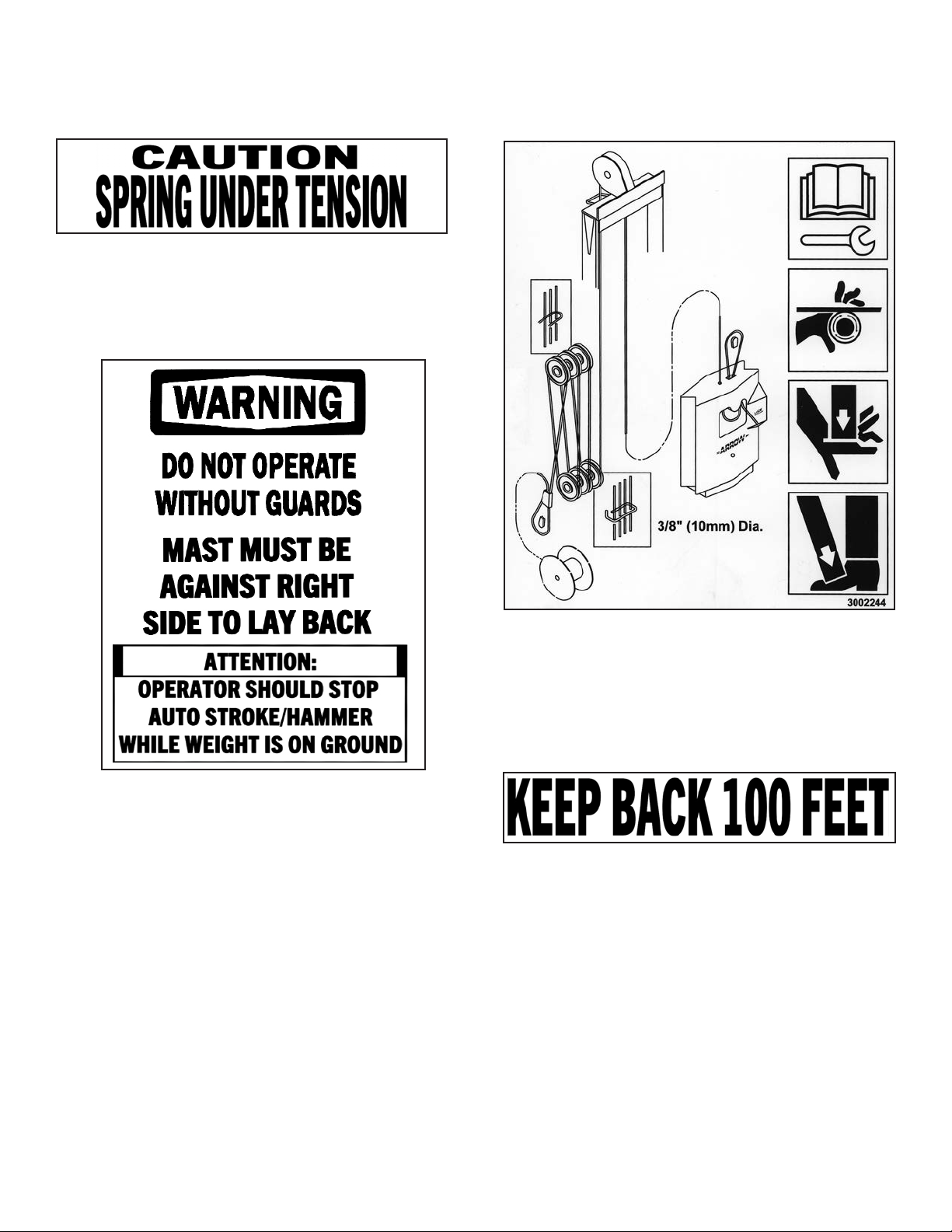
Parking Safely
1. Position the machine on level ground.
2. Fully shift the mast to the right.
3. Position the hammer and insert the hammer lock pin.
4. Fully lower the mast onto the mast rest and tilt the
mast to contact the ROPS (Roll-Over Protective
Structure).
5. Engage the park brake.
6. Turn the key switch to the OFF position and remove
the key from the switch.
• Do not allow anyone to operate the machine unless
they have rst read and understood the machine
operator manual.
• Do not allow anyone to operate the machine unless
they have rst read and understood the safety and
warning decals on the machine.
• The machine owner is responsible for training others
to safely operate the machine, and is responsible for
any injuries or harm which occurs while the machine
is being operated.
• Do not operate the machine inside enclosed areas
where carbon monoxide gas may build up.
• Before operating, replace any worn or damaged
safety decals.
• Before operating, thoroughly inspect the machine to
be sure all hardware (bolts, nuts, etc.) is installed and
tightened.
• Before operating, thoroughly inspect the machine
to be sure it is in working order. If the machine
is damaged or otherwise not in working order, do
not operate until it has been repaired by a qualied
technician.
• Do not operate the machine if you are under the in-
uence of alcohol, drugs, or medications which may
cause drowsiness.
• Do not allow children to operate the machine.
• Do not allow anyone who has not been trained to
operate the machine.
• Inspect the work area before operation to remove
any obstacles or mark them to avoid. Conrm no
lines or pipes or other objects are just beneath the
concrete surface.
• Conrm all guards are in place before operating.
• Keep hands, feet or other objects away from under-
neath the machine while operating.
• Never leave the machine unattended while the en-
gine is running.
• Position the machine on level ground or surface
when you are done operating.
• Allow the muer and engine to cool before touch-
ing.
• Keep the muer and engine area clean and free of
debris.
• Park the machine safely and disconnect the negative
battery terminal before performing any service.
• Do not allow anyone to service the machine unless
they have rst read and understood the machine
operator or service manuals.
• Do not allow anyone to service the machine unless
they have rst read and understood the safety and
warning decals on the machine.
• The machine owner is responsible for training others
to safely service the machine, and is responsible for
any injuries or harm which occurs while the machine
is being serviced.
• Always securely block the machine after raising to
inspect or service the machine.
Safety