eSTOP™ User Manual
Arrow Emergency Systems | 17 Bailey Court Brendale Q 4500 | P: (07) 3881 3302 | www.arrowes.com.au Page | 3
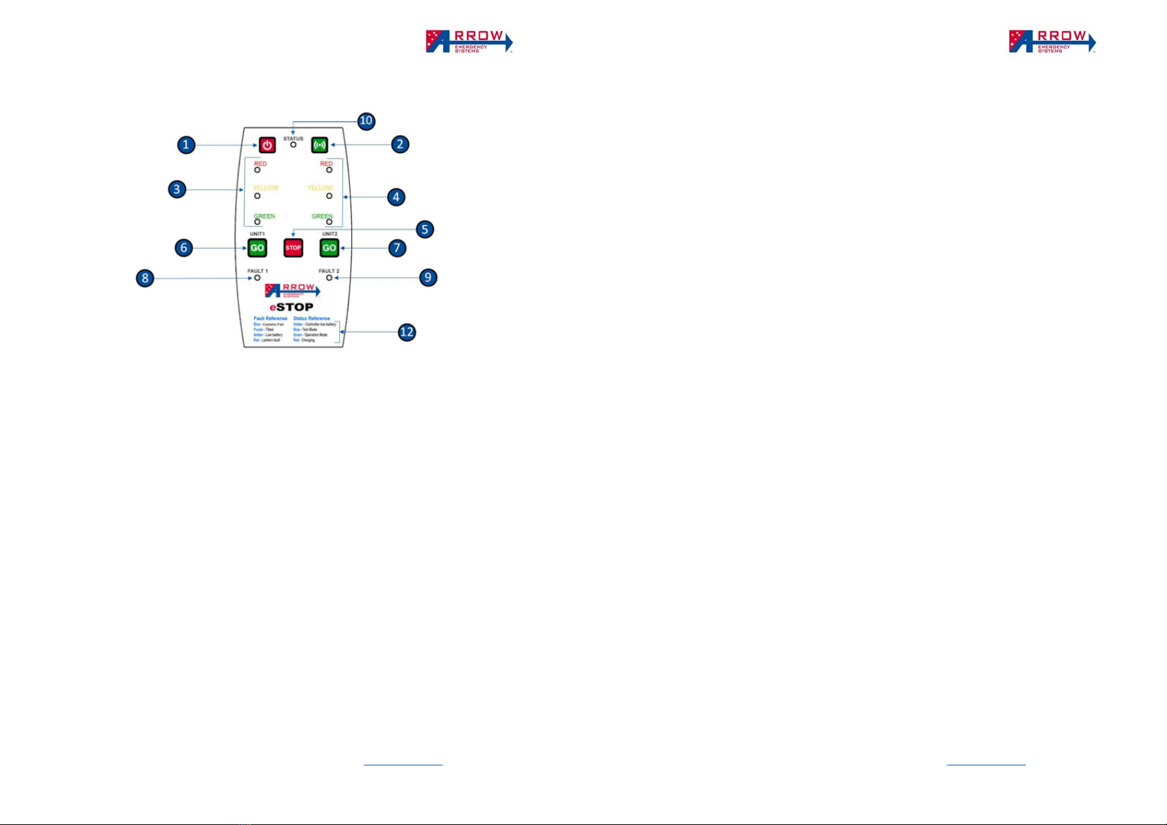
Hand Remote Controller – HRC
LED indicators – There is 3 type of LED indicators – Lantern, Status, Fault.
Lantern indicators ❸❹ reflects the signal status of the paired lantern units.
Status indicator ❿ represents the states and faults of the over system and indicates the following
colours:
o Red – when the HRC is off, Red indicates the HRC is charging. When the HRC is on, Red indicates
invalid press or fail pairing.
o Blue – once the HRC is powered on, the status indicator is Blue, which represents Test Mode.
o Green – when the HRC is off, Green indicates the HRC is fully charged and stopped charging. When
the HRC is on, Green indicates valid press or the system is in Operational Mode.
o Yellow/Amber – the Status will flash Yellow/Amber when the HRC batteries is low.
o Blank/no colour – the HRC is powered off, if Pressing the buttons does not sound a beep then the
HRC is faulty or battery is completely dead
Fault indicators ❽❾ represents the states and faults of the respected paired unit.
o Blue – HRC is paired to a lantern unit but communication fail (no connection, may need to re-pair).
o Purple – The paired lantern is tilted and/or rotated from its starting position after Activation.
o Green – The paired lantern is communicating and operating normal.
o Yellow/Amber – The paired lantern battery is low.
o Red – The Paired lantern has a lantern fault in one of the LED.
Modes of Operations – The system runs in 2 modes, Test Mode and Operation Mode
Test Mode (Status LED blue) - When the HRC first power up it is in Test Mode, during this mode you
can pair/un-pair any Lantern units (refer to pairing section). Once it’s paired to a Lantern units (and Fault
light is green), you can do a LED lantern test and check the battery of the Lantern unit (refer Lantern
Battery section).
Operation Mode (Status LED green) - Once the HRC is paired and the Fault LED is green, the system
is be activated into Operation Mode. During this Mode, the operations of a Typical Traffic Signal can be
controlled, where the lantern can be controlled to STOP (go to Red) or GO (go to Green).
eSTOP™ User Manual
Arrow Emergency Systems | 17 Bailey Court Brendale Q 4500 | P: (07) 3881 3302 | www.arrowes.com.au Page | 4
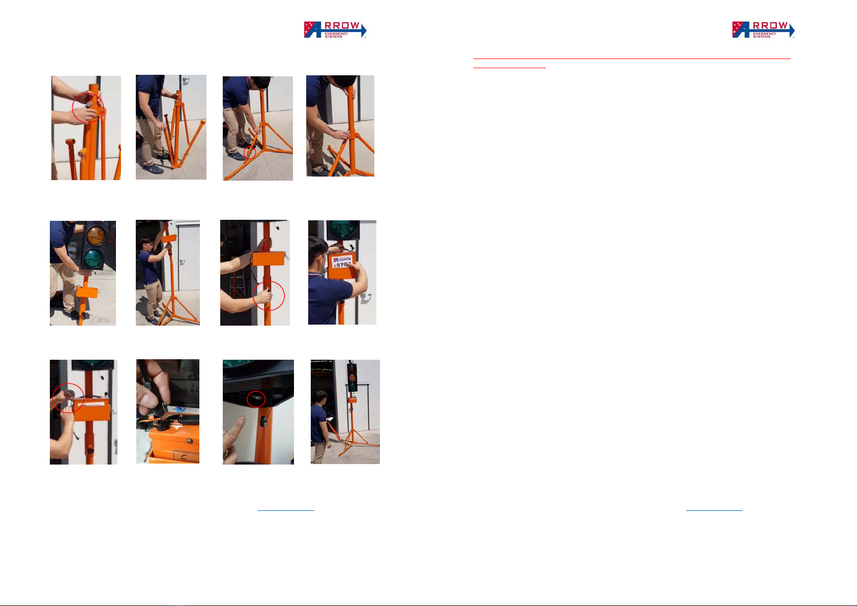
Operational Steps
1. Power On - Press and hold Power Button ❶ for 5 seconds to power on Handheld Remote
Control (HRC).
2. Fault indicators - When power is on Fault Indicator ❽❾ will show different colours
according to the fault hierarchy listed under Fault Reference ⓬ when more than one fault
occurs, the fault with lower hierarchy will not be displayed until higher level fault(s) have
been cleared.
3. Test - When first powered on, the HRC will starts in Test Mode and the Status Indicator
❿will show blue. During Test Mode the HRC can be used to pair to a specific eSTOP™ unit
(Refer to Pairing section). If the HRC is paired to an eSTOP™ unit the Fault Indicator ❽❾
will show Blue and change to green when Synced to the paired eSTOP™ unit (allow up to 1
minute for the Fault light to turn green and get synced). Once synced the HRC can be used
to control the eSTOP™ unit. Pressing Buttons ❻ or ❼ allows eSTOP™ lanterns to be
tested (A quick flashing sequence of the 3 colours to ensure the lights are working).
4. Activation - When ready to operate the eSTOP™, hold down Activation Button ❷ for 5
seconds to activate the synced eSTOP™ units into Operation Mode, the Status Indicator
❿ will then show Green. The eSTOP™ will only operate when Fault Indicator is green.
5. Start-up - Upon switching from Test Mode to Operation Mode the eSTOP™ lantern will
flash yellow for 5 seconds, then default to red. The Hand Control will lock for 5 seconds
and all buttons will not work during this time. After 5 seconds the eSTOP™ unit is in
Operation Mode.
6. Control Traffic Signals - Use Buttons ❺❻ or ❼ to operate the eSTOP™ for traffic
control. Use button ❻❼ to switch one or the other signal to turn green. (Note: in order
to turn a signal green one or both signal must be red first). Use button ❺ to change all
signals to red. (Note: the yellow lantern will activate for 4 seconds during the transition
from green to red. The LED indicators reflect the eSTOP™ lantern status).
7. De-activation - In Operation Mode, holding Activation Button❷ for 5 seconds returns the
eSTOP™ units to Test Mode. During transition from Operation Mode to Test Mode both
eSTOP™ unit lanterns flash yellow for 5 seconds.
8. Power off - In all modes, hold Power Button ❶ for 5 seconds to commence power off.
During Operation Mode the HRC will not power off if the paired units lost sync (comms
fail) to an eSTOP™ unit.
9. Switch off eSTOP™ power and disconnect battery cable before packing up.
Note: While in “off” mode, pressing “STOP” on the HRC will indicate battery life remaining.
In the event of forced power off is required on the HRC, pressing button “1” and “2” at the
same time forces the HRC to soft reset then powers off.