Control horn and servo arm settings
More control throw
Less control throw
Horns
Arms
ElevatorRudderAilerons
1. The table shows the factory settings for the
control horns and servo arms. Fly the aircraft at the
factory settings before making changes.
2. After flying, you may choose to adjust the linkage
positions for the desired control response.
08
Always turn your transmitter on first. Install a fully charged battery in the battery bay, then connect it to the ESC. In this
process, make sure that the throttle cut functionality is on, and that the throttle stick is secured in its lowest position- other-
wise, the propeller/fan will engage and possibly cause bodily harm.
Note: Please refer to your transmitter manual that came with your radio control system to perform a ground
range check. If the controls are not working correctly or if anything seems wrong, do not fly the model until you
correct the problem. Make certain all the servo wires are securely connected to the receiver and the transmitter
batteries have a good connection.
Find a flying site clear of buildings, trees, power lines and other obstructions. Until you know how much area will be
required and have mastered flying your plane in confined spaces, choose a site which is at least the size of two to three
football fields - a flying field specifically for R/C planes is best. Never fly near people - especially children, who can
wander unpredictably.
A radio range check should be performed prior to the first flight of the day. This test may assist you in detecting electronic
problems that may lead to a loss of control- problems such as low transmitter batteries, defective or damaged radio com-
ponents or radio interference. This usually requires an assistant and should be done at the flying site.
Before flying the model
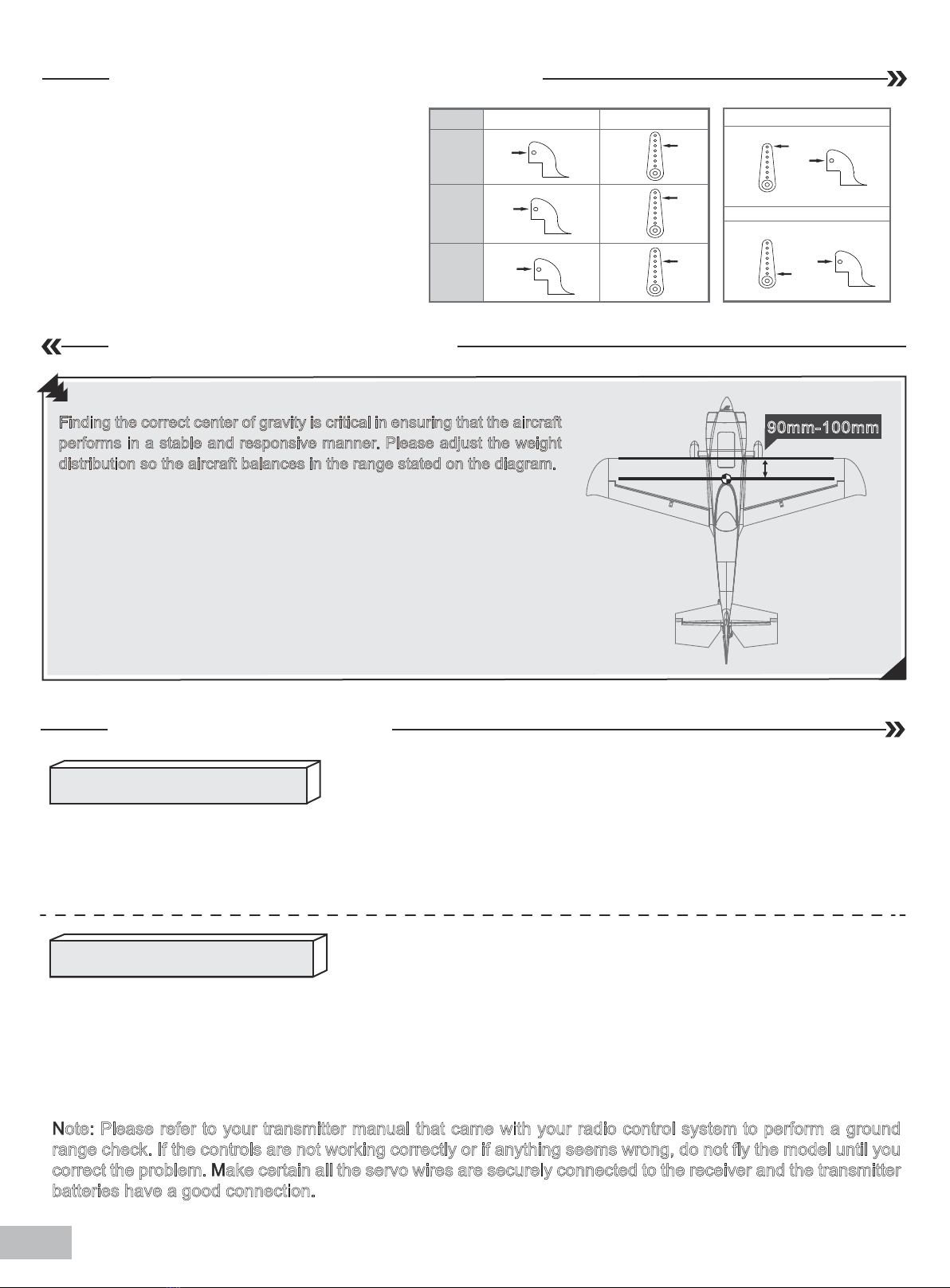
Finding the center of gravity
Find a suitable flying site
Performing a range check
Finding the correct center of gravity is critical in ensuring that the aircraft
performs in a stable and responsive manner. Please adjust the weight
distribution so the aircraft balances in the range stated on the diagram.
• Depending on the capacity and weight of your choosen flight
batteries, move the battery forward or backward to adjust the
center of gravity.
• If you cannot obtain the recommended CG by moving the battery to a
suitable location, you can also install a counterweight to achieve correct
CG. However, with the recommended battery size, a counterweight is not
required. We recommend flying without unnecessary counterweight.
90mm-100mm