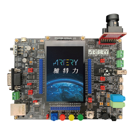
ARTERY AT-SURF-F437 User manual

AT-SURF-F437 User Manual
2022.3.24 1Rev 1.10
Evaluation board with AT32F437ZMT7 MCU
Introduction
AT-SURF-F437 evaluation board with a complete set of features helps the user to explore the high
performance of the 32-bit ARM®Cortex®-M4 microcontroller AT32F437 with FPU and expedite his
application development.
AT-SURF-F437 evaluation board is based on AT32F437ZMT7 microcontroller and includes large-
capacity SDRAM, QSPI Flash and RAM, and rich peripherals (three-color LEDs, buttons, two USB
micro-B, type A connector, Ethernet RJ45 connector, digital camera moduel, microphone and audio
input and outputs, microSD card interface) and communication interfaces such as RS-232, RS-485,
two CAN transceivers, 3.5 inch TFT-LCD touch screen. All this is aimed at enabling users to
experience all the features of the AT32F437 device.
The evaluation board comes with an embedded AT-Link-EZ for debugging/programming without
the need of other development tools.
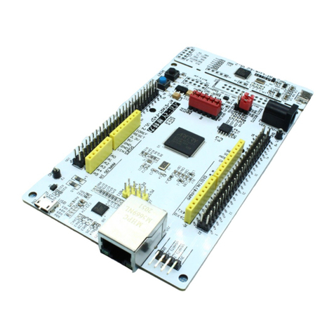
Figure 1. AT-SURF-F437 evaluation board

AT-SURF-F437 User Manual
2022.3.24 2Rev 1.10
Contents
1Overview................................................................................................................. 6
1.1 Features ...................................................................................................................6
1.2 Conventional terms .................................................................................................. 7
2Quick start .............................................................................................................. 8
2.1 Get started................................................................................................................8
3Hardware layout ..................................................................................................... 9
3.1 Power supply...........................................................................................................11
3.2 Embedded AT-Link-EZ for programming and debugging .........................................11
3.3 Boot mode selection................................................................................................11
3.4 External clock sources.............................................................................................11
3.5 LEDs ......................................................................................................................12
3.6 Buttons ...................................................................................................................12
3.7 Memories ...............................................................................................................12
3.7.1 SDRAM.......................................................................................................................12
3.7.2 SPI Flash memory......................................................................................................12
3.7.3 SPI PSRAM................................................................................................................12
3.7.4 I2C EEPROM..............................................................................................................12
3.8 RS-485 communication .......................................................................................... 12
3.9 RS-232 communication .......................................................................................... 13
3.10 CAN communication...............................................................................................13
3.11 microSD card..........................................................................................................13
3.12 Audio ......................................................................................................................13
3.13 Video ......................................................................................................................13
3.13.1 TFT-LCD connector....................................................................................................13
3.13.2 Digital camera module connector ..............................................................................13
3.14 OTGFS connector ..................................................................................................14
3.15 Ethernet connector .................................................................................................14
3.16 Other input and output devices...............................................................................14
3.16.1 Variable resistor..........................................................................................................14
3.16.2 Buzzer ........................................................................................................................14

AT-SURF-F437 User Manual
2022.3.24 3Rev 1.10
3.16.3 InfraRed receiver........................................................................................................15
3.17 Extension connector...............................................................................................15
3.18 0 Ω resistors ........................................................................................................... 15
4Pin assignment .................................................................................................... 16
5Schematics ........................................................................................................... 22
6Revision history ................................................................................................... 31

AT-SURF-F437 User Manual
2022.3.24 4Rev 1.10
List of tables
Table 1. Boot mode related jumpers.................................................................................................. 11
Table 2. 0 Ω resistor settings .............................................................................................................15
Table 3. AT32F437ZMT7 pin assignment..........................................................................................16
Table 4. Document revision history....................................................................................................31

AT-SURF-F437 User Manual
2022.3.24 5Rev 1.10
List of figures
Figure 1. AT-SURF-F437 evaluation board.........................................................................................1
Figure 2. Hardware block diagram ......................................................................................................9
Figure 3. Top layout ...........................................................................................................................10
Figure 4. Bottom layout......................................................................................................................10
Figure 5. Schematic for AT-Link-EZ and power ................................................................................22
Figure 6. Schematic for AT32F437ZMT7 MCU.................................................................................23
Figure 7. Schematic for SDRAM and TFT-LCD connector...............................................................24
Figure 8. Schematic for QSPI, microSD card slot and camera module connector...........................25
Figure 9. Schematic for Ethernet PHY and RJ45 connector.............................................................26
Figure 10. Schematic for audio..........................................................................................................27
Figure 11. Schematic for OTGFS, CAN, RS-485 and RS-232 connector.........................................28
Figure 12. Schematic for other devices.............................................................................................29
Figure 13. Schematic for extension connectors ................................................................................30

AT-SURF-F437 User Manual
2022.3.24 6Rev 1.10
1 Overview
1.1 Features
AT-SURF-F437 has the following features:
On-board 32-bit ARM®Cortex®-M4 core-based AT32F437ZMT7 microcontroller with 4032 KB
of Flash memory and 384 KB of SRAM, in LQFP144 package
On-board AT-Link-EZ for programming and debugging, without the need of an emulator
Power supply options:
−AT-LIink-EZ USB bus
−AT-SURF-F437 OTG1 or OTG2 bus (VBUS1 or VBUS2)
−VBAT can be supplied through a coin cell battery
Extension memories:
−32 MB of SDRAM (connected to XMC interface)
−16 MB of SPI Flash (connected to QSPI1 interface)
−8 MB SPI PSRAM (connected to QSPI2 interface)
Clock sources:
−8 MHz HEXT crystal
−32.768 kHz LEXT crystal
LEDs:
−LED1 (Red) indicates 3.3 V power-on
−User LED2 (three color) indicates the status of the application execution
−AT-Link-EZ has four LEDs (LD1~4) indicating its working status, refer to AT-Link user
manual for details
User interface
−2 user buttons, five-direction joystick and 1 reset button
−1 variable resistor connected to ADC
−Buzzer and IrDA receiver
Communication interfaces
−SPI4 is connected to extension connectors
−USART3 is connected to RS-485 transceiver
−UART5 is connected to RS-232 transceiver (D-Sub 9-pin male connector is available)
−TFT-LCD display control using I2C1
−I2C2 controls camera module, audio codec WM8988, EEPROM K24C02 and I/O extension
device PCA9555 and is connected to extension connector
−2 CAN transceivers
−microSD card connector
−OTGFS1 with USB type A and micro-B connectors
−OTGFS2 with a micro-B connector (To run in host mode, an OTG cable is required to
connect with external devices)
−Ethernet EMAC is connected to Ethernet PHY with RJ45 connector

AT-SURF-F437 User Manual
2022.3.24 7Rev 1.10
Audio
−Full-duplex I2S2 is connected to audio codec WM8988
−Audio power amplifier-driven speaker (on the back of the board) and 3.5 mm LINE_OUT
−Microphone and 3.5 mm LINE_IN
Video
−Digital camera module is connected to DVP interface
−3.5 inch 320 x 480 TFT-LCD parallel interface display (connected to XMC interface) with
capacitive touch panel
Note: Devices or modules attached to the board may be replaced with other compatible parts at the time
of shipment and PCB revision code remains unchanged without notice.
1.2 Conventional terms
Jumper JPx ON
Jumper fitted
Jumper JPx OFF
Jumped not fitted
Resistor Rx ON
Resistor soldered or connected with a 0 Ω resistor
Resistor Rx OFF
Resistor not soldered

AT-SURF-F437 User Manual
2022.3.24 8Rev 1.10
2 Quick start
2.1 Get started
Configure the AT-SURF-F437 evaluation board in the following order:
1. Insert camera module into the digital camera module connector CN3 with lens facing forward
2. Check the Jumper positions on the board
JP2 is connected to GND or OFF (BOOT0=0. BOOT0 has a pull-down resistor in the
AT32F437ZMT7)
JP3 is connected to GND (BOOT1=0)
3. Connect AT-Link-EZ to PC via a USB cable (Type A to micro-B), power the board via a USB
connector CN1, and turn on power switch SW1
4. TFT-LCD display shows the word ARTERY
5. LED1 (red) ON. LED2 blinks in white and then in green, red and blue

AT-SURF-F437 User Manual
2022.3.24 9Rev 1.10
3 Hardware layout
The AT-SURF-F437 evaluation board is designed around the AT32F437ZMT7 microcontroller in a
144-pin LQFP package.
Figure 2 illustrates the connections between the AT32F437ZMT7 and peripherals. Figure 3 and
Figure 4 Show the locations of these features on the AT-SURF-F437 evaluation board.
Figure 2. Hardware block diagram
SWD / SWO /
USART1
AT32F437ZMT7
XMC
I2C1
AT-Link-EZ
Micro-USB
Ethernet
PHY Ethernet
RJ45
USB type-A
Micro-USB
SDRAM
TFT-LCD
QSPI1SPI Flash
QSPI2SPI PSRAM
GPIO
Three color
LED
GPIOUser button
NRST
Reset
button
I2C2
EEPROM
I/O extension
IC
Five-direction
joystick
Buzzer
ADC1
Variable
resistor
USART3
SPI4
Extension
connector
RS-485
transceiver
RS-485
connector
Micro SD
card
connector
SDIO1
CAN1 CAN
transceiver CAN1
interface
CAN2 CAN
transceiver CAN2
interface
OTGFS1
OTGFS2 Micro-USB
EMAC
UART5
RS-232
transceiver
RS-232
connector
I2S2 Audio codec
Power
amplifier Speaker
Microphone
LINE_IN
LINE_OUT
I2C2
Camera
connector
DVP
Camera
module

AT-SURF-F437 User Manual
2022.3.24 10 Rev 1.10
Figure 3. Top layout
AT32F437ZMT7 Extension
connector
USB micro-B
connector
Power LED
AT-Link-EZ
Boot
mode
jumper
LINE_IN
interface
CR1220 coin
battery cell microSD card slot SPI4 Camera module
connector
I2C2
CAN2
interface
CAN1
interface
I2C EEPROM
Digital
microphone
LINE_OUT
interface
Audio
amplifier
IrDA
receiver
Audio codec
Active buzzer
I/O extension IC
Five-direction
joystick
User
buttons
Reset
button
Variable resistor
with rotary switch
TFT-LCD
Ethernet PHY
Three color
LED SDRAM
Ethernet RJ45
connector
RS-485
connector
SPI
Flash
SPI PSRAM
RS-232
connector
Power
switch
Extension
connector
USB Type-A connector
Figure 4. Bottom layout
Speaker

AT-SURF-F437 User Manual
2022.3.24 11 Rev 1.10
3.1 Power supply
The AT-SURF-F437 evaluation board is designed to be powered by a 5 V power supply via a USB
cable. It is also possible to configure the evaluation board to use the following three sources for 5 V
power supply:
USB connector (CN1, power switch SW1 ON) on the AT-Link-EZ;
USB connector (CN9 or CN10) on OTGFS1 or OTGFS2.
Then the 5 V power supply outputs 3.3 V for the microcontroller and peripherals via on-board DC-
DC switching power supply IC (U2).
LED1 (red) remains ON when the AT-SURF-F437 evaluation board is powered.
Note: PC has to be connected to the USB connector (CN1) on the AT-Link-EZ. Any other method cannot
power the AT-Link-EZ.
The VBAT pin on the AT32F437ZMT7 can be powered by on-board 3.3 V power supply (default
setting) via a JP4, or by a coin-battery cell CR1220.
3.2 Embedded AT-Link-EZ for programming and debugging
The evaluation board integrates ARTERY’s AT-Link-EZ for users to program/debug the
AT32F437ZMT7 on the AT-SURF-F437. AT-Link-EZ supports SWD interface mode and SWO
debugging. And a virtual COM port (VCP) is connected to the USART1_TX/USART1_RX
(PA9/PA10) of the AT32F437ZMT7 via a JP1 (default ON).
Please refer to AT-Link User Manual for complete details on AT-Link-EZ, including LEDs (LD1~4),
firmware upgrade and points for attention.
3.3 Boot mode selection
At startup, three different boot modes are available for selection through pin configuration.
Table 1. Boot mode related jumpers
Jumper
Pin configuration
Boot from
BOOT1
BOOT0
JP2 is connected to GDN or OFF;
JP3 OFF or optional
X
0
Boot from internal Flash memory (default setting)
JP2 is connected to VDD
JP3 is connected to GND
0
1
Boot from boot memory with boot loader for ISP
JP2 is connected to VDD
JP3 is connected to VDD
1
1
Boot from internal SRAM for debugging
3.4 External clock sources
For the AT32F437ZMT7 MCU, its external clock sources include:
High-speed external crystal (HEXT): provided by 8 MHz crystal (X2) on the board.
Low-speed external crystal (LEXT): provided by 32.768 kHz crystal (Y1) on the board.
25 MHz crystal (X3) for Ethernet PHY: it can be selected as a clock source via JP8 (default
setting).
CLKOUT1 output (PA8) from the AT32F437ZMT7.

AT-SURF-F437 User Manual
2022.3.24 12 Rev 1.10
3.5 LEDs
Power LED1
Red LED: indicates that the AT-SATRT-F437 evaluation board is being powered by 3.3 V.
User LED2(RGB_LED)
The Three-color LED, red, green and blue, is connected to PB10, PD13 and PB5 of the
AT32F437ZMT7 respectively that adjust color change and brightness by controlling PWM duty
cycle of each color.
3.6 Buttons
Reset B0: reset button
It is connected to the NRST to reset the AT32F437ZMT7.
User B1 and user B2: User button (Key1 and Key2)
The B1 is connected to PA0 of the AT32F437ZMT7 as a wakeup button.
The B2 is connected to PC13 of the AT32F437ZMT7 as a TAMPER-RTC button.
User B3: 5-direction joystick
The 5-direction joystick B3 is connected to I/O extension chip (U21) and can be accessed via
the I2C2 (PH2 and PH3) of the AT32F437ZMT7.
3.7 Memories
3.7.1 SDRAM
1 x 16-bit 32 Mbytes of SDRAM W9825G6KH-6 (U6) is available on the board. The SDRAM is
connected to the AT32F437ZMT7 via the XMC interface and acts as program/data/random access
memory expansion.
3.7.2 SPI Flash memory
1 x 16 Mbytes of SPI Flash memory W25Q128JVSQ (U7) is available on the board. The SPI Flash
is connected to the AT32F437ZMT7 via a QSPI1 interface and acts as program/data memory
expansion.
3.7.3 SPI PSRAM
1 x 8 MByste of SPI PSRAM LY68L6400S (U8) is available on the board. The SPI PSRAM is
connected to the AT32F437ZMT7 via a QSPI2 interface and acts as random access memory
expansion.
3.7.4 I2C EEPROM
1 x I2C EEPROM K24C02 (U20) is available on the board. It is connected to the AT32F437ZMT7
via an I2C2 interface as an extended data memory. The I2C address of EEPROM is 0b1010000.
3.8 RS-485 communication
The RS-485 communication transceiver (U16) is connected to USART3 via the JP11 (default ON).
It has a bolted connector CN11 to connect with external devices. A 120 Ωterminal resistor R71 is
mounted on the board by default. The resistor can be removed if it is unused.

AT-SURF-F437 User Manual
2022.3.24 13 Rev 1.10
3.9 RS-232 communication
The RS-232 communication transceiver (U18) is connected to UART5 via the JP12 (default ON). It
has a 9-pin D-Sub male connector (CN12) to connect with external devices. Only TX and RX
signals are supported by the communication interface.
3.10 CAN communication
The AT-SURF-F437 evaluation board supports CAN1 and CAN2 interfaces. The 5 V VCC is
provided via the transceiver IC TJA1042T/3 (U12 and U13). The bolted connectors (CN6 and CN7)
are available for external communication. The 120 Ω terminal resistors R63 and R64 are mounted
on the CAN1 and CAN2 by default. These resistors can be removed if they are unused.
Note: To use CAN1, the JP7 jumper cap has to be moved from QSPI2 (default setting) to CAN1.
Note: To use CAN2, the JP10 jumper cap has to be moved from I2S2 (default setting) to CAN2.
3.11 microSD card
A microSD card can be inserted into CN4 to connect with SDIO1-related pins. The Cd (card detect)
is connected to IO0_3 of the I/O extension connector U21 for the purpose of detection.
3.12 Audio
The AT32F437ZMT7 supports two full-duplex I2S modules. The AT-SURF-F437 evaluation board is
connected to the audio codec WM8988 (U11) via the I2S2 to support a loudspeaker or LINE_OUT
playback, and microphone or LINE_IN recording. The AT32F437ZMT7 communicates with the
audio codec via the I2C2. The I2C address of WM8988 is 0b0011010.
A 3.5 mm stereo LINE_OUT interface (CN14, light green) mounted on the AT-SURF-F437 board is
linked to the output1 on the WM8988 and able to connect with a stereo playback device. A small
speaker (connect to CN5 on the back of the board) is also available on the board, and it is driven
by an audio power amplifier TC8002D (U17). The audio source of such speaker is provided by the
left channel on the output2 on the WM8988, or by PWM passing a low pass filter on the PA15 of
the AT32F437ZMT7 when JP15 ON (default OFF).
A digital microphone (U14) on the evaluation board is connected to the left and right channels of
the input1 on the WM8988. A 3.5 mm stereo LINE_IN input interface (CN13, light blue) on the
board is linked to the input2 on the WM8988 and able to connect with an external device for stereo
input.
3.13 Video
3.13.1 TFT-LCD connector
A 3.5 inch 320 x 480 TFT-LCD with capacitive touch display is connected to CN2 by default. The
AT32F437ZMT7 uses the 16-bit XMC parallel interface to transfer video data. The backlight is
turned on through a pull-up resistor R13 by default when the IO0_0 pin of I/O extension connector
U21 is not enabled. The display touch signal communicates with the AT32F437ZMT7 via the I2C1
(PB6 and PB7).
3.13.2 Digital camera module connector
The camera module is connected to DVP of the AT32F437ZMT7 via a digital camera module
connector (CN3). The data width is 8 bit. The AT32F437ZMT7 uses I2C2 as a camera module
control interface to initialize and access the camera module.

AT-SURF-F437 User Manual
2022.3.24 14 Rev 1.10
3.14 OTGFS connector
The AT-SURF-F437 evaluation board supports OTGFS1 and OTGFS2 full-speed/low-speed host
or full-speed device communication mode via a USB micro-B connector (CN9 and CN10). As a
device, the AT32F437ZMT7 is directly connected to host via a USB micro-B cable, and either VBUS1
or VBUS2 can be used to supply 5 V for the AT-SURF-F437 evaluation board. As a host, the
AT32F437ZMT7 is connected to an external device through a USB OTG cable, and the OTGFS1
and OTGFS2 provide power to the device via the USB micro-B connector by controlling SI2301
switch through IO1_5 and IO1_6 of the I/O extension connector (U21) respectively.
Additionally, a USB type A connector (CN8) is available on the AT-SURF-F437 evaluation board. It
acts as an OTGFS1 host interface for connecting to devices such as USB thumb drive, without the
need of a USB OTG cable. The USB type A connector is without power switch control.
Note: To use OTGFS1_VBUS or OTGFS1_ID feature, the JP1 jumper has to be OFF (default ON). In this
case, either PA9 or PA10 is disconnected with AT-Link-EZ to avoid impacting OTGFS1.
Note: To OTGFS2 feature, the JP14 jumper cap has to be moved from I2S2 (default setting) to the OTG2.
3.15 Ethernet connector
The AT-SURF-F437 evaluation board supports 10/100 Mbps dual speed Ethernet communication
by an Ethernet PHY DM9162 (U9) and RJ45 connector (CN15 with isolation transformer and
LEDs).
Ethernet PHY is connected to EMAC of the AT32F437ZMT7 via the RMII interface. Either a 25
MHz crystal (X3) (default setting) or CLKOUT1 (PA8) of the AT32F437ZMT7 is selected through
JP8 to clock the XT1 of PHY so as to provide 25 MHz clock for PHY. A 50 MHz clock for
RMII_REF_CLK (PA1) of the AT32F437ZMT7 is provided by a 50MCLK pin of PHY.
At power-on, the address [3:0] of PHY is 0x3 by default. After power-on, software is able to re-
specify the PHY address via the SMI interface of PHY.
The default operating mode for PHY is in power-down mode after power-on. Thus it is important to
set the PWRDWN pin of DM9162 to low level via an I/O extension connector (U21) in order to
ensure PHY to work normally.
3.16 Other input and output devices
3.16.1 Variable resistor
A variable resistor (VR) with a rotary switch is connected to ADC12_IN5 (PA5) via JP6 (default
ON). It is reflected in ADC conversion value by changing its voltage divider via a rotary switch. It is
also possible for the user to inject a to-be-measured voltage signal through the first pin of VR when
JPP OFF, but not exceed 3.6 V.
When JP6 OFF, the first pin of VR can act as DAC2_OUT of the AT32F437ZMT7.
By default, VREF+ is connected to 3.3 V power supply. To customize VREF+ (reference voltage), R10
has to be OFF (default ON). The reference voltage is input from T1 point.
3.16.2 Buzzer
An active buzzer (BUZZ) is switched on or off by a triode SS8050 (Q1) that is controlled by the
IO0_4 pin of the I/O extension connector (U21)

AT-SURF-F437 User Manual
2022.3.24 15 Rev 1.10
3.16.3 InfraRed receiver
InfraRed Receiver module IRM-56384 (U22) is used to receive and demodulate InfraRed remote
control signals and output them to PC8 of the AT32F437ZMT7. The InfraRed remote control
command can be decoded by multiplexed timer capture feature.
3.17 Extension connector
The P4 and P5 of extension connector are connected to GPIOs of the AT-SURF-F437
microcontroller and can be measured through oscilloscope, logic analyzer or voltmeter. As the P6
of extension connector corresponds to CN2, it is also possible to measure and debug LCD pins via
P6 when LCD is connected to CN2.
In addition, I2C2 and SPI4 pins are linked to the P7 and P8 of extension connector, making it
possible to connect with other external functional modules.
Four GND hooks (TP1, TP2, TP3 and TP4) around four corners of the board makes it convenient
for instruments to be grounded while measuring.
3.18 0 Ω resistors
Table 2. 0 Ωresistor settings
Resistor
Status(1)
Description
R10
(VREF+ power supply)
ON
VREF+ is connected to 3.3 V
OFF
VREF+ is provided through T1
R55
(backlight power supply
for TFT-LCD )
ON
The backlight of TFT-LCD is powered by 5 V.
OFF
The backlight of TFT-LCD is not powered.
R59, R61
(speaker audio source)
ON, OFF
Audio source is provided by the left channel of the audio codec
output 2
OFF, ON
Audio source is provided by the right channel of the audio codec
output 2
R114
(OTG1 VBUS)
OFF
When used as GPIO or USART1_TX, PA9 is disconnected from
OTG1 VBUS1 to avoid exception
ON
When used as OTGFS1_VBUS, PA9 is connected to OTG1 VBUS1.
In such case, it is recommended to keep jumper cap OFF on JP1
PA9 side
R113
(OTG2 VBUS)
OFF
When used as GPIO, I2S2_CK or CAN2_TX, PB13 is disconnected
with OTG2 VBUS2 to avoid exception
ON
When used as OTGFS2_VBUS, PB13 is connected with OTG2
VBUS2. In such case, it is recommended to keep jumper cap OFF
on JP10 PB13 side
R118, R119
(CAN1 transceiver power
supply)
OFF, ON
CAN1 transceiver is powered by 5 V
ON, OFF
CAN1 transceiver is powered by 3.3 V
R115, R116
(CAN2 transceiver power
supply)
OFF, ON
CAN2 transceiver is powered by 5 V
ON, OFF
CAN2 transceiver is powered by 3.3 V
(1) Rx default settings are expressed in bold.

AT-SURF-F437 User Manual
2022.3.24 16 Rev 1.10
4 Pin assignment
To offer a complete picture of the full-featured AT32F437 microcontroller, each of GPIOs on the
microcontroller is presented with specific features and connected to one or more devices externally.
If there is concern about the simultaneous operation of several devices controlled by the same pin,
JPx or 0 Ω resistor is available on the evaluation board for users to configure device connection.
Most of the GPIOs are connected to extension connectors, P4, P5 and P6, to support
measurement, debugging or expansion function. Table 3 presents I/O assignment of
AT32F437ZMT7.
Table 3. AT32F437ZMT7 pin assignment
Pin
Pin name
Function
Connection
device1
Connection
device2
Connection
device3
Connection
device4
Jumper or
0 Ω resistor
Extension
connector
1
PE2
SPI4_SCK
-
-
P8[5]
-
-
P4[4]
2
PE3
PE3
-
TFT-LCD interface
(CN2)
-
-
-
P6[31]
3
PE4
SPI4_CS
-
-
P8[4]
-
-
P4[5]
4
PE5
DVP_D6 /
SPI4_MISO
-
Camera interface
(CN3)
P8[7]
-
-
P4[6]
5
PE6
DVP_D6 /
SPI4_MOSI
-
Camera interface
(CN3)
P8[6]
-
-
P4[7]
7
PC13
PC13 /
TAMPER_RTC
Key2 (B2)
-
-
-
-
P4[8]
8
PC14
LEXT_IN
32 kHz crystal (Y1)
-
-
-
-
-
9
PC15
LEXT_OUT
32 kHz crystal (Y1)
-
-
-
-
-
10
PF0
XMC_A0
W9825G6KH (U6)
-
-
-
-
P6[2]
11
PF1
XMC_A1
W9825G6KH (U6)
-
-
-
-
P4[9]
12
PF2
XMC_A2
W9825G6KH (U6)
-
-
-
-
P4[10]
13
PF3
XMC_A3
W9825G6KH (U6)
-
-
-
-
P4[11]
14
PF4
XMC_A4
W9825G6KH (U6)
-
-
-
-
P4[12]
15
PF5
XMC_A5
W9825G6KH (U6)
-
-
-
-
P4[13]
18
PF6
QSPI1_IO3
W25Q128JV (U7)
-
-
-
-
P4[14]
19
PF7
QSPI1_IO2
W25Q128JV (U7)
-
-
-
-
P4[15]
20
PF8
QSPI1_IO0
W25Q128JV (U7)
-
-
-
-
P4[16]
21
PF9
QSPI1_IO1
W25Q128JV (U7)
-
-
-
-
P4[17]
22
PF10
QSPI1_SCK
W25Q128JV (U7)
-
-
-
-
P4[18]
23
PH0
HEXT_IN
8 MHz crystal (X2)
-
-
-
-
-

AT-SURF-F437 User Manual
2022.3.24 17 Rev 1.10
Pin
Pin name
Function
Connection
device1
Connection
device2
Connection
device3
Connection
device4
Jumper or
0 Ω resistor
Extension
connector
24
PH1
HEXT_OUT
8 MHz crystal (X2)
-
-
-
-
-
26
PC0
XMC_SDNWE
W9825G6KH (U6)
-
-
-
-
P4[19]
27
PC1
EMAC_MDC
DM9162 (U9)
-
-
-
-
P4[20]
28
PC2
XMC_SDCS0
W9825G6KH (U6)
-
-
-
-
P4[21]
29
PC3
XMC_SDCKE0
W9825G6KH (U6)
-
-
-
-
P4[22]
34
PA0
PA0 / WKUP
Key1 (B1)
-
-
-
-
P4[23]
35
PA1
EMAC_RMII_
REF_CLK
DM9162 (U9)
-
-
-
-
P4[24]
36
PA2
EMAC_MDIO
DM9162 (U9)
-
-
-
-
P4[25]
37
PA3
QSPI2_IO3
LY68L6400 (U8)
-
-
-
-
P4[26]
40
PA4
DVP_HSYNC
-
Camera interface
(CN3)
-
-
-
P4[27]
41
PA5
ADC12_IN5 /
DAC2_OUT
Variable resistor
(VR)
-
-
-
JP6[1, 2]
P4[28]
42
PA6
DVP_PCLK
-
Camera interface
(CN3)
-
-
-
P4[29]
43
PA7
EMAC_RMII_
CRS_DV
DM9162 (U9)
-
-
-
-
P4[30]
44
PC4
EMAC_RMII_
RXD0
DM9162 (U9)
-
-
-
-
P4[31]
45
PC5
EMAC_RMII_
RXD1
DM9162 (U9)
-
-
-
-
P4[32]
46
PB0
QSPI2_IO0
LY68L6400 (U8)
-
-
-
-
P4[33]
47
PB1
QSPI2_SCK
LY68L6400 (U8)
-
-
-
-
P4[34]
48
PB2 /
BOOT1
BOOT1
JP3[1, 2, 3]
-
-
-
-
P4[35]
49
PF11
XMC_SDNRAS
W9825G6KH (U6)
-
-
-
-
P4[36]
50
PF12
XMC_A6
W9825G6KH (U6)
-
-
-
-
P4[37]
53
PF13
XMC_A7
W9825G6KH (U6)
-
-
-
-
P4[38]
54
PF14
XMC_A8
W9825G6KH (U6)
-
-
-
-
P4[39]
55
PF15
XMC_A9
W9825G6KH (U6)
-
-
-
-
P4[40]
56
PG0
XMC_A10
W9825G6KH (U6)
TFT-LCD interface
(CN2)
-
-
-
P5[39]

AT-SURF-F437 User Manual
2022.3.24 18 Rev 1.10
Pin
Pin name
Function
Connection
device1
Connection
device2
Connection
device3
Connection
device4
Jumper or
0 Ω resistor
Extension
connector
57
PG1
XMC_A11
W9825G6KH (U6)
-
-
-
-
P5[38]
58
PE7
XMC_D4
W9825G6KH (U6)
TFT-LCD interface
(CN2)
-
-
-
P6[10]
59
PE8
XMC_D5
W9825G6KH (U6)
TFT-LCD interface
(CN2)
-
-
-
P6[11]
60
PE9
XMC_D6
W9825G6KH (U6)
TFT-LCD interface
(CN2)
-
-
-
P6[12]
63
PE10
XMC_D7
W9825G6KH (U6)
TFT-LCD interface
(CN2)
-
-
-
P6[13]
64
PE11
XMC_D8
W9825G6KH (U6)
TFT-LCD interface
(CN2)
-
-
-
P6[14]
65
PE12
XMC_D9
W9825G6KH (U6)
TFT-LCD interface
(CN2)
-
-
-
P6[15]
66
PE13
XMC_D10
W9825G6KH (U6)
TFT-LCD interface
(CN2)
-
-
-
P6[16]
67
PE14
XMC_D11
W9825G6KH (U6)
TFT-LCD interface
(CN2)
-
-
-
P6[17]
68
PE15
XMC_D12
W9825G6KH (U6)
TFT-LCD interface
(CN2)
-
-
-
P6[18]
69
PB10
TMR2_CH3
RGB_LED (LED2)
-
-
-
-
P5[37]
70
PB11
EMAC_RMII_
TX_EN
DM9162 (U9)
-
-
-
-
P5[36]
71
PH3
I2C2_SDA
WM8988 (U10)
Camera interface
(CN3)
PCA9555
(U21)
K24C02
(U20)
-
P5[35]
P7[3]
73
PB12
I2S2_WS /
CAN2_RX /
OTGFS2_ID
WM8988 (U10)
TJA1042T/3 (U13)
OTG2
interface
(CN10)
-
JP10[1, 3, 5]
P5[34]
74
PB13
I2S2_CK /
CAN2_TX /
OTGFS2_VBUS
WM8988 (U10)
TJA1042T/3 (U13)
OTG2
interface
(CN10)
-
JP10[2, 4, 6]
R113
P5[33]
75
PB14
I2S2_SDEXT /
OTGFS2_D-
WM8988 (U10)
-
OTG2
interface
(CN10)
-
JP14[1, 3, 5]
-
76
PB15
I2S2_SD /
OTGFS2_D+
WM8988 (U10)
-
OTG2
interface
(CN10)
-
JP14[2, 4, 6]
-

AT-SURF-F437 User Manual
2022.3.24 19 Rev 1.10
Pin
Pin name
Function
Connection
device1
Connection
device2
Connection
device3
Connection
device4
Jumper or
0 Ω resistor
Extension
connector
77
PD8
XMC_D13
W9825G6KH (U6)
TFT-LCD interface
(CN2)
-
-
-
P6[19]
78
PD9
XMC_D14
W9825G6KH (U6)
TFT-LCD interface
(CN2)
-
-
-
P6[20]
79
PD10
XMC_D15
W9825G6KH (U6)
TFT-LCD interface
(CN2)
-
-
-
P6[21]
80
PD11
PD11
-
TFT-LCD interface
(CN2)
-
-
-
P6[33]
81
PD12
USART3_
RTS_DE
-
SP3485EN (U16)
-
-
-
P5[32]
82
PD13
TMR4_CH2
RGB_LED (LED2)
-
-
-
-
P5[31]
85
PD14
XMC_D0
W9825G6KH (U6)
TFT-LCD interface
(CN2)
-
-
-
P6[6]
86
PD15
XMC_D1
W9825G6KH (U6)
TFT-LCD interface
(CN2)
-
-
-
P6[7]
87
PG2
XMC_A12
W9825G6KH (U6)
-
-
-
-
P5[30]
88
PG3
PG3
-
-
PCA9555
(U21)
-
-
P5[29]
89
PG4
XMC_SDBA0
W9825G6KH (U6)
-
-
-
-
P5[28]
90
PG5
XMC_SDBA1
W9825G6KH (U6)
-
-
-
-
P5[27]
91
PG6
QSPI1_CS
W25Q128JV(U7)
-
-
-
-
P5[26]
92
PG7
PG7
-
TFT-LCD interface
(CN2)
-
-
-
P6[29]
93
PG8
XMC_SDCLK
W9825G6KH (U6)
-
-
-
-
P5[25]
96
PC6
I2S2_MCK /
DVP_D0
WM8988 (U10)
Camera interface
(CN3)
-
-
-
P5[24]
97
PC7
DVP_D1
-
Camera interface
(CN3)
-
-
-
P5[23]
98
PC8
DVP_D2 /
TMR3/8/20_CH3
-
Camera interface
(CN3)
IRM-56384
(U22)
-
-
P5[22]
99
PC9
SDIO1_D1
microSD card slot
(CN4)
-
-
-
-
P5[21]
100
PA8
CLKOUT1
DM9162 (U9)
Camera interface
(CN3)
-
-
JP8[2, 3]
P5[20]

AT-SURF-F437 User Manual
2022.3.24 20 Rev 1.10
Pin
Pin name
Function
Connection
device1
Connection
device2
Connection
device3
Connection
device4
Jumper or
0 Ω resistor
Extension
connector
101
PA9
USART1_TX /
OTGFS1_VBUS
AT-Link-EZ
(VCOM_RX)
OTG1 interface
(CN9)
-
-
JP1[3, 4]
R114
102
PA10
USART1_RX /
OTGFS1_ID
AT-Link-EZ
(VCOM_TX)
OTG1 interface
(CN9)
-
-
JP1[1, 2]
103
PA11
OTGFS1_D-
-
OTG1 interface
(CN9)
-
-
P5[19]
104
PA12
OTGFS1_D+
-
OTG1 interface
(CN9)
-
-
P5[18]
105
PA13
SWDIO
AT-Link-EZ
(SWDIO)
-
-
-
-
P5[17]
P3[1]
106
PH2
I2C2_SCL
WM8988 (U10)
Camera interface
(CN3)
PCA9555
(U21)
K24C02
(U20)
-
P5[16]
P7[4]
109
PA14
SWCLK
AT-Link-EZ
(SWCLK)
-
-
-
-
P5[15]
P3[2]
110
PA15
TMR2_CH1
TC8002D (U17)
-
-
-
JP15[1, 2]
P5[14]
111
PC10
SDIO1_D2 /
USART3_TX
microSD card slot
(CN4)
SP3485EN (U16)
-
-
JP11[1, 2]
-
112
PC11
SDIO1_D3 /
USART3_RX
microSD card slot
(CN4)
SP3485EN (U16)
-
-
JP11[3, 4]
-
113
PC12
SDIO1_CK /
UART5_TX
microSD card slot
(CN4)
SP3232EEY (U18)
-
-
JP12[1, 2]
114
PD0
XMC_D2
W9825G6KH (U6)
TFT-LCD interface
(CN2)
-
-
-
P6[8]
115
PD1
XMC_D3
W9825G6KH (U6)
TFT-LCD interface
(CN2)
-
-
-
P6[9]
116
PD2
SDIO1_CMD /
UART5_RX
microSD card slot
CN4)
SP3232EEY (U18)
-
-
JP12[3, 4]
P5[12]
117
PD3
DVP_D5
-
Camera interface
(CN3)
-
-
-
P5[11]
118
PD4
XMC_NOE
-
TFT-LCD interface
(CN2)
-
-
-
P6[4]
119
PD5
XMC_NWE
-
TFT-LCD interface
(CN2)
-
-
-
P6[3]
122
PD6
PD6
-
Camera interface
(CN3)
-
-
-
P5[10]
Table of contents
Other ARTERY Motherboard manuals

ARTERY
ARTERY AT-START-F403 User manual

ARTERY
ARTERY AT32F415 Series User manual

ARTERY
ARTERY AT32F435 Series Specification sheet

ARTERY
ARTERY AT-START-WB415 User manual

ARTERY
ARTERY AT-START-F407 User manual

ARTERY
ARTERY AT32-Video-EV User manual

ARTERY
ARTERY AT32-Comm-EV User manual

ARTERY
ARTERY AT-START-F425 User manual

ARTERY
ARTERY AT32F4 Series User manual
Popular Motherboard manuals by other brands

PC Partner
PC Partner 35-AA14-X0-XX Technical reference booklet

Measurement Computing
Measurement Computing BTH-1208LS-OEM user guide

MSI
MSI P55 GD80 - Motherboard - ATX user guide

PSI
PSI DRS4 user manual

Linear Technology
Linear Technology DC1418A-A quick start guide

IEI Technology
IEI Technology WAFER-LX2-800 Quick installation guide