ARTERY AT32F435 Series Specification sheet

AT32F435 & AT32F437 Get Started Guide
2022.4.20 1 Ver 2.0.0
AN0128
Application Note
AT32F435 & AT32F437 Get Started Guide
Introduction
This application note is used to help users quickly develop projects using AT32F435xx/AT32F437xx,
where AT32F437 is designed with EMAC function.
Note: The corresponding code in this application note is developed on the basis of V2.x.x BSP provided by
Artery. For other versions of BSP, please pay attention to the differences in usage.
Applicable products:
Product number
AT32F435xx
AT32F437xx

AT32F435 & AT32F437 Get Started Guide
2022.4.20 2 Ver 2.0.0
Contents
Preliminary environment preparation.................................................................. 5
Set up AT32 development environment.................................................................... 5
Debug tools and development board...........................................................................5
Programming tools and software.................................................................................5
AT32 Keil and IAR development environment.............................................................6
AT32F403A/407 replacement process.........................................................................9
AT32F435 /AT32F437 enhanced functional configuration ........................................ 9
PLL clock settings ........................................................................................................9
How to use FPU (floating point unit)..........................................................................10
AT32F435 /AT32F437 zero-wait/non-zero wait Flash and embedded SRAM
configurations.........................................................................................................................10
Encryption (access protection, erase/program protection)........................................15
RecognizeAT32 in program and other IC methods...................................................18
AT32F435/AT32F437 advanced functions.................................................................19
FAQ about download and compilation process ............................................... 21
Enter Hard Fault Handler when starting program ................................................... 21
Errors in program downloading............................................................................... 21
Error: Flash Download failed–“Cortex-M4” ................................................................21
No Debug Unit Device found......................................................................................22
RDDI-DAP Error.........................................................................................................22
ISP interface gets stuck during download..................................................................22
AT32 download resuming...........................................................................................22
Security Library (sLib)......................................................................................... 23
Introduction.............................................................................................................23
Principles of application..........................................................................................23
Security library application...................................................................................... 23
Revision history................................................................................................... 24

AT32F435 & AT32F437 Get Started Guide
2022.4.20 4 Ver 2.0.0
List of Figures
Figure 1. AT32F435 development board.............................................................................................5
Figure 2. Install ArteryTek.AT32F435_437_DFP.................................................................................6
Figure 3. Install Keil4_AT32MCU_AddOn...........................................................................................6
Figure 4. Pack Installer icon in Keil .....................................................................................................7
Figure 5. Keil Debug............................................................................................................................7
Figure 6. Keil Debug Settings..............................................................................................................7
Figure 7. Keil Utilities...........................................................................................................................7
Figure 8. Install IAR_AT32MCU_AddOn.............................................................................................8
Figure 9. IAR Debug............................................................................................................................8
Figure 10. IAR CMSIS-DAP.................................................................................................................8
Figure 11. PLL auto step-by-step system clock switch configuration..................................................9
Figure 12. ICP Programmer –User system data..............................................................................11
Figure 13. User system data - set SRAM size ..................................................................................12
Figure 14. ISP Programmer - Edit User system data........................................................................12
Figure 15. Define Extend_SRAM(void) to change SRAM size.........................................................13
Figure 16. Change SRAM size in Keil startup file .............................................................................14
Figure 17. Change SRAM size in IAR startup file .............................................................................14
Figure 18. ISP programmer –enable access protection...................................................................16
Figure 19. ISP programmer –disable access protection..................................................................16
Figure 20. ICP Programmer –enable erase/program protection......................................................17
Figure 21. ICP programmer –disable erase/program protection......................................................18
Figure 22. Read Cortex model...........................................................................................................18
Figure 23. Read PID and UID............................................................................................................19
Figure 24.AT-SURF-F437 development board.................................................................................20
Figure 25.Add code to enable FPU ..................................................................................................21
Figure 26. Error: Flash Download failed–“Cortex- 4” ........................................................................21

AT32F435 & AT32F437 Get Started Guide
2022.4.20 5 Ver 2.0.0
Preliminary environment preparation
Download the development environment from Artery’s official website:
http://www.arterytek.com
Set up AT32 development environment
Debug tools and development board
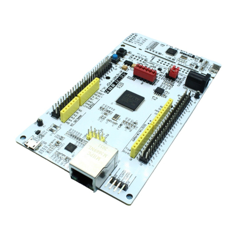
The AT32F435 /AT32F437 development boards are designed with AT-Link-EZ, as shown in the left
red box of the figure below. The debug tool AT-Link-EZ can also be disassembled from the
development board and used separately with other circuit boards. It supports IDE online debugging,
online programming, USB-to-serial interface, and other functions.
Figure 1. AT32F435 development board
Programming tools and software
AT programming tools and software: AT-Link /AT-Link-Pro /AT-Link-ISO /AT-Link-EZ /J-Link,
ICP/ISP.
Third-party programming tools:
Xuanwei: https://xuanweikeji.taobao.com
MaxWiz: www.maxwiz.com.cn
ZLG: http://tools.zlg.cn/tools
Amomcu: http://www.amomcu.cn
For details about ICP, refer to UM_ICP_Programmer. Download the ICP tool from Artery's
official website and extract files.
File path: Artery_ICP_Programmer_Vx.x.xx\Document\UM_ICP_Programmer.
For details about ISP, refer to UM_ISP_Programmer. Download the ISP tool from Artery's
official website and extract files.
File path: Artery_ISP_Programmer_Vx.x.xx\Document\UM_ISP_Programmer.
For details aboutAT-Link, refer to UM0004_AT-Link_User_Manual. Download AT-Link-Family
from Artery's official website and extract files.

AT32F435 & AT32F437 Get Started Guide
2022.4.20 6 Ver 2.0.0
File path: AT_Link_CH_ Vx.x.x \05_Documents\UM0004_AT-Link_User_Manual_ZH_Vx.x.x.
AT32 Keil and IAR development environment
①For Keil compiler system, keil4.74, keil5.23 or above is recommended.
Users need to download the pack from Artery's official website and then add the corresponding
AT32 MCU to Keil. For Keil_v5, extract files from Keil5_AT32MCU_AddOn and then install
ArteryTek.AT32F435_437_DFP. For Keil_v4, install Keil4_AT32MCU_AddOn. The Keil installation
path is identified automatically, by default. If it is not identified or incorrect, users need to manually
select the Keil installation path.
Figure 2. Install ArteryTek.AT32F435_437_DFP
Figure 3. Install Keil4_AT32MCU_AddOn
Users can also open Keil and click on the Pack Installer icon, then click “File” at the top left in the
Pack Installer interface and click “Import” to import the corresponding pack downloaded from
Artery's official website.

AT32F435 & AT32F437 Get Started Guide
2022.4.20 7 Ver 2.0.0
Figure 4. Pack Installer icon in Keil
When using AT-Link in Keil, select CMSIS-DAP debugger in “Debug” option.
Figure 5. Keil Debug
Click Debug --> Settings to enter the Cortex-M Target Driver Setup interface as shown below.
1. Select AT-Link-CMSIS-DAP;
2. Select SW for Port, and check the SWJ box;
3. Confirm that the ARM SW-DP debug module is identified.
Figure 6. Keil Debug Settings
Click “Utilities”, uncheck the “Use Debug Driver” box (the red box marked 1), then select “CMSIS-
DAP Debugger” in “Settings” (the red box marked 2), and finally check the “Use Debug Driver” box
(note: users need to uncheck this box first and then check it).
Figure 7. Keil Utilities
②For IAR compiler system, IAR7.0, IAR6.1 or above is recommended.
Users need to download the pack from Artery's official website and then add the corresponding AT32

AT32F435 & AT32F437 Get Started Guide
2022.4.20 8 Ver 2.0.0
MCU to IAR. When installing IAR_AT32MCU_AddOn, its installation path is identified automatically,
by default. If it is not identified or incorrect, users need to manually select the IAR installation path.
Figure 8. Install IAR_AT32MCU_AddOn
When using AT-Link in IAR, select CMSIS-DAP debugger in “Debugger”.
Figure 9. IAR Debug
Figure 10. IAR CMSIS-DAP
③BSP and PACK
For details about BSP and PACK, refer to AT32F435_437 firmware library BSP&Pack user guide.
Download BSP from Artery's official website and extract files.
File path: AT32F435_437_Firmware_Library_V2.x.x\document.

AT32F435 & AT32F437 Get Started Guide
2022.4.20 9 Ver 2.0.0
AT32F403A/407 replacement process
Please download MG0018_Migrating from AT32F403A_407 to AT32F435_437 from Artery's
official website.
If the program still does not work properly, please refer to other related sections in this guide,
or contact the agent and Artery’s technical staff for support.
AT32F435 /AT32F437 enhanced functional configuration
PLL clock settings
PLL setting methods
The internal PLL of AT32F435 /AT32F437 has a maximum output frequency of 288 MHz. The PLL
clock configuration register (CRM_PLLCFG) is set according to the output frequency.
PLL output clock = PLL reference input clock × PLL frequency multiplication factor (PLL_NS)
PLL predivider factor (PLL_MS)× PLL post − divider factor (PLL_FR)
For example, when PLL=288 MHz (HEXT=8 MHz):
/*!< config pll clock */
crm_pll_config(CRM_PLL_SOURCE_HEXT, 72, 1, CRM_PLL_FR_2);
where, “HEXT” in the parameter “CRM_PLL_SOURCE_HEXT” means that HEXT clock is used as
an external clock; PLL_NS=72, PLL_MS=1, and “CRM_PLL_FR_2 (0x01, divided by 2) is the
PLL_FR value.
For details about clock configuration, download AN0084_AT32F435_437_CRM_Start_Guide from
Artery's official website. This document introduces the clock source configuration and modification
of AT32F435/437 series, and how to use the New Clock Configuration tool to quickly generate the
desired clock code and apply it to projects.
PLL auto step-by-step system clock switch
When the internal PLL clock of AT32F435 /AT32F437 series is above 108 MHz, it is recommended
to enable the auto step-by-step system clock switch.
The following is an example of PLL auto step-by-step system clock switch program when using
AT32F435 /AT32F437 BSP.
Figure 11. PLL auto step-by-step system clock switch configuration
/* enable auto step mode */
crm_auto_step_mode_enable(TRUE);
/* select pll as system clock source */
crm_sysclk_switch(CRM_SCLK_PLL);

AT32F435 & AT32F437 Get Started Guide
2022.4.20 10 Ver 2.0.0
/* wait till pll is used as system clock source */
while(crm_sysclk_switch_status_get() != CRM_SCLK_PLL)
{
}
/* disable auto step mode */
crm_auto_step_mode_enable(FALSE);
/* update system_core_clock global variable */
system_core_clock_update();
Note: If the auto step-by-step system clock switch is enabled, after the clock is switched, it must be disabled.
Flash clock division
Flash clock divider factor corresponds to the system clock frequency, as shown below.
System Clock Frequency
Flash Clock Division
<= 240 MHz
FLASH_CLOCK_DIV_2
>240 MHz
FLASH_CLOCK_DIV_3
Code implementation:
flash_clock_divider_set(FLASH_CLOCK_DIV_3); /* Flash divider: system clock divided by 3 */
How to use FPU (floating point unit)
Please refer to AN0037_How_to_use_FPU on Artery's official website. This application note
introduces how to use FPU on AT32 MCU and related configuration in Keil / IAR.
AT32F435 /AT32F437 zero-wait/non-zero wait Flash and
embedded SRAM configurations
The use of internal Flash memory and embedded SRAM is supported by user system data
configurations.
The embedded SRAM of AT32F435/ AT32F437 is 384 KB, by default. Users can enable a dynamic
switch between 128 KB (minimum) and 512 KB (maximum) by setting the EOPB0 bit. To enable
EOPB0, a power-down or RESET must occur.
The user system data area ofAT32F435/AT32F437 is as follows.
Address
Bit
Description
0x1FFF_C010
[7:0]
EOPB0[7:0]: Extended system option
Refer the table below for more details.
Note: This bit can be changed only when the security library is disabled.
[15:8]
nEOPB0[7:0]: Inverse code of EOPB0[7:0]
[31:16]
Reserved

AT32F435 & AT32F437 Get Started Guide
2022.4.20 11 Ver 2.0.0
EOPB0[7:0]: Extended system option
256 K Flash
Bit 1:0
00: On-chip 512 KB SRAM + 128 KB zero-wait-state Flash
01: On-chip 448 KB SRAM + 192 KB zero-wait-state Flash
10, 11: On-chip 384 KB SRAM + 256 KB zero-wait-state Flash
Note: Bit1~0 can be changed only when the security library is disabled.
Bit 7:2
Reserved
1024 K and
above Flash
Bit 2:0
000: On-chip 512 KB SRAM + 128 KB zero-wait-state Flash
001: On-chip 448 KB SRAM + 192 KB zero-wait-state Flash
010: On-chip 384 KB SRAM + 256 KB zero-wait-state Flash
011: On-chip 320 KB SRAM + 320 KB zero-wait-state Flash
100: On-chip 256 KB SRAM + 384 KB zero-wait-state Flash
101: On-chip 192 KB SRAM + 448 KB zero-wait-state Flash
110, 111: On-chip 128 KB SRAM + 512 KB zero-wait-state Flash
Note: Bit 2~0 can be changed only when the security library is disabled.
Bit 7:3
Reserved
The core reads the instruction code stored in zero-wait-state Flash without any delay, and there is
no need to insert a wait clock.
Taking AT32F435ZMT 7(4032 K Flash) as an example, the following sections focus on how to
switch SRAM from 384 KB to 512 KB. For more details about SRAM extension, refer to
AN0026_Extending_SRAM_in_User's_Program on Artery's official website.
Artery ICP Programmer
Connect AT-Link-EZ /AT-Link /J-Link to MCU (BOOT0=0,BOOT1=0) Target User system data
EOPB0, select 512 KB (complete related settings if any) Apply to device.
Figure 12.ICP Programmer –User system data

AT32F435 & AT32F437 Get Started Guide
2022.4.20 12 Ver 2.0.0
Figure 13. User system data - set SRAM size
Artery ISP Programmer
Connect UART or USB to MCU (BOOT0=1, BOOT1=0) click “Next” to enter the following
interface Edit User system data Next EOPB0, select 512 KB (complete related settings if
any) Apply to device.
Figure 14. ISP Programmer - Edit User system data

AT32F435 & AT32F437 Get Started Guide
2022.4.20 13 Ver 2.0.0
Change in IAP
Users can also set SRAM size in Bootloader program (IAP). Note that SRAM size in the compiler
needs to be the same as the changed SRAM size (see AN0026).
The SRAM is loaded when running the startup file. If the SRAM used by application is larger than
384 KB, set the SRAM to 512 KB in IAP. The address of EOPB0 bit of SRAM size in user system
data area is 0x1FFFC010, and the code is as follow.
Figure 15. Define Extend_SRAM(void) to change SRAM size
#define SRAM_384K 0x2
#define SRAM_512K 0x0
static uint32_t f_eopb0;
f_eopb0=*(uint32_t*)(0x1FFFC010);
void Extend_SRAM(void)
{
if((f_eopb0 & 0x07) == SRAM_384K) // check if RAM has been set to 384K, if yes, change EOPB0
{
/* Unlock User System Data Program Erase controller */
flash_unlock();
/* Erase User System Data */
flash_user_system_data_erase();
/* Change SRAM size to 512KB */
flash_user_system_data_program(0x1FFFC010, SRAM_512K);
/*Set other user system data…*/
flash_lock();
nvic_system_reset();
}
}
Erase user system data area before changing user system data. If other options in user system
data area are set, read and then erase these settings, and then write together with SRAM size.

AT32F435 & AT32F437 Get Started Guide
2022.4.20 14 Ver 2.0.0
Change in startup file
The SRAM is loaded when running the startup file. If the program does not have IAP and the SRAM
used by application is larger than 384 KB, it will lead to a load failure and enter hardfault, causing
the application to fail to run. In this case, users can set SRAM to 512 KB before loading SRAM in
startup file.
The code in bold font is added to the startup file in Keil.
Figure 16. Change SRAM size in Keil startup file
; Reset handler
Reset_Handler PROC
EXPORT Reset_Handler [WEAK]
IMPORT __main
IMPORT SystemInit
IMPORT Extend_SRAM
MOV32 R0, #0x20001000
MOV SP, R0
LDR R0, =Extend_SRAM
BLX R0
MOV32 R0, #0x08000000
LDR SP, [R0]
LDR R0, =SystemInit
BLX R0
LDR R0, =__main
BX R0
ENDP
The code in bold font is added to the startup file in IAR.
Figure 17. Change SRAM size in IAR startup file
; Default interrupt handlers.
THUMB
PUBWEAK Reset_Handler
SECTION .text:CODE:REORDER:NOROOT(2)
EXTERN Extend_SRAM
Reset_Handler
MOV32 R0,#0x20001000
MOV SP,R0
LDR R0,=Extend_SRAM
BLX R0
MOV32 R0,#0x08000000

AT32F435 & AT32F437 Get Started Guide
2022.4.20 15 Ver 2.0.0
LDR SP,[R0]
LDR R0, =SystemInit
BLX R0
LDR R0, =__iar_program_start
BX R0
After completing the above configuration, add and define the Extend_SRAM function in application.
Refer to Section 1.2.3.3 and define the Extend_SRAM(void) to set SRAM size.
⑤It is not recommended to use APP to change SRAM size. If the SRAM used by APP is beyond
the changed SRAM space, the program will enter Hardfault.
Encryption (access protection, erase/program protection)
Access protection
Access protection is commonly referred to as “encryption” and acts on the entire Flash memory. Once
the Flash access protection is enabled, the internal Flash memory can be read through normal
execution of the program, instead of JTAG or SWD. The Flash can be erased after the access
protection is disabled by using ICP/ISP programmer.
Users can use ICP/ISP programmer to enable or disable access protection for IC.
Artery ICP Programmer
Enable access protection: Target--Access protection--ENABLE.
Disable access protection: Target—Access protection--DISABLE.
Artery ISP Programmer
Enable access protection: Are you sure to enable the access protection?--Yes.
Disable access protection: Are you sure to disable the access protection?--Yes.

AT32F435 & AT32F437 Get Started Guide
2022.4.20 16 Ver 2.0.0
Figure 18. ISP programmer –enable access protection
Figure 19.ISP programmer –disable access protection
Artery ISP Multi-Port Programmer
Enable access protection: Are you sure to enable the access protection?--Yes.
Disable access protection: Are you sure to disable the access protection?--Yes.
Note: The access protection cannot be disabled by erase operation.
Erase/program protection
Write protection acts on the entire Flash memory or certain pages in the Flash memory bank. Once

AT32F435 & AT32F437 Get Started Guide
2022.4.20 17 Ver 2.0.0
the Flash write protection is enabled, the internal Flash cannot be written.
Users can use ICP/ISP programmer to enable or disable erase/program protection for IC.
Artery ICP Programmer
Enable erase/program protection: Target –User system data –check the page to be
erase/program-protected –Apply to device.
Disable erase/program protection: Target –User system data –uncheck the page to be
erase/program-protected –Apply to device.
Figure 20. ICP Programmer –enable erase/program protection

AT32F435 & AT32F437 Get Started Guide
2022.4.20 18 Ver 2.0.0
Figure 21. ICP programmer –disable erase/program protection
Artery ISP Programmer
Enable erase/program protection: Are you sure to enable erase/program protection?--Yes.
Disable erase/program protection: Are you sure to disable erase/program protection?--Yes.
Artery ISP Multi-Port Programmer
Enable erase/program protection: Are you sure to enable erase/program protection?--Yes.
Disable erase/program protection: Are you sure to disable erase/program protection?--Yes.
Note: The erase/program protection cannot be disabled by erase/program operations.
Recognize AT32 in program and other IC methods
Read the CPU ID of Cortex-M to recognize M0, M3 and M4 cores
Figure 22. Read Cortex model
cortex_id = *(uint32_t *)0xE000ED00;// Read Cortex model
if((cortex_id == 0x410FC240) || (cortex_id == 0x410FC241))
{
printf("This chip is Cortex-M4F.\r\n");
}
else
{
printf("This chip is Other Device.\r\n");
}

AT32F435 & AT32F437 Get Started Guide
2022.4.20 19 Ver 2.0.0
Read PID and UID
Figure 23. Read PID and UID
/* Obtain PID/UID base address of AT32 MCU */
#define DEVICE_ID_ADDR1 0x1FFFF7F3 //Define Artery MCU part number
#define DEVICE_ID_ADDR2 0xE0042000 //Define MCU device model
/* Used to store ID */
uint8_t ID[5] = {0};
/* AT32F435 MCU type table */
const uint64_t AT32_MCU_ID_TABLE[] =
{
0x0000000D70084540, //AT32F435ZMT7 4032KB LQFP144
0x0000000D7008454F, //AT32F437ZMT7 4032KB LQFP144
…
};
/* Obtain PID/UID */
ID[0] = *(int*)DEVICE_ID_ADDR1;
ID[1] = *(int*)(DEVICE_ID_ADDR2+3);
ID[2] = *(int*)(DEVICE_ID_ADDR2+2);
ID[3] = *(int*)(DEVICE_ID_ADDR2+1);
ID[4] = *(int*)(DEVICE_ID_ADDR2+0);
/* Combine PID/UID */
AT_device_id =
((uint64_t)ID[0]<<32)|((uint64_t)ID[1]<<24)|((uint64_t)ID[2]<<16)|((uint64_t)ID[3]<<8)|((uint64_t)ID[4]<<0);
/* Identify AT32 MCU */
for(i=0;i<sizeof(AT32_MCU_ID_TABLE)/sizeof(AT32_MCU_ID_TABLE[0]);i++)
{
if(AT_device_id == AT32_MCU_ID_TABLE[i])
{ printf("This chip is AT32F4xx.\r\n");
}
else
{
printf("This chip is Other Device.\r\n");
}
}
Note: There are several ID codes inside the AT32F4xx MCU. The obtained IC information can be
assembled to a 64-bit data to help users recognize MCU part number. For details, refer to the Debug
section of the corresponding RM (reference manual) and AN0016_Recognize_AT32_MCU on
Artery's official website.
AT32F435/AT32F437 advanced functions
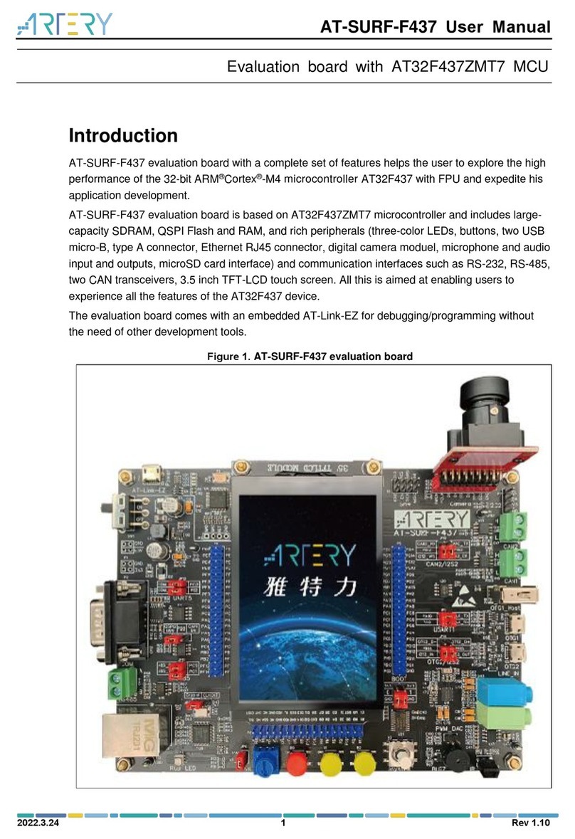
Artery provides AT-SURF-F437 development board, covering most of the advanced functions of
AT32F437, and provides multiple practical programs (stored in BSPrountines\project\at_surf_f437
\examples). For details, refer to AN0049_AT_SURF_F437_Board_Application_Note on Artery's
official website.

AT32F435 & AT32F437 Get Started Guide
2022.4.20 20 Ver 2.0.0
Figure 24. AT-SURF-F437 development board
Note: System performance improvement requires optimization from different aspects. Please refer to
AN0004_Performance_Optimization and AN0092_AT32F435_437_Performance_Improve on Artery's official
website to learn how to improve AT32F435/AT32F437 operation performance.
Other manuals for AT32F435 Series
2
This manual suits for next models
1
Table of contents
Other ARTERY Motherboard manuals

ARTERY
ARTERY AT32-Comm-EV User manual

ARTERY
ARTERY AT32-Video-EV User manual

ARTERY
ARTERY AT-START-F407 User manual

ARTERY
ARTERY AT-START-F403 User manual

ARTERY
ARTERY AT-SURF-F437 User manual

ARTERY
ARTERY AT32F4 Series User manual

ARTERY
ARTERY AT32F415 Series User manual

ARTERY
ARTERY AT-START-F425 User manual

ARTERY
ARTERY AT-START-WB415 User manual