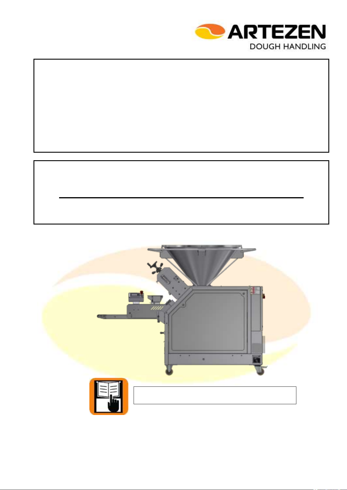
Volumetric Dough Divider Calybra - Calybra L
2/59
Usage and Maintenance Manual (Translation of the original instructions) –MASV7_en_0 dated 01/09/2016
TABLE OF CONTENTS
CE DECLARATION OF CONFORMITY........................................................................................................................................................................... 4
1INTRODUCTION...................................................................................................................................................................................................... 5
1.1 PREAMBLE....................................................................................................................................................................................5
1.2 INSTRUCTIONS AND GENERAL WARNINGS..............................................................................................................................6
1.3 MAIN CASES IN WHICH THE COMPANY DECLINES ANY AND ALL LIABILITY.........................................................................6
1.4 TERMINOLOGY.............................................................................................................................................................................7
1.5 VALIDITy of the ce marking and of the ce declaration of conformity...............................................................................................7
2CHARACTERISTICS OF THE MACHINE............................................................................................................................................................ 8
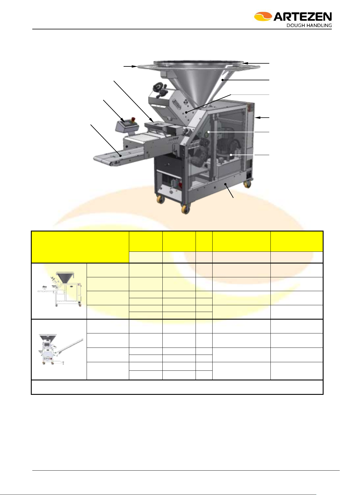
2.1 DESCRIPTION AND INTENDED USE...........................................................................................................................................8
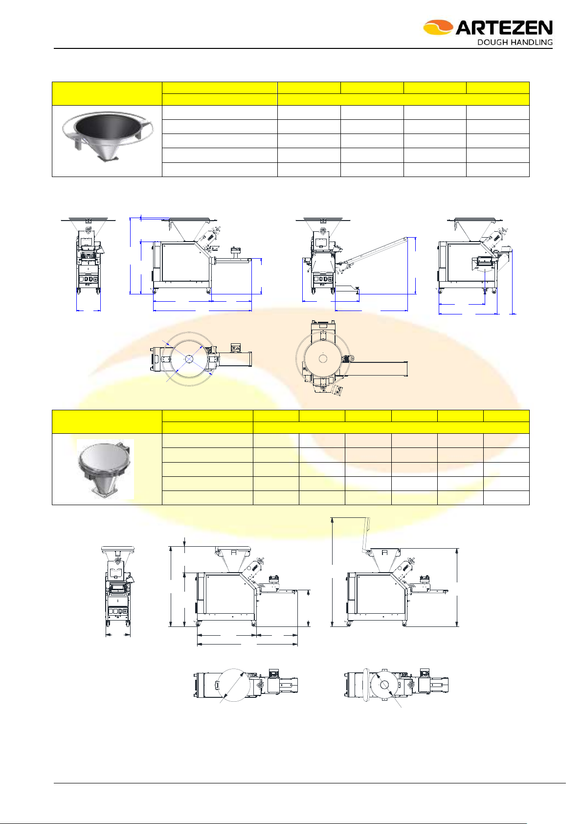
2.2 MODELS, VERSIONS AND CHARACTERISTICS OF THE MACHINE..........................................................................................9
2.3 MAIN SWITCH.............................................................................................................................................................................12
2.4 CONTROL PANEL.......................................................................................................................................................................12
2.4.1 ELECTRO-MECHANICAL CONTROL PANEL ..................................................................................................................................... 12
2.4.2 “TOUCH SCREEN” CONTROL PANEL ................................................................................................................................................. 13
2.4.3 “MEMORY PACK” CONTROL PANEL ................................................................................................................................................... 14
2.4.4 «V» BELT RELATIVE SPEED CONTROL DEVICE............................................................................................................................. 14
2.5 IDENTIFICATION PLATE.............................................................................................................................................................15
3INSTALLATION AND USE................................................................................................................................................................................... 15
3.1 INSTALLATION SITE REQUIREMENTS .....................................................................................................................................15
3.2 TRANSPORT, HANDLING AND POSITIONING ..........................................................................................................................16
3.3 ASSEMBLING/DISSASEMBLING THE SPACER RING...............................................................................................................17
3.4 ASSEMBLY/DISASSEMBLY OF THE FLOUR DUSTER.............................................................................................................21
3.5 ASSEMBLY/DISASSEMBLY OF THE V-BELTS (CALYBRA L - VERSION “INTERNAL V-BELT”) ..............................................22
3.6 ELECTRICAL HOOK-UP..............................................................................................................................................................24
3.7 (HOUSING FOR) AUXILIARY CONNECTION DEVICES.............................................................................................................24
3.8 FIRST START-UP AND CONTROL OF CORRECT MOTOR ROTATION DIRECTION................................................................25
3.9 OPERATION AND USE ...............................................................................................................................................................25
3.9.1 GENERAL INFORMATION OF NORMAL USE.................................................................................................................................... 25
3.9.2 STARTING UP THE MACHINE............................................................................................................................................................... 26
3.9.3 HOW TO USE THE MACHINE................................................................................................................................................................ 27
3.9.4 EMPTYING THE MACHINE..................................................................................................................................................................... 30
3.9.5 POSSIBLE METHODS OF STOPPING AND RESTARTING THE MACHINE................................................................................. 30
3.10 REGULATING THE INCLINATION OF THE PRODUCT OUTPUT BELT.....................................................................................31
3.11 INSTRUCTION AND TRAINING OF THE MACHINE OPERATORS............................................................................................32
4MAINTENANCE..................................................................................................................................................................................................... 33
4.1 INTRODUCTION..........................................................................................................................................................................33
4.2 ROUTINE AND PROGRAMMED MAINTENANCE.......................................................................................................................33
4.3 HYDRAULIC CIRCUIT .................................................................................................................................................................33
4.3.1 FILLING AND/OR REPLACING OIL IN THE HYDRAULIC BLOCK .................................................................................................. 33
4.3.2 OIL TEMPERATURE CONTROL SENSOR.......................................................................................................................................... 35
4.3.3 REPLACING HOSES (extraordinary/routine maintenance) ................................................................................................................ 35
4.4 ROUTINE CLEANING OF THE MACHINE...................................................................................................................................35
4.4.1 CLEANING THE WEIGHT CHAMBER .................................................................................................................................................. 36
4.4.2 CLEANING THE HOPPER....................................................................................................................................................................... 37
4.4.3 CLEANING THE BELTS........................................................................................................................................................................... 37
4.4.4 CLEANING THE HYDRAULIC BLOCK AND THE HEAT EXCHANGER.......................................................................................... 38
4.4.5 CLEANING THE DUST AND RESIDUE COLLECTION DRAWERS................................................................................................. 39
4.4.6 CLEANING THE BELT SCRAPER (OPTIONAL) ................................................................................................................................. 39
4.4.7 CLEANING THE FLOUR DUSTER......................................................................................................................................................... 40
4.5 ELECTRICAL MAINTENANCE ....................................................................................................................................................40
4.7 REPLACING THE MICRO-SWITCHES ASSOCIATED WITH THE HOPPER COVER ................................................................42
4.8 REPLACING THE MICRO-SWITCHES ASSOCIATED WITH THE WEIGHT CHAMBER DOOR ................................................43
4.9 REPLACEMENT PARTS..............................................................................................................................................................46
4.10 PROLONGED SHUT-DOWN OR EXCLUSION FROM SERVICE................................................................................................46
4.11 POTENTIAL BREAKDOWNS AND/OR ANOMALIES ..................................................................................................................46
4.12 DIAGNOSTIC SIGNALS - ALARMS.............................................................................................................................................50
5SAFETY................................................................................................................................................................................................................... 52
5.1 INTRODUCTION..........................................................................................................................................................................52
5.2 DANGERS, SAFETY DEVICES AND RESIDUAL RISKS ............................................................................................................52
5.2.1 DANGERS TYPICAL OF THIS MACHINE ............................................................................................................................................ 52
5.2.2 SAFETY EQUIPMENT OF THIS MACHINE.......................................................................................................................................... 53
5.2.3 CONTROLLING THE EFFICIENCY OF THE SAFETY EQUIPMENT............................................................................................... 54
5.3 RESIDUAL RISKS........................................................................................................................................................................56
5.3.1 MECHANICAL RESIDUAL RISKS.......................................................................................................................................................... 56
5.3.2 RESIDUAL RISKS DUE TO HYDRAULIC PRESSURE...................................................................................................................... 56
5.3.3 RESIDUAL RISKS DUE TO DUST INHALATION................................................................................................................................ 56
5.3.4 RESIDUAL RISKS DUE TO LACK OF HYGIENE................................................................................................................................ 57
5.3.5 RESIDUAL RISKS DUE TO BREACH OF ERGONOMIC PRINCIPLES.......................................................................................... 57
5.3.6 RESIDUAL HEALTH RISKS DUE TO CONTACT WITH OIL............................................................................................................. 57
5.3.7 ELECTRICAL RESIDUAL RISKS ........................................................................................................................................................... 57
5.3.8 RISK OF POLLUTING THE ENVIRONMENT (GROUND).................................................................................................................. 58