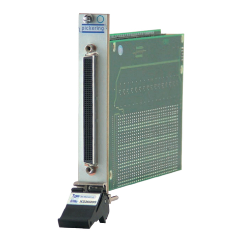
artisan PB1651ADC1 User manual

Artisan Technology Group is your source for quality
new and certied-used/pre-owned equipment
• FAST SHIPPING AND
DELIVERY
• TENS OF THOUSANDS OF
IN-STOCK ITEMS
• EQUIPMENT DEMOS
• HUNDREDS OF
MANUFACTURERS
SUPPORTED
• LEASING/MONTHLY
RENTALS
• ITAR CERTIFIED
SECURE ASSET SOLUTIONS
SERVICE CENTER REPAIRS
Experienced engineers and technicians on staff
at our full-service, in-house repair center
WE BUY USED EQUIPMENT
Sell your excess, underutilized, and idle used equipment
We also offer credit for buy-backs and trade-ins
www.artisantg.com/WeBuyEquipment
REMOTE INSPECTION
Remotely inspect equipment before purchasing with
our interactive website at www.instraview.com
LOOKING FOR MORE INFORMATION?
Visit us on the web at www.artisantg.com for more
information on price quotations, drivers, technical
specications, manuals, and documentation
Contact us: (888) 88-SOURCE | sales@artisantg.com | www.artisantg.com
SM
View
Instra

PB1651ADC1 A/D Module
User’s Guide
Artisan Technology Group - Quality Instrumentation ... Guaranteed | (888) 88-SOURCE | www.artisantg.com

2
Copyright
The data in this document may not be altered or amended without special
notification from ETAS GmbH. ETAS GmbH undertakes no further obligation
in relation to this document. The software described in it can only be used if
the customer is in possession of a general license agreement or single license.
Using and copying is only allowed in concurrence with the specifications
stipulated in the contract.
Under no circumstances may any part of this document be copied, repro-
duced, transmitted, stored in a retrieval system or translated into another
language without the express written permission of ETAS GmbH.
© Copyright 2004 - 2010 ETAS GmbH, Stuttgart
The names and designations used in this document are trademarks or brands
belonging to the respective owners.
R1.0.3 EN - 07.2010 TTN F 00K 103 875
Artisan Technology Group - Quality Instrumentation ... Guaranteed | (888) 88-SOURCE | www.artisantg.com

Contents 3
Contents
1Introduction . . . . . . . . . . . . . . . . . . . . . . . . . . . . . . . . . . . . . . . . . . . . . . . . . . . . . 5
1.1 Applications and Features . . . . . . . . . . . . . . . . . . . . . . . . . . . . . . . . . . . . . 5
1.2 Block Diagram . . . . . . . . . . . . . . . . . . . . . . . . . . . . . . . . . . . . . . . . . . . . . . 7
2Hardware Features . . . . . . . . . . . . . . . . . . . . . . . . . . . . . . . . . . . . . . . . . . . . . . . . 8
2.1 Inputs . . . . . . . . . . . . . . . . . . . . . . . . . . . . . . . . . . . . . . . . . . . . . . . . . . . . 8
2.1.1 Input Voltage Range . . . . . . . . . . . . . . . . . . . . . . . . . . . . . . . . . . 8
2.1.2 Analog Input Channels. . . . . . . . . . . . . . . . . . . . . . . . . . . . . . . . 8
2.1.3 Anti-Aliasing Filter . . . . . . . . . . . . . . . . . . . . . . . . . . . . . . . . . . . 9
2.1.4 External Synchronization Inputs . . . . . . . . . . . . . . . . . . . . . . . . 10
2.1.5 Creating a Mean Value. . . . . . . . . . . . . . . . . . . . . . . . . . . . . . . 10
2.2 Configuration . . . . . . . . . . . . . . . . . . . . . . . . . . . . . . . . . . . . . . . . . . . . . 10
2.3 LEDs . . . . . . . . . . . . . . . . . . . . . . . . . . . . . . . . . . . . . . . . . . . . . . . . . . . . 10
3Pin Assignment. . . . . . . . . . . . . . . . . . . . . . . . . . . . . . . . . . . . . . . . . . . . . . . . . . 12
4Technical Data . . . . . . . . . . . . . . . . . . . . . . . . . . . . . . . . . . . . . . . . . . . . . . . . . . 14
5ETAS Contact Addresses . . . . . . . . . . . . . . . . . . . . . . . . . . . . . . . . . . . . . . . . . . . 17
Index . . . . . . . . . . . . . . . . . . . . . . . . . . . . . . . . . . . . . . . . . . . . . . . . . . . . . . . . . 19
Artisan Technology Group - Quality Instrumentation ... Guaranteed | (888) 88-SOURCE | www.artisantg.com

Contents4
Artisan Technology Group - Quality Instrumentation ... Guaranteed | (888) 88-SOURCE | www.artisantg.com

Introduction 5
1 Introduction
This User's Guide contains the description of the PB1651ADC1 A/D Module.
It consists of the following chapters:
• Introduction
– Applications and Features (section 1.1 on page 5)
– Block Diagram (section 1.2 on page 7)
• Hardware Features (chapter 2 on page 8)
– Configuration (section 2.2 on page 10)
– LEDs (section 2.3 on page 10)
• Pin Assignment (chapter 3 on page 12)
• Technical Data (chapter 4 on page 14)
1.1 Applications and Features
The PB1651ADC1 A/D Module is used to acquire analog signals with average
resolution and data rates (e.g. engine temperature, oil temperature). It can be
used both with the ES1651 Carrier Board (VMEbus) and with the ES4350 Car-
rier Board (VXIbus).
The PB1651ADC1 A/D Module has the following features:
• 16 differential input channels
• One A/D converter per channel with 16-bit resolution
• Accuracy ±3 mV typical, ±5 mV warranted
• Conversion rate/sampling rate 25 kSamples/s
• Input overvoltage protection ±60 V
• Input impedance > 10 MΩ
• 4th order low-pass filter 5 kHz (3 dB cutoff frequency)
Artisan Technology Group - Quality Instrumentation ... Guaranteed | (888) 88-SOURCE | www.artisantg.com

Introduction6
The following figure shows the front panel of the PB1651ADC1 A/D Module.
Fig. 1-1 Front Panel of the PB1651ADC1 A/D Module
RDER CH
INPUT 0-15
ETAS
PB1651
ADC1.1
Artisan Technology Group - Quality Instrumentation ... Guaranteed | (888) 88-SOURCE | www.artisantg.com

Introduction 7
1.2 Block Diagram
The following figure shows the block diagram of the PB1651ADC1 A/D Mod-
ule.
Fig. 1-2 Block Diagram of the PB1651ADC1 A/D Module
Measurement Controller
CH 15
Overvoltage
Protection
Differential
Amplifier
Anti-
Aliasing
4th Order
Lowpass
Filter
A/D
Converter
CH 0
Overvoltage
Protection
Differential
Amplifier
Anti-
Aliasing
4th Order
Lowpass
Filter
A/D
Converter
Artisan Technology Group - Quality Instrumentation ... Guaranteed | (888) 88-SOURCE | www.artisantg.com

Hardware Features8
2 Hardware Features
This section contains a description of the inputs of the PB1651ADC1 A/D Mod-
ule.
2.1 Inputs
2.1.1 Input Voltage Range
The input voltage range of the channels is 0 - 10 V. The analog inputs are pro-
tected against overvoltage to +60 V.
2.1.2 Analog Input Channels
The PB1651ADC1 A/D Module has 16 identical input channels – the structure
of an input stage is shown in Fig. 2-1. The relevant input signal is measured as
a differential signal at a differential amplifier.
Fig. 2-1 Input Channels
Using a differential amplifier makes it possible to realize systems with a partic-
ularly high common-mode rejection ratio (CMRR) – with the PB1651ADC1 A/D
Module this is 95 dB.
+In
-In
-12 V
+12 V
-12 V
+12 V
+
-
Artisan Technology Group - Quality Instrumentation ... Guaranteed | (888) 88-SOURCE | www.artisantg.com

Hardware Features 9
+IN and -IN of all input channels are capacitively coupled to the system hous-
ing.
2.1.3 Anti-Aliasing Filter
Every channel is equipped with an anti-aliasing 4th order low-pass filter the
3 dB cutoff frequency of which is 5 kHz.
Note
If the signal to be measured is not a differential signal but a single-ended
signal, the relevant –IN input at the input connector has to be connected to
AGND.
Note
When sampling at a sampling rate of fA, only those signals can be acquired
without fault which are band-limited and which contain frequency portions
to a maximum of half the sampling rate fA/2 (sampling theorem). To ensure
that the sampling theorem is adhered to, the sampling rate must be at least
10 kHz.
-3 dB
-65 dB
5 kHz 50 kHz
0 dB
Artisan Technology Group - Quality Instrumentation ... Guaranteed | (888) 88-SOURCE | www.artisantg.com

Hardware Features10
2.1.4 External Synchronization Inputs
The PB1651ADC1 A/D Module supports up to six external trigger signals.
These trigger signals are supplied by the ES1651 Carrier Board (VME) or by the
ES4350 Carrier Board (VXI).
The synchronization inputs make it possible to control the measurement in
terms of time. Each channel can be operated either in Auto mode (25 kHz
sampling rate) or in ”Hardware Triggered” mode (can be set in LABCAR-RTC
(Real-Time Execution Connector)). Only one of the six possible external triggers
can be selected from all 16 channels.
The measure value is always acquired on a positive edge of the trigger signal.
The maximum delay time until a measure value is acquired after a positive edge
of the trigger signal is 40 µs.
2.1.5 Creating a Mean Value
The PB1651ADC1 A/D Module supports the creation of a mean value (e.g. for
noise suppression) over 2, 4, 8, 16, 32, 64 and 128 measure values. A setting
is made in the LABCAR-RTC as to whether a mean value is created and if so,
over how many values. The mean value itself, however, is created in the hard-
ware module which ensures a very high performance.
2.2 Configuration
The inputs are configured and controlled via LABCAR-RTC and LABCAR-OPER-
ATOR. A hardware configuration of the module is not necessary.
2.3 LEDs
There are 3 LEDs on the front panel of the PB1651ADC1 A/D Module, the
meaning of which is described below.
Fig. 2-2 LEDs on the Front Panel
RDER CH
Artisan Technology Group - Quality Instrumentation ... Guaranteed | (888) 88-SOURCE | www.artisantg.com

Hardware Features 11
The LEDs of the PB1651ADC1 A/D Module have the following significance.
Driving the ”CH” LED
The driving source of the ”CH” LED can be configured in the software – one
of the 16 input channels or ”RTIO” can be set as the driving source.
If an input channel is set as the driving source, the LED lights up when the
channel level is high and does not light up when the channel level is low. If
”RTIO” is set as the driving source, the LED can be powered on/off by the
simulation model.
The ”LED Driving Source” parameter is described in the Real-Time Execution
Connector (LABCAR-RTC) User’s Guide.
Display of the Version Number of the I/O Modules
When the signal box is powered on, the I/O modules show the version number
via the ”RD” and ”CH” LEDs. The version number consists of three parts (e.g.
2.1.3). First of all, the ”RD” LED flashes twice (”CH” LED off). Then the ”RD”
LED flashes once (”CH” LED lights up). Then the ”RD” LED flashes three times
(”CH” LED off).
After the version number of the relevant I/O module has been displayed, the
two LEDs, ”RD” and ”CH”, go out and take on the relevant function of the I/O
module used.
LED Color Meaning
ER Red Error
RD Green Ready
CH Green Can be configured using the software (see the
section ”Driving the ”CH” LED” later in this chap-
ter)
Tab. 2 -1 Significance of the LEDs
Artisan Technology Group - Quality Instrumentation ... Guaranteed | (888) 88-SOURCE | www.artisantg.com

Pin Assignment12
3PinAssignment
This section describes the pin assignment of the PB1651ADC1 A/D Module.
The connector for the signal inputs is a DSub62HD connector (male). The
shielding is at front panel and housing potential and thus at protective earth.
Fig. 3-1 Front-Facing Connector of the PB1651ADC1 A/D Module (View
from the Plug-In Side)
43
42
22
21
1
62
Artisan Technology Group - Quality Instrumentation ... Guaranteed | (888) 88-SOURCE | www.artisantg.com

Pin Assignment 13
The following table contains the connector pin assignment.
Pin Signal Pin Signal Pin Signal
1 +IN_CH0 22 AGND 43 -IN_CH0
2 +IN_CH1 23 AGND 44 -IN_CH1
3 +IN_CH2 24 AGND 45 -IN_CH2
4 +IN_CH3 25 AGND 46 -IN_CH3
5 +IN_CH4 26 AGND 47 -IN_CH4
6 +IN_CH5 27 AGND 48 -IN_CH5
7 +IN_CH6 28 AGND 49 -IN_CH6
8 +IN_CH7 29 AGND 50 -IN_CH7
9 +IN_CH8 30 AGND 51 -IN_CH8
10 +IN_CH9 31 AGND 52 -IN_CH9
11 +IN_CH10 32 AGND 53 -IN_CH10
12 +IN_CH11 33 AGND 54 -IN_CH11
13 +IN_CH12 34 AGND 55 -IN_CH12
14 +IN_CH13 35 AGND 56 -IN_CH13
15 +IN_CH14 36 AGND 57 -IN_CH14
16 +IN_CH15 37 AGND 58 -IN_CH15
17 NC 38 AGND 59 NC
18 NC 39 AGND 60 NC
19 NC 40 AGND 61 NC
20 NC 41 AGND 62 NC
21 AGND 42 AGND
Tab. 3 - 1 Pin Assignment
Artisan Technology Group - Quality Instrumentation ... Guaranteed | (888) 88-SOURCE | www.artisantg.com

Tec h nical D a t a14
4TechnicalData
This section contains the technical data of the PB1651ADC1 A/D Module in
tabular form.
Inputs
Power Supply
Environmental Conditions
Number of inputs 16
Input voltage V+IN -10 V...+10 V
Input voltage V-IN -10 V...+10 V
Voltage between V-IN and V+IN 0 V...+10 V
Overvoltage protection ±60 V
Input impedance >10 MΩ
Resolution 152 µV (16 Bit)
Accuracy ±3 mV typical
±5 mV warranted
Sampling rate (internal synch. mode) 25 kSamples/s
Sampling rate (external synch. mode) Max. 12.5 kSamples/s
Ext. Trigger - minimum high time 40 µs
Ext. Trigger – maximum delay time 40 µs
Current consumption 300 mA @ +5 V DC
200 mA @ +12 V DC
200 mA @ -12 V DC
100 mA @ +3.3 V DC
Operating temperature 5 °C to 35 °C (5.00 °C to 35.00 °C)
Relative humidity 0 to 95% (non-condensing)
Artisan Technology Group - Quality Instrumentation ... Guaranteed | (888) 88-SOURCE | www.artisantg.com

Technical Data 15
Physical Dimensions
Printed circuit board (L x W) 145 mm x 100 mm
Front panel Height: 3 U
Width: 4 HP
Artisan Technology Group - Quality Instrumentation ... Guaranteed | (888) 88-SOURCE | www.artisantg.com

Tec h nical D a t a16
Artisan Technology Group - Quality Instrumentation ... Guaranteed | (888) 88-SOURCE | www.artisantg.com

ETAS Contact Addresses 17
5 ETAS Contact Addresses
ETAS HQ
ETAS GmbH
ETAS Subsidiaries and Technical Support
For details of your local sales office as well as your local technical support team
and product hotlines, take a look at the ETAS website:
Borsigstraße 14 Phone: +49 711 89661-0
70469 Stuttgart Fax: +49 711 89661-106
Germany WWW: www.etas.com
ETAS subsidiaries WWW: www.etas.com/en/contact.php
ETAS technical support WWW: www.etas.com/en/hotlines.php
Artisan Technology Group - Quality Instrumentation ... Guaranteed | (888) 88-SOURCE | www.artisantg.com

ETAS Contact Addresses18
Artisan Technology Group - Quality Instrumentation ... Guaranteed | (888) 88-SOURCE | www.artisantg.com

Index 19
Index
A
Analog input channels 8
Anti-aliasing filter 9
B
Block diagram 7
C
Configuration 10
Creating a mean value 10
E
ETAS Contact Addresses 17
External synchronization inputs 10
H
Hardware features 8
I
Input voltage range 8
Inputs 8
Introduction 5
L
LEDs 10
P
Pin assignment 12
T
Technical data 14
V
Version number 11
Artisan Technology Group - Quality Instrumentation ... Guaranteed | (888) 88-SOURCE | www.artisantg.com
Table of contents
Other artisan Control Unit manuals