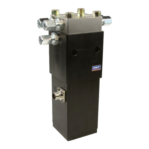
SKF BCU User manual

Installation, operation and maintenance manual
BCU control unit
Read this manual before installing,
operating or maintaining this actuator.
Failure to follow safety precautions and
instructions could cause actuator failure
and result in serious injury, death or
property damage.

® SKF is a registered trademark of the SKF Group.
© SKF Group
The contents of this publication are the copyright of the publisher and may not be reproduced (even
extracts) unless prior written permission is granted. Every care has been taken to ensure the accuracy
of the information contained in this publication but no liability can be accepted for any loss or damage
whether direct, indirect or consequential arising out of the use of the information contained herein.
PUB MT/P EN · December
Certain image(s) used under license from Shutterstock.com.

Table of content
SKF – the knowledge engineering company. . . . . . .
Basic Principles . . . . . . . . . . . . . . . . . . . . . . . . . . .
. Introduction. . . . . . . . . . . . . . . . . . . . . . . . . . . .
Operating Instructions . . . . . . . . . . . . . . . . . . . . . . . . . . .
Validity . . . . . . . . . . . . . . . . . . . . . . . . . . . . . . . . . . . . . .
Target Audience. . . . . . . . . . . . . . . . . . . . . . . . . . . . . . .
Summary of Contents . . . . . . . . . . . . . . . . . . . . . . . . . . .
Organizational Measures . . . . . . . . . . . . . . . . . . . . . . . . .
Location of the operating manual. . . . . . . . . . . . . . . . .
Conventions . . . . . . . . . . . . . . . . . . . . . . . . . . . . . . . . . . .
Warning and usage instructions . . . . . . . . . . . . . . . . . .
Position numbers and referencing . . . . . . . . . . . . . . . .
Safety . . . . . . . . . . . . . . . . . . . . . . . . . . . . . . . .
Safety Program. . . . . . . . . . . . . . . . . . . . . . . . . . . . . . . . .
Purpose of use of the BCU control unit. . . . . . . . . . . . .
Intended use . . . . . . . . . . . . . . . . . . . . . . . . . . . . . . . . .
Unintended use. . . . . . . . . . . . . . . . . . . . . . . . . . . . . . .
User groups. . . . . . . . . . . . . . . . . . . . . . . . . . . . . . . . . .
Operating modes. . . . . . . . . . . . . . . . . . . . . . . . . . . . .
Danger zones . . . . . . . . . . . . . . . . . . . . . . . . . . . . . . .
Areas of responsibility. . . . . . . . . . . . . . . . . . . . . . . . .
Specific dangers . . . . . . . . . . . . . . . . . . . . . . . . . . . . . . .
. Safety EMC . . . . . . . . . . . . . . . . . . . . . . . . . . .
Manufacturer’s declaration of EMC compliance . . . . .
Instructions for use / General . . . . . . . . . . . . . . . . . . . . .
Professional healthcare facility environment . . . . . . .
Essential performance . . . . . . . . . . . . . . . . . . . . . . . .
RF communications equipments . . . . . . . . . . . . . . . . . .
Technical description . . . . . . . . . . . . . . . . . . . . . .
Requirements applicable to all ME equipment
and ME Systems Compliance for each Emission
and Immunity standards. . . . . . . . . . . . . . . . . . . . . . .
Emission guidance . . . . . . . . . . . . . . . . . . . . . . . . . . .
Instruction for maintaining BASIC Safety and
Essential performance for the expected Service life . . .
One time approved in the final application not
change it allowed due to the EMC influence . . . . . . . .
. Structure and function . . . . . . . . . . . . . . . . . . .
Structure. . . . . . . . . . . . . . . . . . . . . . . . . . . . . . . . . . . . .
Function . . . . . . . . . . . . . . . . . . . . . . . . . . . . . . . . . . . . .
Options and Accessories . . . . . . . . . . . . . . . . . . . . . . . . .
. Normal Operation . . . . . . . . . . . . . . . . . . . . . .
Preconditions for operation . . . . . . . . . . . . . . . . . . . . . .
BCU control unit Powering on . . . . . . . . . . . . . . . . . . . .
Shutting down . . . . . . . . . . . . . . . . . . . . . . . . . . . . . . . .
. Special Operations . . . . . . . . . . . . . . . . . . . . . .
Installation and Initial Start-Up . . . . . . . . . . . . . . . . . . .
Preparation. . . . . . . . . . . . . . . . . . . . . . . . . . . . . . . . . . .
Transport. . . . . . . . . . . . . . . . . . . . . . . . . . . . . . . . . . .
Check the supply schedule . . . . . . . . . . . . . . . . . . . . .
Energy supply . . . . . . . . . . . . . . . . . . . . . . . . . . . . . . .
Installation and connections. . . . . . . . . . . . . . . . . . . . . .
Erection and alignment. . . . . . . . . . . . . . . . . . . . . . . .
Process: Connect the operating device. . . . . . . . . . . .
Process: Connecting the actuator unit . . . . . . . . . . . .
Process: Mount the safety protective cover . . . . . . . .
Process: Connect ground wire . . . . . . . . . . . . . . . . . .
Installation. . . . . . . . . . . . . . . . . . . . . . . . . . . . . . . . . .
Initial Start-Up . . . . . . . . . . . . . . . . . . . . . . . . . . . . . . . .
Installation inspection. . . . . . . . . . . . . . . . . . . . . . . . .
Commissioning . . . . . . . . . . . . . . . . . . . . . . . . . . . . . .
. Maintenance, Clearing Malfunctions, Repair . . .
Maintenance . . . . . . . . . . . . . . . . . . . . . . . . . . . . . . . . . .
Maintenance plan . . . . . . . . . . . . . . . . . . . . . . . . . . . .
Cleaning. . . . . . . . . . . . . . . . . . . . . . . . . . . . . . . . . . . .
Malfunctions . . . . . . . . . . . . . . . . . . . . . . . . . . . . . . . . . .
Fault rectification. . . . . . . . . . . . . . . . . . . . . . . . . . . . .
Repair . . . . . . . . . . . . . . . . . . . . . . . . . . . . . . . . . . . . .
. Removing from Service, Dismantling
and Disposal . . . . . . . . . . . . . . . . . . . . . . . . . . . .
Shutting down. . . . . . . . . . . . . . . . . . . . . . . . . . . . . . .
Dismantling. . . . . . . . . . . . . . . . . . . . . . . . . . . . . . . . .
Storage . . . . . . . . . . . . . . . . . . . . . . . . . . . . . . . . . . . .
Disposal. . . . . . . . . . . . . . . . . . . . . . . . . . . . . . . . . . . .
. Appendix . . . . . . . . . . . . . . . . . . . . . . . . . . . . .
Technical Data . . . . . . . . . . . . . . . . . . . . . . . . . . . . . . .
Device Data . . . . . . . . . . . . . . . . . . . . . . . . . . . . . . . . .
Operating data . . . . . . . . . . . . . . . . . . . . . . . . . . . . . .
Ambient conditions . . . . . . . . . . . . . . . . . . . . . . . . . . .
Plans and Schemes. . . . . . . . . . . . . . . . . . . . . . . . . . .
From one simple but
inspired solution to
a misalignment
problem in a textile
mill in Sweden, and
fifteen employees in
1907, SKF has
grown to become a
global industrial
knowledge leader.
Over the years, we have built on our exper-
tise in bearings, extending it to seals, mecha-
tronics, services and lubrication systems.
Our knowledge network includes 46 000
employees, 15 000 distributor partners,
offices in more than 130 countries, and a
growing number of SKF Solution Factory
sites around the world.
Research and development
We have hands-on experience in over forty
industries based on our employees’ know-
ledge of real life conditions. In addition, our
world-leading experts and university part-
ners pioneer advanced theoretical research
and development in areas including tribol-
ogy, condition monitoring, asset manage-
ment and bearing life theory. Our ongoing
commitment to research and development
helps us keep our customers at the forefront
of their industries.
Meeting the toughest challenges
Our network of knowledge and experience,
along with our understanding of how our
core technologies can be combined, helps
us create innovative solutions that meet the
toughest of challenges. We work closely with
our customers throughout the asset life
cycle, helping them to profitably and
responsibly grow their businesses.
SKF Solution Factory makes SKF knowledge and manufacturing expertise
available locally to provide unique solutions and services to our customers.
Working with SKF IT and logistics systems and application experts, SKF
Authorized Distributors deliver a valuable mix of product and application
knowledge to customers worldwide.
Working for a sustainable future
Since 2005, SKF has worked to reduce the
negative environmental impact from our
operations and those of our suppliers. Our
continuing technology development resulted
in the introduction of the SKF BeyondZero
portfolio of products and services which im-
prove efficiency and reduce energy losses,
as well as enable new technologies har-
nessing wind, solar and ocean power. This
combined approach helps reduce the envir-
onmental impact both in our operations and
our customers’ operations.
SKF – the knowledge engineering
company

Bearings
SKF is the world leader in the design, development
and manufacture of high performance rolling
bearings, plain bearings, bearing units and
housings.
Machinery maintenance
Condition monitoring technologies and main-
tenance services from SKF can help minimize
unplanned downtime, improve operational
efficiency and reduce maintenance costs.
Sealing solutions
SKF offers standard seals and custom engineered
sealing solutions to increase uptime, improve
machine reliability, reduce friction and power
losses, and extend lubricant life.
Mechatronics
SKF fly-by-wire systems for aircraft and drive-by-
wire systems for off-road, agricultural and forklift
applications replace heavy, grease or oil consuming
mechanical and hydraulic systems.
Lubrication solutions
From specialized lubricants to state-of-the-art
lubrication systems and lubrication management
services, lubrication solutions from SKF can help to
reduce lubrication related downtime and lubricant
consumption.
Actuation and motion control
With a wide assortment of products – from actu-
ators and ball screws to profile rail guides – SKF
can work with you to solve your most pressing
linear system challenges.
Our knowledge
– your success
SKF Life Cycle Management is how we combine our technology
platforms and advanced services, and apply them at each stage
of the asset life cycle, to help our customers to be more
successful, sustainable and profitable.
Working closely with you
Our objective is to help our customers
improve productivity, minimize mainten-
ance, achieve higher energy and resource
efficiency, and optimize designs for long
service life and reliability.
Innovative solutions
Whether the application is linear or rotary
or a combination, SKF engineers can work
with you at each stage of the asset life cycle
to improve machine performance by looking
at the entire application. This approach
doesn’t just focus on individual components
like bearings or seals. It looks at the whole
application to see how each component in-
teracts with each other.
Design optimization and verification
SKF can work with you to optimize current
or new designs with proprietary 3-D mod-
elling software that can also be used as a
virtual test rig to confirm the integrity of the
design.
SKF Life Cycle
Management
D
e
s
i
g
n
a
n
d
d
e
v
e
l
o
p
M
a
n
u
f
a
c
t
u
r
e
a
n
d
t
e
s
t
S
p
e
c
i
f
i
c
a
t
i
o
n
I
n
s
t
a
l
l
a
n
d
c
o
m
m
i
s
s
i
o
n
O
p
e
r
a
t
e
a
n
d
m
o
n
i
t
o
r
M
a
i
n
t
a
i
n
a
n
d
r
e
p
a
i
r

Basic Principles
The following chapters are part of the basic principles:
Introduction, page
Safety, page
Structure and function, page
. Introduction
This chapter contains information on the structure and cate-
gorization of the operating manual. It simplifies the handling
of the operating manual and facilitates fast access to the
desired information.
Operating Instructions
SKF Actuation System (Lieastal) AG manufactures state-of-
the-art electric actuators, control units and operating
equipment.
The object of this operating manual is to give you, the user, an
introduction to correct and safe use.
In order to make it possible to reach this objective, it is imper-
ative that you should read the chapter Safety († . Safety,
page ) carefully and follow the instructions in this operating
manual.
Validity
The instructions in this manual refer to the linear actuator
BCU control unit with the following identification:
• Manufacturer: SKF
• Product name: BCU control unit
• Type designation: BCUxx-xxx xxx-xxxx
• Year of manufacturer:
• CE-mark: according to the technical documentation
Target Audience
The operating manual is intended for technical personnel and
authorized users who use the BCU control unit in their prod-
ucts and work with them. The Operating Authority determines
who is authorized as the user.
We distinguish between different user groups, as the require-
ments on the users vary, depending on the activity they
perform.

NOTE: you will find definitions of the user groups along with
their corresponding requirements in the chapter on safety
(† . Safety, page ). You can assume one or more of these
user groups provided you meet the applicable requirements.
The organization and implementation of the operating
instructions takes into account the different user groups.
Summary of Contents
The operating instructions serve as a reference work. The
information therein is organized into four task- and
theme-related parts:
Basic Principles
Normal
Operation
Special
Operations
Appendix
The Basic Principles section gives the basic knowledge that
every user should have.
The Appendix contains information that the user has to be
able to access at any time. This includes information on
using the operating instructions (indexes) as well as data
concerning the product itself (technical data).
Aids for accessing information
This manual has access aids that make it easier for you to
quickly access the desired information:
• You can most easily find all information on a given topic
from the Table of Contents, thanks to the task and
theme-related organization of the operating instructions.
• Information on a certain activity or a special topic can be
found most quickly through the Index.
• Within the chapters of the operating instructions, you can
orient yourself with the help of the margin notes.
The Special Operations section describes all jobs deviating
from normal operation, such as installation, initial start-up,
maintenance, fixing faults and doing repairs.
The Normal Operation section contains information needed
for operating the product under normal conditions, i.e.
undisrupted operation for use according to its intended
application.

Organizational Measures
In case of questions to which answers cannot be found in the
operating manual, please directly contact the manufacturer.
Location of the operating manual
The operating manual can only be of any use to you if you
have access to it at all times. Therefore, always keep it accessi-
ble near the machine.
Conventions
In this operating manual, we use some abbreviations and
markings for identifying text sections or notes. The depiction
conventions are described in the following paragraphs.
Warning and usage instructions
Please note the significance of the following warning and
usage instructions:
NOTE: Pointers to usage information that understand the
user to use the product in a technically correct and efficient
manner or understand the properties of the product.
CAUTION
Warnings for instructing the user on the residual dangers to persons
and property that remain owing to the incomplete efficacy of the pro-
tective measures; note regarding special training and personal pro-
tection equipment that may be required.
WARNING
Warnings regarding irreparable damage to persons and property that
have been found to exist on the basis of the danger analysis. With a
pointer regarding protective measures and any special training and
personal protection equipment that may be required.
Position
numbers
Cross-references
to text positions
Position numbers and referencing
We number parts in diagrams in serial order in the clockwise
direction, with unique numbers.
Introduction
We put references to chapters or figures in brackets. They
contain the corresponding chapter number or figure number.

Safety
This chapter targets all the users of the BCU control unit. It
contains information on safe use and optimum utilization.
Safety Program
The safety concept of the Magnetic Elektromotoren AG regu-
lates the authorization for use and the responsibilities of the
individual users.
The BCU control unit is constructed and built according to the
state-of-the-art and the recognized technical rules of safety.
EG-conformance is documented with the technical
documentation.
Purpose of use of the BCU control unit
The BCU control unit has been designed and constructed for
use in accordance with its intended purpose-conformant use.
If you use the BCU control unit for any use other than the use
described, the manufacturer cannot be held liable for damage
that results therefrom.
Intended use
The authorized use of the BCU control unit is the:
• Controlling of a maximum of three actuators for pressure or
tension-stressed strokes.
NOTE: The operations data can be obtained from chapter
Appendix of this operating manual (†Operating data,
page ) and are only valid for the use with Actuators from
SKF.
Unintended use
Control unit BCU are suitable for indoor use only and must not
be exposed to weathering, strong radiation fields, corrosive or
explosive atmospheric media (†Ambient condition, see
operating conditions page )
NOTE: Any authorized use of the device can cause personal
injury and property damage. Always adhere to the instruction
given in the manual.
User groups
To ensure safety, we place requirements on the users of the
BCU control unit, that must be adhered to under all circum-
stances. Only persons who meet the requirements are enti-
tled to use the BCU control unit.

We refer to all persons who operate, use, commission the
control unit, process it further or pass it on for further pro-
cessing as user groups. As the requirements of these user
groups strongly depend on their role, we distinguish between
the following user groups:
Safety
Operating
Authority
Persons
Device
Executor
Reseller
Operator
Technician
The danger zone covering persons includes, apart from the
actual users, third parties as well (other personnel, visitors,
patients etc.). In cases of damage, the liability is that of the
Operating Authority.
The operating authority is the contractual partner of the
executor or the reseller. They can impose legal conditions on
the operating authority when purchasing the control unit. The
operating authority ensures that the user is instructed on the
authorized use of the equipment.
The executor is the contractual partner of the reseller or the
manufacturer. He assembles the control unit into a total
device. He is authorized by the manufacturer of the BCU con-
trol unit to use the control unit in accordance with the regula-
tions and has the necessary expert knowledge.
The technician has the professional technical training to
implement the BCU control unit according to its authorized
use. Besides the chapter Safety, he is also familiar with the
chapter Special operating modes. He finds the necessary
technical characteristic data in the Annex.
The reseller forwards the machine.
Every other person who uses the BCU control unit we define
as an operator. The operator must have read the Safety chap-
ter in this manual before using the machine. Moreover, he
must be instructed about the normal operation by the operat-
ing authority.
Operating modes
intermittent The BCU control unit is exclusively intended for
intermittent operation (†Technical Data, page 34).
Danger zones
We differentiate between two danger zones that must be
observed, depending on user group.
The danger zone device comes under the user group Executor
and Technician and covers the BCU control unit and all the
mounted-on devices.

Safety
Operating
Authority
Executor
Technician
Operator
Reseller
The operator ensures that nobody is endangered owing to the
operation of the BCU control unit. In particular, he is responsi-
ble for:
• Operation of the BCU control unit in normal operation
• Immediate and specification-conformant reaction to faults
Areas of responsibility
There are different areas of responsibility, corresponding to
the different user groups.
The Operating Authority has the responsibility for the danger
zone covering Persons and ensures that only authorized and
instructed users work with the BCU control unit. He is respon-
sible for the following points:
• Determining the persons who may use the BCU control unit
(authorized persons)
• Instruction of the users
• Compliance with all the relevant legal conditions and
specifications
NOTE: The Operating Authority may only authorize such per-
sons for using the BCU control unit, who conform to the
requirements for the user roles.
The reseller is responsible for the following points:
• Passing on this operating manual and the BCU control unit
to the executor or the
• Passing on of a CE-conformant operating manual and the
device in which the BCU control unit has been integrated to
the Operating Authority.
The executor is responsible for the following points:
• Generation of a CE-conformant operating manual of the
device in which the BCU control unit has been integrated
• Adherence to the safety requirements in accordance with
this operating manual.
The technician is responsible for the following points:
• Compliance with the instructions of the manufacturer and
safe designing of the interfaces to other devices.
• Installation and use of the BCU control unit in accordance
with its intended purpose-conformant use
• Installation of optional modules and connecting cables

Safety
WARNING
The control units BCU do not have an on/off switch and if required to
be switched off, for example in an emergency, the control unit must be
disconnected fro the power supply, Only this measure will de-energize
the control units. Applications where the control units are built in must
provide an emergency stop switch or isolation from the mains supply
on all poles. Additional protective means might be necessary in case of
battery options.
Specific dangers
The following section lists the residual risks that have been
determined by risk assessment. The manufacturer has con-
structively, and with protective measures, minimized the
effects of existing hazards. Pay attention to the residual haz-
ards and potential countermeasures described in the follow-
ing chapters.
CAUTION
Take care not to damage the BCU control unit from water jets. The BCU
control unit is protected against powerful water according to IPX.
WARNING
Warning regarding electrical shock owing to damaged plugs or damaged
network cables. Never touch a damaged network plug or a damaged
network cable when the BCU control unit is running, since the BCU con-
trol unit are supplied V AC or V AC.
• Ensure, before you pull a defective plug out of the plug socket, that the
current fuse is cut off.
CAUTION
Please be aware of damage to people or property as the result of incor-
rect operation. Incorrect operation can endanger people in the danger
zone or objects.
• Before pressing a button on the operating unit, ensure that you press
the right bottom.
• Take appropriate measures to ensure that the operating unit cannot
be operated.
CAUTION
No function is considered as a safe condition.

. Safety EMC
Manufacturer’s declaration of EMC
compliance
IEC --: Medical Electrical Equipment, Part –:
General requirements for basic safety and essential perfor-
mance – Collateral Standard: Electromagnetic disturbances
– Requirements and tests
Instructions for use / General
Professional healthcare facility environment
Physician offices, dental offices, clinics, limited care facilities,
freestanding surgical centers, freestanding birthing centers,
multiple treatment facilities, hospitals (emergency rooms,
PATIENT rooms, intensive care, surgery rooms, except near
HF SURGICAL EQUIPMENT, an MR system outside a RF
shielded room of an ME SYSTEM for magnetic resonance
imaging)
Essential performance
Control of electromechanical actuators
WARNING
The use of this equipment adjacent to or stacked with other equip-
ment should be avoided because it could result improper operation. If
such use is necessary, this equipment and the other equipment
should be observed to verify that they are operating normally.
WARNING
The use of accessories and cables other than those for which the con-
trol unit BCU was designed, can significantly degrade electromagnetic
EMISSIONS and IMMUNITY performance
Description Drawing No. Type Lenqth
Mains cable straiqht / pol /Euro ¥, mm, m
Mains cable straiqht / pol /British ¥, mm, m
Mains cable straiqht / pol / UL ¥AWG , m
Mains cable straiqht / pol / British ¥, mm, m
Mains cable straiqht / pol /Hospital gr ¥AWG , m
Mains cable straiqht / pol / Schuko ¥, mm, m
List of cables, Length of cables, accessories

Technical description
Requirements applicable to all ME
equipment and ME Systems Compliance for
each Emission and Immunity standards
Emission guidance
The control unit BCU is intended for use in the electromag-
netic environment specified below. The customer or user of
the control box should ensure that they are used in such an
environment
Safety EMC
Accessories Part No. Remark
EHA any Passive element (only switches inside); configured with any
cable , m length ¥AWG
STJ any cable ¥AWGS
STE any cable ¥AWGS
Description Ports BCU / Class I Drawing No. Type Lenqth
Handswitch cable straiqht ¥AWG , m
Motor cable straiqht DIN Sp Runner ¥AWG , m
Motor cable straight DIN Sp Runner with
two Hall sensor
¥AWG and
¥AWG
, m
Motor cable straight DIN Sp ECO ¥AWGlS , m
Mains cable straight DIN Sp MAX ¥AWGlS , m
Mains cable coiled DIN Sp MAX ¥AWG , m
Description Ports BCU / Class II Drawing No. Type Lenqth
Handswitch cable straiqht ¥AWG , m
Motor cable straiqht DIN Sp Runner ¥AWG , m
Motor cable straight DIN Sp Runner with
two Hall sensor
¥AWG and
¥AWG
, m
Motor cable straiqht DIN Sp ECO ¥AWG , m
Mains cable straiqht DIN Sp MAX ¥ AWGlS , m
Mains cable coi led DIN Sp MAX ¥AWG , m
RF communications equipments
WARNING
Portable RF communications equipment (including peripherals such as
antenna cables and external antennas) should be used no closer than
cm to any part of the ME equipment. Otherwise, degradation of the
performance of this equipment could result

Emission test Compliance Electromagnetic environment-guidance
RF emission CISPR Group
RF emission CISPR Class B ME equipment class B
Harmonic emission IEC -- Class A Harmonic current limit
Voltage fluctuation/ flicker emis-
sions IEC --
Complies
Instruction for maintaining
BASIC Safety and Essential
performance for the expected
Service life
NOTE: Do not change the once installed final application due
to EMC view Immunity test levels (IEC --:)
WARNING
This product was tested against actual conditions of frequency wireless
environment present in Europe
Safety EMC
Enclosure port
Phenomenon Basic EMC standard or
test method
Immunity test levels
Professional healthcare
facility environment
Home healthcare
Environment
Electrostatic discharge IEC -- ± kV contact
± kV, ± kV, ± kV, ± kV air
Radiated RF EM fields) IEC -- V/m)
MHz – , GHz)
% AM at kHz)
V/m)
MHz – , GHz)
% AM at kHz)
Proximity fields from RF wireless
communications equipment
IEC -- See ..
Rated power frequency magnetic fields) ) IEC -- A/m)
Hz or Hz
) The interface between the PATIENT physiological signal simulation, if used, and the ME EQUIPMENT or ME SYSTEM shall
be located within , m of the vertical plane of the uniform field area in one orientation of the ME EQUIPMENT or ME
SYSTEM.
) ME EQUIPMENT and ME SYSTEMS that intentionally receive RF electromagnetic energy for the purpose of their operation
shall be tested at the frequency of reception. Testing may be performed at other modulation frequencies identified by the
RISK MANAGEMENT PROCESS. This test assesses the BASIC SAFETY and ESSENTIAL PERFORMANCE of an intentional
receiver when an ambient signal is in the passband. It is understood that the receiver might not achieve normal reception
during the test.
) Testing may be performed at other modulation frequencies identified by the RISK MANAGEMENT PROCESS.
) Applies only to ME EQUIPMENT and ME SYSTEMS with magnetically sensitive components or circuitry.
) During the test, the ME EQUIPMENT or ME SYSTEM may be powered at any NOMINAL input voltage, but with the same
frequency as the test signal (see Table ).
) Before modulation is applied.
) This test level assumes a minimum distance between the ME EQUIPMENT or ME SYSTEM and sources of power fre-
quency magnetic field of at least cm. If the RISK ANALYSIS shows that the ME EQUIPMENT or ME SYSTEM will be used
closer than cm to sources of power frequency magnetic field, the IMMUNITY TEST LEVEL shall be adjusted as appropri-
ate for the minimum expected distance.

Input a.c. power port
Phenomenon Basic EMC standard Immunity test levels
Professional healthcare
facility environment
Home healthcare
Environment
Electrical fast transients / bursts ) ) ) IEC -- ± kV
kHz repetition frequency
Surges ) ) ) )
Line-to-line
IEC -- ±, kV, ± kV
Surges ) ) ) ) )
Line-to-ground
IEC -- ±, kV, ± kV, ± kV
Conducted disturbances induced by
RF fields ) ) )
IEC -- V )
, MHz – MHz
V ) in ISM bands
between , MHz and
MHz )
% AM at kHz )
V )
, MHz – MHz
V ) in ISM and ama-
teur radio bands between
, MHz and MHz )
% AM at kHz )
Voltage dips ) ) ) IEC -- % UT; , cycle )
At °, °, °, °, °, °, ° and ° )
% UT; cycle
and
% UT; / cycles )
Single phase: at °
Voltage interruptions ) ) ) ) IEC -- % UT; / cycle )
) The test may be performed at any one power input voltage within the ME EQUIPMENT or ME SYSTEM RATED voltage
range. If the ME EQUIPMENT or ME SYSTEM is tested at one power input voltage, it is not necessary to re-test at addi-
tional voltages.
) All ME EQUIPMENT and ME SYSTEM cables are attached during the test.
) Calibration for current injection clamps shall be performed in a system.
) If the frequency stepping skips over an ISM or amateur band, as applicable, an additional test frequency shall be used in
the ISM or amateur radio band.This applies to each ISM and amateur radio band within the specified frequency range.
) Testing may be performed at other modulation frequencies identified by the RISK MANAGEMENT PROCESS.
) ME EQUIPMENT and ME SYSTEMS with a d.c. power input intended for use with a.c.-to-d.c. converters shall be tested
using a converter that meets the specifications of the MANUFACTURER of the ME EQUIPMENT or ME SYSTEM. The
IMMUNITY TEST LEVELS are applied to the a.c. power input of the converter.
) Applicable only to ME EQUIPMENT and ME SYSTEMS connected to single-phase a.c. mains.
) E.g.
/ means periods at Hz or periods at Hz.
) ME EQUIPMENT and ME SYSTEMS with RATED input current greater than A / phase shall be interrupted once for
/ cycles at any angle and at all phases at the same time (if applicable). ME EQUIPMENT and ME SYSTEMS with
battery backup shall resume line power operation after the test. For ME EQUIPMENT and ME SYSTEMS with RATED input
current not exceeding A, all phases shall be interrupted simultaneously.
) ME EQUIPMENT and ME SYSTEMS that do not have a surge protection device in the primary power circuit may be tested
only at ± kV line(s) to earth and ± kV line(s) to line(s).
)Not applicable to CLASS II ME EQUIPMENT and ME SYSTEMS.
)Direct coupling shall be used.
) r.m.s., before modulation is applied.
) The ISM (industrial, scientific and medical) bands between , MHz and MHz are , MHz to , MHz; ,
MHz to , MHz; , MHz to , MHz; and , MHz to , MHz. The amateur radio bands between ,
MHz and MHz are , MHz to , MHz, , MHz to , MHz, , MHz to , MHz, MHz to , MHz, , MHz to ,
MHz, MHz to , MHz, , MHz to , MHz, , MHz to , MHz, , MHz to , MHz, , MHz to ,
MHz and , MHz to , MHz.
)Applicable to ME EQUIPMENT and ME SYSTEMS with RATED input current less than or equal to A / phase and ME
EQUIPMENT and ME SYSTEMS with RATED input current greater than A / phase.
)Applicable to ME EQUIPMENT and ME SYSTEMS with RATED input current less than or equal to A / phase.
) At some phase angles, applying this test to ME EQUIPMENT with transformer mains power input might cause an overcur-
rent protection device to open. This can occur due to magnetic flux saturation of the transformer core after the voltage dip.
If this occurs, the ME EQUIPMENT or ME SYSTEM shall provide BASIC SAFETY during and after the test.
)For ME EQUIPMENT and ME SYSTEMS that have multiple voltage settings or auto ranging voltage capability, the test shall
be performed at the minimum and maximum RATED input voltage. ME EQUIPMENT and ME SYSTEMS with a RATED
input voltage range of less than % of the highest RATED input voltage
Safety EMC

Safety EMC
Input d.c. power port
Phenomenon Basic EMC standard Immunity test levels
Professional healthcare
facility environment
Home healthcare
Environment
Electrical fast transients / bursts a) g) IEC -- ± kV
kHz repetition frequency
Surges ) ) )
Line-to-line
IEC -- ±, kV, ± kV
Surges ) ) )
Line-to-ground
IEC -- ±, kV, ± kV, ± kV
Conducted disturbances induced
by RF fields ) ) ) )
IEC -- V)
, MHz – MHz
V) in ISM bands
between , MHz and
MHz)
% AM at kHz)
V)
, MHz – MHz
V) in ISM and amateur
radio bands between
, MHz and MHz)
% AM at kHz)
Electrical transient conduction along
supply lines f)
ISO - Not applicable As specified in ISO -
) The test is applicable to all d.c. power PORTS intended to be connected permanently to cables longer than m.
) All ME EQUIPMENT and ME SYSTEM cables shall be attached during the test
) INTERNALLY POWERED ME EQUIPMENT is exempt from this test if it cannot be used during battery charging, is of less
than , m maximum dimension including the maximum length of all cables specified and has no connection to earth,
telecommunications systems, any other equipment or a PATIENT.
) The test may be performed with the ME EQUIPMENT or ME SYSTEM powered at any one of its NOMINAL input voltages.
) Testing may be performed at other modulation frequencies identified by the RISK MANAGEMENT PROCESS.
) For ME EQUIPMENT and ME SYSTEMS intended to be installed in passenger cars and light commercial vehicles including
ambulances fitted with V electrical systems or commercial vehicles including ambulances fitted with V electrical
systems
) Direct coupling shall be used.
) r.m.s., before modulation is applied.
) If the frequency stepping skips over an ISM or amateur radio band, as applicable, an additional test frequency shall be
used in the ISM or amateur radio band.This applies to each ISM and amateur radio band within the specified frequency
range.
)The ISM (industrial, scientific and medical) bands between , MHz and MHz are , MHz to , MHz; ,
MHz to , MHz; , MHz to , MHz; and , MHz to , MHz. The amateur radio bands between ,
MHz and MHz are , MHz to , MHz, , MHz to , MHz, , MHz to , MHz, MHz to , MHz, , MHz to ,
MHz, MHz to , MHz, , MHz to , MHz, , MHz to , MHz, , MHz to , MHz, , MHz to ,
MHz and , MHz to , MHz.

Patient coupling port
Phenomenon Basic EMC standard Immunity test levels
Professional healthcare
facility environment
Home healthcare
Environment
Electrostatic discharge) IEC -- ± kV contact
± kV, ± kV, ± kV, ± kV air
Conducted disturbances induced
by RF fields)
IEC -- V)
, MHz – MHz
V) in ISM bands
between , MHz and
MHz
% AM at kHz
V)
, MHz – MHz
V) in ISM and amateur
radio bands between
, MHz and MHz
% AM at kHz
) The following apply:
– All PATIENT-COUPLED cables shall be tested, either individually or bundled
– PATIENT-COUPLED cables shall be tested using a current clamp unless a current clamp is not suitable. In cases were a
current clamp is not suitable, an EM clamp shall be used.
– No intentional decoupling device shall be used between the injection point and the PATIENT COUPLING POINT in any
case.
– Testing may be performed at other modulation frequencies identified by the RISK MANAGEMENT PROCESS.
– Tubes that are intentionally filled with conductive liquids and intended to be connected to a PATIENT shall be considered
to be PATIENT-COUPLED cables.
– If the frequency stepping skips over an ISM or amateur radio band, as applicable, an additional test frequency shall be
used in the ISM or amateur radio band.This applies to each ISM and amateur radio band within the specified frequency
range.
– The ISM (industrial, scientific and medical) bands between , MHz and MHz are , MHz to , MHz; ,
MHz to , MHz; , MHz to , MHz; and , MHz to , MHz. The amateur radio bands between ,
MHz and MHz are , MHz to , MHz, , MHz to , MHz, , MHz to , MHz, MHz to , MHz, , MHz to
, MHz, MHz to , MHz, , MHz to , MHz, , MHz to , MHz, , MHz to , MHz, , MHz
to , MHz and , MHz to , MHz.
) r.m.s., before modulation is applied
) Discharges shall be applied with no connection to an artificial hand and no connection to PATIENT simulation. PATIENT
simulation may be connected after the test as needed in order to verify BASIC SAFETY and ESSENTIAL PERFORMANCE
Safety EMC
Signal input/output parts port
Phenomenon Basic EMC standard Immunity test levels
Professional healthcare
facility environment
Home healthcare
Environment
Electrostatic discharge ) IEC -- ± kV contact
± kV, ± kV, ± kV, ± kV air
Electrical fast transients / bursts ) ) IEC -- ± kV
kHz repetition frequency
Surges Line-to-ground ) IEC -- ± kV
Conducted disturbances induced by RF
fields ) ) )
IEC -- V )
, MHz – MHz
V ) in ISM bands
between , MHz and
MHz )
% AM at kHz )
V )
, MHz – MHz
V ) in ISM and amateur
radio bands between ,
MHz and MHz )
% AM at kHz )
) This test applies only to output lines intended to connect directly to outdoor cables.
) SIP/SOPS whose maximum cable length is less than m in length are excluded.
) Testing may be performed at other modulation frequencies identified by the RISK MANAGEMENT PROCESS.
) Calibration for current injection clamps shall be performed in a system.
) Connectors shall be tested per .. and Table of IEC --:. For insulated connector shells, perform air
discharge testing to the connector shell and the pins using the rounded tip finger of the ESD generator, with the exception
that the only connector pins that are tested are those that can be contacted or touched, under conditions of INTENDED
USE, by the standard test finger shown in Figure of the general standard, applied in a bent or straight position.
) Capacitive coupling shall be used.
) If the frequency stepping skips over an ISM or amateur radio band, as applicable, an additional test frequency shall be
used in the ISM or amateur radio band.This applies to each ISM and amateur radio band within the specified frequency
range.
) r.m.s., before modulation is applied.
) The ISM (industrial, scientific and medical) bands between kHz and MHz are , MHz to , MHz; , MHz
to , MHz; , MHz to , MHz; and , MHz to , MHz. The amateur radio bands between , MHz
and MHz are , MHz to , MHz, , MHz to , MHz, , MHz to , MHz, MHz to , MHz, , MHz to ,
MHz, MHz to , MHz, , MHz to , MHz, , MHz to , MHz, , MHz to , MHz, , MHz to ,
MHz and , MHz to , MHz.

Safety EMC
Test specifications for enclosure port immunity to RF wireless communications equipment
Test frequency Band ) Service ) Modulation b) Maximum
power
Distance Immunity
test level
MHz W m V/m
– TETRA Pulse modulation)
Hz
, ,
– GMRS , FRS FM )
± kHz deviation
kHz sine
,
– LTE Band , Pulse modulation )
Hz
, ,
– GSM /, TETRA
, iDEN , CDMA
, LTE Band
Pulse modulation )
Hz
,
– GSM ; CDMA ;
GSM ; DECT; LTE
Band , , , ; UMTS
Pulse modulation )
Hz
,
– Bluetooth, WLAN, .
b/g/n, RFID , LTE
Band
Pulse modulation )
Hz
,
– WLAN .
a/n
Pulse modulation )
Hz
, ,
) For some services, only the uplink frequencies are included.
) The carrier shall be modulated using a % duty cycle square wave signal.
) As an alternative to FM modulation, % pulse modulation at Hz may be used because while it does not represent actual modulation, it would be worst case.
NOTE: If necessary to achieve the IMMUNITY TEST LEVEL, the distance between the transmitting antenna and the
ME EQUIPMENT or ME SYSTEM may be reduced to m. The m test distance is permitted by IEC --.

. Structure and function
This chapter is intended for all users of the BCU control unit.
It shows the arrangement and explains the function.
Structure
The following figures will give you an overview of the BCU
control unit, its connections and operating devices.
Overall view and connections BCU control unit
Housing BCU control unit
Operating voltage indicator (placed on the front)
Connecting socket for operating device
Connecting socket for actuator unit (with sealing
stopper)
Connecting socket for actuator unit
Connecting socket for actuator unit (with sealing
stopper)
Fastening for safety protective cover
Safety protective cover
Drilling for removing the safety protective cover
Mains cable (corresponding mains cable is already
installed)
Ground terminal (Accessories for grounding – protection
class I) – not portrayed
Identification of actuator and function
Fig. 1. Overall view and
connections BCU control
unit (rear view)
Table of contents
Other SKF Control Unit manuals