Sony BKSI-2020 User manual

BIT RATE REDUCTION ENCODER BOARD
BKSI-2020
INSTALLATION MANUAL
1st Edition (Revised 2)
Serial No. 10001 and Higher

!WARNING
This manual is intended for qualified service personnel only.
To reduce the risk of electric shock, fire or injury, do not perform any servicing other than that
contained in the operating instructions unless you are qualified to do so. Refer all servicing to
qualified service personnel.
!WARNUNG
Die Anleitung ist nur für qualifiziertes Fachpersonal bestimmt.
Alle Wartungsarbeiten dürfen nur von qualifiziertem Fachpersonal ausgeführt werden. Um die
Gefahr eines elektrischen Schlages, Feuergefahr und Verletzungen zu vermeiden, sind bei
Wartungsarbeiten strikt die Angaben in der Anleitung zu befolgen. Andere als die angegeben
Wartungsarbeiten dürfen nur von Personen ausgeführt werden, die eine spezielle Befähigung
dazu besitzen.
!AVERTISSEMENT
Ce manual est destiné uniquement aux personnes compétentes en charge de l’entretien. Afin
de réduire les risques de décharge électrique, d’incendie ou de blessure n’effectuer que les
réparations indiquées dans le mode d’emploi à moins d’être qualifié pour en effectuer d’autres.
Pour toute réparation faire appel à une personne compétente uniquement.
PRECAUTIONS
Do not install with turning the power on
Touching the power contact portion or the primary
winding circuit may cause electric shock. Turn off
the power and unplug the appliance from the outlet
before installing.

1(E)
BKSI-2020
Table of Contents
Manual Structure
Purpose of this manual .............................................................................................. 2
Contents ..................................................................................................................... 2
Related manual .......................................................................................................... 2
INSTALLATION
1. Overview.......................................................................................................... 1-1
1-1. Overview .......................................................................................... 1-1
1-2. Configuration ................................................................................... 1-1
1-3. Encoder Concept .............................................................................. 1-2
2. Installation of Board ........................................................................................ 1-3
2-1. Plug-in Board Installation ................................................................ 1-3
2-2. Connector Panel Installation ............................................................ 1-4
3. Connection ....................................................................................................... 1-5
3-1. Location and Function of Connectors .............................................. 1-5
3-2. Connecting Connector and Cable .................................................... 1-5
3-3. Signal Input/Output .......................................................................... 1-6
4. Location and Function of Switches/LEDs ....................................................... 1-6
4-1. ENC-29 Board ................................................................................. 1-6
4-2. IO-114 Board ................................................................................... 1-8
4-3. Selection of Audio Input Signal....................................................... 1-8
5. Specifications ................................................................................................... 1-9
6. ISR ................................................................................................................. 1-11
6-1. Overview ........................................................................................ 1-11
6-2. ISR Use Environment .................................................................... 1-13

2(E) BKSI-2020
Purpose of this manual
This manual is the installation manual of Bit Rate Reduction Encoder Board BKSI-
2020.
This manual is intended for use by trained system and service engineers, and
described the information when installing.
Contents
This manual is organized by following sections.
1. Overview
This section describes the overview of the BKSI-2020.
2. Installation of Board
This section describes how to install the plug-in board and connector panel to the
System Interface Unit SIU-80.
3. Connection
This section describes the location and function of connectors on the connector
panel and the matching connectors and cables.
4. Location and Function of Switches/LEDs
This section describes the location and function of the switches and LEDs on the
plug-in board, and setting at the factory.
5. Specifications
This section describes the specifications of BKSI-2020.
6. ISR
This section describes the overview of the ISR system.
Related manual
The following manual is prepared for this unit.
• Maintenance Manual (Optional manual)
This manual describes the information for periodic maintenance and detailed
service.
For obtaining the Maintenance Manual, please contact to your local Sony’s sales/
service office.
Manual Structure

1-1 (E)
BKSI-2020
INSTALLATION
1. Overview
1-1. Overview
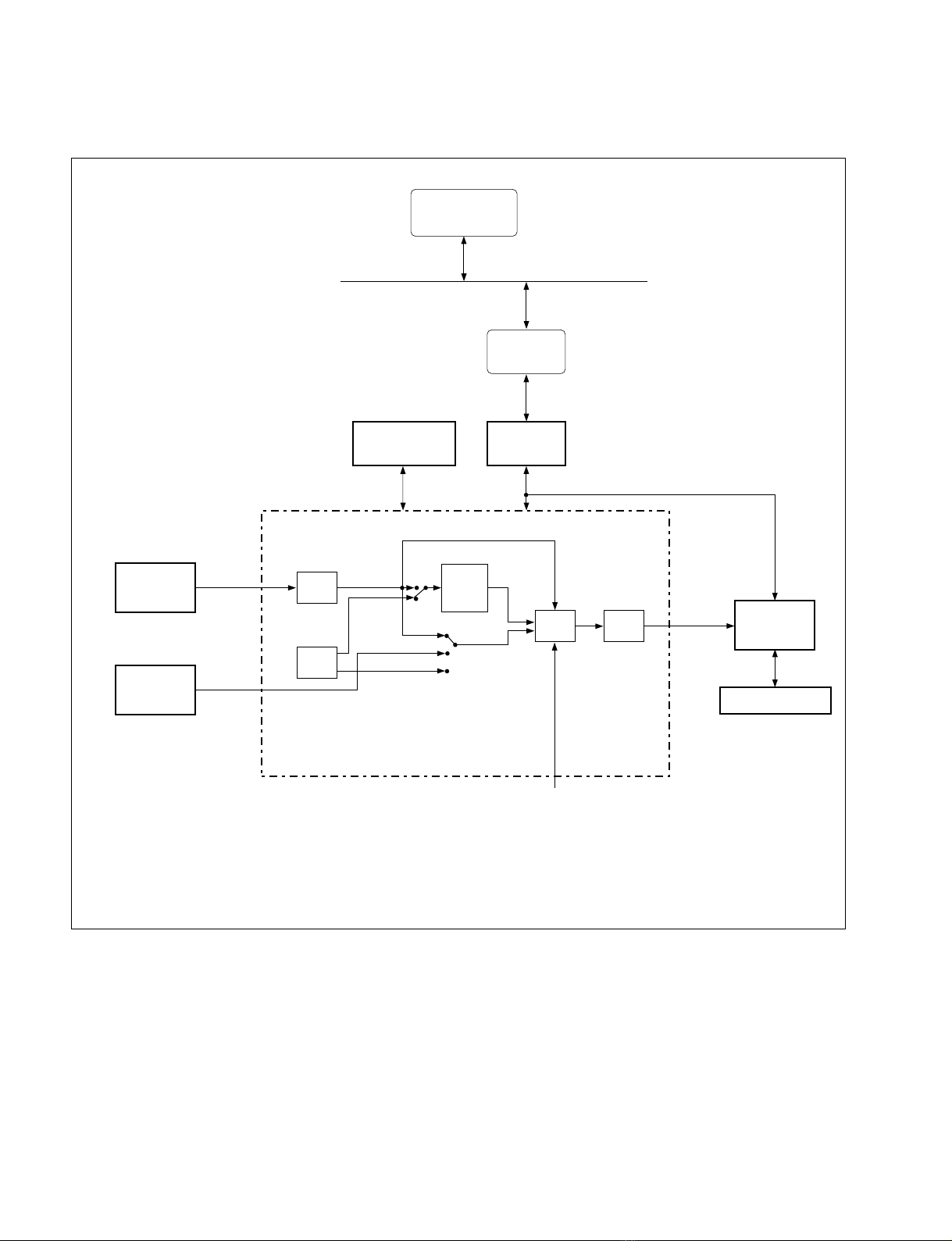
Bit Rate Reduction Encoder Board BKSI-2020 is a high quality data compression board by using SDDI
(Serial Digital Data Interface)*1) .
Converts the component video signal compressed to approximately 1/20 through 1/4 (10 through 50
Mbps) and the non-compressed audio signal to SDDI signal.
The audio signal can be transmitted long distance (600 m:when using the Belden 8281 cable) by using the
BNC connectors with a coaxial cable of the AES/EBU format. The board has a time code reader function.
A time code input signal is converted to the SDDI signal in the time code reader.
BKSI-2020 is installed in a System Interface Unit SIU-80.
The setting of the following items can be selected by the switches on this board.
• The baud rate for ISR*2) mode
• The reference input signal
• The test signal for the audio/video signal
• The audio input signal between the SDI signal and the AES/EBU signal
The settings which are performed by the software of the BKSI-2020, are set by the host control devices
which are equipped with the setting function.
The following functions can be controlled in addition to the above described functions by the external
devices using the SONY DISK PROTOCOL.
BKSI-2020 can be also controlled using the VS-BUS via SIU-80.
• Selection of the GOP*3) size and the compression rate for the video signal
• Setting of SDDI DESTINATION ADDRESS meaning a transmission address of the SDDI signal
(default value; 0)
• Setting of the non-compressed line against the insertion signal during the video vertical blanking period
• Selection of the LTC signal or the VITC signal
1-2. Configuration
• Plug-in Board (ENC-29 board) (1pc)
• Connector Panel (IO-114 board) (1pc)
• Installation Guide (1pc)
• Installation Manual (1pc)
• Model Labels (2pcs)
*1) : SDDI
The high speed data transmission system having the higher compatibility with the SDI.
The system is used to transmit the compressed video and audio signals.
*2) : ISR (Interactive Status Reporting)
Status of this board or contents of errors occurred can be centralized to be monitored and managed on the monitor screen of a
personal computer.
*3) : GOP (Group of Picture)
This is the unit of digital video signal compression.
In this system, video signal of 2 frames are compressed as 1 group.

1-2 (E) BKSI-2020
1-3. Encoder Concept
BKSI-2020
Encoder
BKSI-2050/2050P
AD Converter
BKSI-2070
SDI
Audio AD
Converter
AES/EBU
4CH
TEST
SG
VITC
SDDI
ENC
BKSI-2010
SDC
SCSI
HDD
LTC
SDDI
VIDEO
BRR
ENC
SDI
DEC
SDDI
PACK
APPLICATION
CONTROLLER
(REC/STOP etc.)
VS-BUSRS-422A
SMS
(Software)
IDC
BKSI-2040
1. Overview
SMS : Server Management System (Software)
AD Converter : Analog NTSC/PAL-4:2:2 Converter
IDC : Intelligent Device Controller
SDC : Disk Control Board
HDD : Hard Disk Drive

1-3 (E)
BKSI-2020
2. Installation of Board
Flow for installation
2-1. Plug-in Board Installation
General information for installation
•The plug-in board (ENC-29 board) is inserted into any
slot No.1 to No.8 in the front of SIU-80.
For the number of maximum boards to be installed in
SIU-80, refer to the Installation Manual supplied with
SIU-80.
•One of the model label supplied with BKSI-2020 is
attached to the shield plate to prevent the board inserting
into the incorrect slot when the board replacement and
others.
•In the board replacing, set the setting of the switches
S3000 and S3301 on a new board to the setting of the
removed board.
•In the case of the board replacement in a live SIU-80,
push the reset switch (S3001) after the board is inserted.
Procedures
1. Turn off the power of the SIU-80 and remove the front
panel and shield plate.
(Refer to the Installation Manual supplied with SIU-80.)
2. Insert the board into a slot, and then turn the board levers
in the direction of the arrow 1and connect the board
securely to the connector of the SIU-80’s mother board.
3. Install the shield plate.
Then, attach the model label on the right side of the
shield plate.
This label position should be aligned with the slot
installing the board.
4. Install the front panel.
n
If removing the board, turn the board levers in the direction
of the arrow 2, and remove the board from the slot.
2. Installation of Board
Start
Slot selection
Cable connection
Plug-in board installation : ENC-29 board
Model labels attachment
End
Connector panel installation : IO-114 board
1
2
1
212
Board lever Board lever
1Install
2Remove
SIU-80
Front panel
PSW 3X6
Shield plate
SIU-80
Model label

1-4 (E) BKSI-2020
2. Installation of Board
SIU-80
BVTT 3X6
Connector panel
Model label
3. Attach the model label supplied with the BKSI-2020 in
the chassis near the slot to install the board.
n
After the connector panel is inserted into a slot, the
model label cannot be seen.
4. Insert the connector panel to the matching slot and fix
the panel by the two screws securing the rear blank
panel.
Connector panel removal
1. Turn off the power of SIU-80 and unplug the appli-
ance from the outlet.
2. Remove the two screws securing the connector panel
and remove the connector panel.
m
•When removing the connector panel, move the panel
to the right and left slowly until the connection with
the mother board is sufficiently loose, then remove
the connector panel gently.
•Panels must be held by the plugs of the cables which
are connected to the BNC cables.
SIU-80
Rear blank panel
BVTT 3X6
2-2. Connector Panel Installation
General information for installation
•The connector panel is inserted into the same slot as the
plug-in board installed in the front of SIU-80.
•The model label supplied with the BKSI-2020 is at-
tached in the chassis to prevent the panel inserting into
the incorrect slot when the connector panel replacement
and others.
w
Do not install with turning the power on
Touching the power contact portion or the primary wind-
ing circuit may cause electric shock.
For safety reason, turn off the power and unplug the
appliance from the outlet before starting the installation.
Procedures
1. Turn off the power of SIU-80 and unplug the appli-
ance from the outlet.
2. Remove the rear blank panel. (Refer to the Installation
Manual supplied with the SIU-80.)

1-5 (E)
BKSI-2020
3. Connection
3. Connection
3-1. Location and Function of Connectors
1SDI INPUT (digital signal input) connector : BNC type
Receives the 4:2:2 component serial digital signal.
2Active through out connector : BNC type
Provides the signal with supplied to SDI INPUT connector whose waveform has been shaped (active
output).
3AUDIO INPUT (digital signal input) connector : BNC type (2 pcs)
Receives the audio signal (AES/EBU format) of channel 1 and 2, and channel 3 and 4.
4TC IN (time code signal input) connector : XLR type
Provides the time code signal.
5REMOTE connector : D-sub 9-pin type
Used for RS-422A remote control. SONY DISK PROTOCOL signal is available for this terminal.
n
This connector does not accept SONY VTR PROTOCOL signal.
6SDDI OUTPUT connector : BNC type (2 pcs)
Provides the SDDI (serial digital data interface) signal.
3-2. Connecting Connector and Cable
If any cable is connected to the connectors on the connector panel when installing or servicing, use the
connector or cable listed below or equivalent.
BKSI-2020 Connector Matching Connector/Cable
Panel Indication Connector Connector Sony Part No.
SDI INPUT BNC BNC 1-560-069-11
SDDI OUTPUT
AUDIO INPUT BELDEN 8281 cable
TC IN XLR 3-pin, Female XLR 3-pin, Male 1-508-084-11*1
REMOTE D-sub 9-pin, Female D-sub 9-pin, Male 1-560-651-00(Connector)
1-561-749-00(Shell)
RCC-5G/10G/30G Cable*2 1-751-019-81 (5G)
1-751-019-91 (10G)
1-751-020-21 (30G)
*1: CANNON XLR-3-11C or equivalent
*2: Each length of cables is 5 m, 10 m, and 30 m.
PUSH
3 5 6
BKSI-2020
1/2 3/4 REMOTE SDDI OUTPUT
12
ENCODER
AUDIO INPUT TC IN
41 2
SDI INPUT

1-6 (E) BKSI-2020
3. Connection
4. Location and Function of Switches/LEDs
3-3. Signal Input/Output
Input and output signals of connector on the connector
panel are shown below.
REMOTE:RS-422A (D-sub 9-pin, Female)
<External View>
Pin No. Signal
1 FRAME GROUND
2 TX–
3 RX+
4 GROUND
5 SPARE
6 GROUND
7 TX+
8 RX–
9 FRAME GROUND
4. Location and Function of Switches/
LEDs
4-1. ENC-29 Board
n
•Do not change the setting of the switches described as
“Factory use only”.
•( ) mark followed by the Ref No. shows the address of
switch or indicator on the board.
1D3303(A-3) :System Error indicator
When an error is detected in the system control, it
lights in red.
2D3304(A-3) :Video Error indicator
When an error is detected in the video block, it lights
in red.
3D3305(A-4) :Audio Error indicator
When an error is detected in the audio block, it lights
in red.
4D3307(A-4) :Test SG indicator
When the test signal generator operates in the board, it
lights in green.
5D3306(A-4) :Input Error indicator
When an illegal signal is detected in the SDI input
connector, it lights in red.
6D3308(A-4) :Test indicator
In the test mode (when S3000-8 is set to ON), it lights
in green.
7D3301(A-5) :Monitor indicator
While running the monitor program, it lights in red.
<Component side/A side>
5
96
1
D3303
D3304
D3305
D3307
D3306
D3308
D3301
S3301
S3000
1
2
3
4
5
6
7
8
9
0
CN1101
!-
S3001

1-7 (E)
BKSI-2020
4. Location and Function of Switches/LEDs
8S3001(A-5):Reset switch
System reset switch for hardware of the ENC-29
board.
n
Push this switch after the board replacement in a live
SIU-80.
9S3301(A-6):Mode Select switch
In the normal operating, use this switch with factory
setting as shown below.
( marks indicate the switch knob position.)
n
Push the reset switch (S3001) after the setting is
changed.
S3301-1:Mode Select
Selects the ISR mode or maintenance mode by RS-
232C communication.
When the maintenance mode is selected, the monitor
program is activated and ISR system cannot be
executed.
ON : Maintenance mode
OFF : ISR mode (Factory setting)
S3301-2, 3:Baud Rate setting
Sets the baud rate in the ISR mode or maintenance
mode by the ON and OFF combination.
S3301-2 S3301-3 Baud Rate (bps)
OFF OFF 19200 (Factory setting)
ON OFF 38400
OFF ON
-
(Not used)
ON ON
-
(Not used)
S3301-4:Program Download
Downloads the system program to the flash memory
(IC3013) on the ENC-29 board from an external
personal computer via the maintenance connector
(CN1101) on the ENC-29 board.
ON : Downloads the program
OFF : Normal operation
S3301-5 thru 8:Factory Use Only
Factory setting:OFF
0S3000(A-8):Test Mode switch
S3000-1 to S3000-7 settings are made active after the
S3000-8 is set to ON.
The setting is changed in the following procedure.
1. Set S3000-8 to ON.
2. Change the S3000-1 to S3000-7 settings.
n
If returns to the factory setting,
1. Set S3000-8 to OFF.
2. Push the reset switch S3001.
In the normal operating, use this switch with factory
setting as shown below.
( marks indicate the switch knob position.)
S3000-1:Reference select
Selects the reference signal to which SDDI output
locks.
ON : SIU-80 reference (Factory setting)
OFF : SDI input
S3000-2:Video Test Signal select
Selects the signal for the video test.
ON : Test signal (100% color-bar signal)
OFF : Normal operation
S3000-3, 4:Audio Test Signal select
Selects the signal for the audio test by ON and OFF
combination.
S3000-3 S3000-4 Audio Test Signal
OFF OFF Normal mode by SDI input signal
(Factory setting)
OFF ON Normal mode by AES/EBU input signal
ON OFF Test signal (1 kHz sine wave)
ON ON Test signal (1 kHz sine wave)
S3000-5:Prefilter Bypass ON/OFF
(Added: S/N 11001 and higher)
Selects whether the prefilter is operated or not.
When this switch is set to OFF, the prefilter is
operated.
ON : Bypass ON (The prefilter is not operated.)
OFF : Bypass OFF
(The prefilter is operated; Factory setting)
S3000-6:Factory Use Only
Factory setting:OFF (Always)
ON
1 2 3 4 5 6 7 8
S3301
ON
1 2 3 4 5 6 7 8
S3000

1-8 (E) BKSI-2020
4. Location and Function of Switches/LEDs
S3000-7:GOP Color Frame Lock Mode select
(Added: S/N 11001 and higher)
Selects whether the recording GOP is locked to the
color frame of the SDI signal or not.
ON : GOP color frame lock mode
OFF : Free-run mode (Factory setting)
S3000-8:Local Setting ON/OFF
Selects whether the S3000-1 to S3000-7 setting is
remote-controlled from the external controllers or
whether the BKSI-2020 operates according to
S3000-1 to S3000-7 setting. If S3000-8 is set to ON,
the S3000-1 to S3000-7 setting cannot be remote-
controlled from the external controllers.
ON : S3000-1 to S3000-7 setting is available
OFF : Factory setting is available
(normal operation; S3000-1 to S3000-7
setting is not available)
n
For the S3000-1 to S3000-7 setting to have effect,
S3000-8 is held in the ON position.
!- CN1101(A-11):Maintenance connector
This connector is used for the monitor program at the
maintenance mode. A personal computer is connected
to this connector. (For details, refer to Maintenance
Manual.)
4-2. IO-114 Board
n
( ) mark followed by the Ref No. shows the address of
switch or indicator on the board.
1RV100(C-11):Free-run Frequency Adjustment
volume
For the details of the adjustment, refer to Maintenance
Manual.
2RV300(C-3):Free-run Frequency Adjustment
volume
For the details of the adjustment, refer to Maintenance
Manual.
4-3. Selection of Audio Input Signal
The SDI input signal or the AES/EBU input signal can be
selected as the audio input signal of BKSI-2020.
The audio input signal is selected by ON and OFF combi-
nation of switch S3000-3 and -4.
1. Set S3000-8 to ON.
2. Set S3000-3 and -4. (Refer to the table below.)
S3000-3 S3000-4 Audio Input Signal
OFF OFF SDI input signal (Factory setting)
OFF ON AES/EBU input signal
<Component side/A side>
1
RV100 1
RV300

1-9 (E)
BKSI-2020
5. Specifications
5. Specifications
General
Operating temperature 5 °C to 40 °C (41 °F to 104 °F)
Storage temperature –20 °C to +60 °C (–4 °F to +140 °F)
Operating humidity 10 to 90 % (no condensation)
Dimensions Plug-in board : 284 X384 mm (H/W)
Connector panel : 301 X95 mm (H/W)
Mass Plug-in board : 1.0 kg (2 lb 4 oz)
Connector panel : 0.4 kg (15 oz)
Power requirements +5 V dc : 5.3 A
–5.2 V dc: 1.3 A
(supplied from SIU-80)
Power consumption 33 W
Input/Output
Digital input SDI INPUT connector (BNC type):1 pc (with active through-output)
75 Ω
4:2:2 component serial digital interface (SDI) signal input
SMPTE 259M, 270 MHz
ITU 656
AUDIO INPUT connector (BNC type):2 pcs
75 Ω
Digital audio signal input (CH-1/2 and CH-3/4)
AES/EBU format
TC IN connector (XLR 3-pin type, female):1 pc
Time code signal input
0.5 thru 18.0 Vp-p, 10 kΩ, balanced
Digital output SDDI OUTPUT connector (BNC type):2 pcs
75 Ω
Serial digital data interface (SDDI) signal output
SDDI format compressed signal
Others REMOTE connector (D-sub 9-pin type, female):1 pc
Based upon RS-422A

1-10 (E) BKSI-2020
5. Specifications
Video characteristics
Sampling frequency Y signal : 13.50 MHz
B-Y, R-Y signal : 6.75 MHz
Quantization 8 bits/sample
Encoding sampling Y signal : 720 sample
B-Y, R-Y signal : 360 sample
Encoding line 525/59.94 512 line
625/60 608 line
Bit Rate MAX:50 Mbps
Compression Format Operation compensation (MC) + discrete cosine convert (DCT)
Audio characteristics
Sampling frequency 48 kHz (synchronized to video)
Quantization 16 bits/sample
Input channel Non-compressed 4 channels
Design and specifications are subject to change without notice.

1-11 (E)
BKSI-2020
6. ISR
6. ISR
6-1. Overview
The BKSI-2020 corresponds to an ISR (Interactive Status Reporting) function.
Using this function, the status of the BKSI-2020 or the contents of a generated error can be intensively
monitored and managed on the monitor screen of a personal computer. The data displayed on the monitor
screen can be stored or printed as a file.
The major functions of the BKSI-2020 are as follows.
Monitor functions
n
•If a message is displayed, check whether the normal signals are input.
•“*”in the message shows the channel No. (1, 2, 3, or 4).
• Error message
[Video Block error] mark; Added (S/N 11001 and higher)
Message Description
VITC READER INPUT PARITY ERROR The parity error is detected in the input signal to the VITC
reader
PREFILTER INPUT PARITY ERROR The parity error is detected in the input signal to the prefilter
VIDEO BRR ENC INPUT PARITY ERROR The parity error is detected in the input signal to the BRR
encoder
VIDEO BRR MEP TO ENC INTERFACE The parity error is detected during data transmission from
PARITY ERROR BRR MEP to the BRR encoder
VIDEO BRR ENC SDRAM R/W ERROR The read/write error is detected in SDRAM connected to the
BRR encoder
VIDEO BRR ENC TO MEP INTERFACE The parity error is detected during data transmission from
PARITY ERROR the BRR encoder to BRR MEP
VIDEO BRR MEP SDRAM R/W ERROR The read/write error is detected in SDRAM connected to BRR
MEP
SDDI VIDEO PACKING INPUT PARITY ERROR The parity error is detected in the input signal to the packing
controller
SDDI VIDEO PACKING MEMORY READ The parity error is detected in the input signal from the memory
PARITY ERROR to the packing controller
[Audio Block error]
Message Description
SDDI AUDIO RATE CONVERSION MEMORY READ The parity error is detected in the input signal from the
PARITY ERROR memory to the packing controller
SDDI PACKING IC AUDIO CH*INPUT The parity error is detected in the channel No.*input signal
PARITY ERROR to the packing controller
[Video/Audio Block error]
Message Description
SDDI IC INPUT PARITY ERROR The parity error is detected in the input signal to the SDDI
encoder

1-12 (E) BKSI-2020
6. ISR
•Warning message
[Video/Audio Block warning]
Message Description
NO SDI INPUT Indicates that no signal is input or the input signal is not judged to be
contained in SDI INPUT connector
EDH FULL FIELD CRC ERROR The error is detected in the EDH full field CRC check when SDI signal
with EDH is input in SDI INPUT connector
[Audio Block warning]
Message Description
SDI AUDIO CH*INPUT DATA ERROR The error is detected in channel No.*of SDI audio input signal when
SDI AUDIO input has been selected
[Other warning]
Message Description
TEST MODE ACTIVE BY DIP SWITCH The test mode is active (S3000-8 is set to ON)
•Operation status
Message Status Display Description
VIDEO INPUT SDI SIGNAL Indicates the setting of the input video signal
100% COLOR-BAR TEST SIGNAL
75% COLOR-BAR TEST SIGNAL
MULTI BURST TEST SIGNAL
BLACK TEST SIGNAL
AUDIO CH*INPUT SDI SIGNAL Indicates the setting of the input audio signal
AES SIGNAL
1 kHz TEST SIGNAL
SILENCE TEST SIGNAL
REF LOCK MODE INPUT Indicates the setting of the REFERENCE signal of
REF the encoder
VIDEO GOP LENGTH 1 FRAME Indicates the size of the GOP of the video signal
2 FRAME
VIDEO BRR BIT RATE [•••] Mbps Indicates the setting of the bit rate of the video
signal

1-13 (E)
BKSI-2020
RS-232C Cross cable
SIU-80
Management functions
•Model name and slot number
•ROM Version
Indicating item Description
Manufacturer Displayed as SONY
Model Displays the model name (BKSI-2020)
Device ID Can give an arbitrary name to this board and register it
VM sub-address Displays the address number (slot number +1) of SIU-80 in which this board is inserted
Destination Displays the destination (NONE)
ROM Displays the information of the ROM mounted on the board
(Board name, ROM name, version, board address, and blank ROM name)
6-2. ISR Use Environment
The ISR function is controlled by Sony application program software. For the program software, use,
installation, and operation of a personal computer in which this program software can be used, consult
with your local sony’s sales/service office.
The preparation below is required when managing the BKSI-2020 by ISR.
1. Connect a personal computer to the RS-232C connector (D-sub 25-pin) of the SIU-80 which is
installed the BKSI-2020 using a RS-232C cross cable.
2. Install the ISR application program software to the computer.
6. ISR
Personal computer


The material contained in this manual consists of
information that is the property of Sony Corporation and
is intended solely for use by the purchasers of the
equipment described in this manual.
Sony Corporation expressly prohibits the duplication of
any portion of this manual or the use thereof for any
purpose other than the operation or maintenance of the
equipment described in this manual without the express
written permission of Sony Corporation.
Le matériel contenu dans ce manuel consiste en
informations qui sont la propriété de Sony Corporation et
sont destinées exclusivement à l’usage des acquéreurs
de l’équipement décrit dans ce manuel.
Sony Corporation interdit formellement la copie de
quelque partie que ce soit de ce manuel ou son emploi
pour tout autre but que des opérations ou entretiens de
l’équipement à moins d’une permission écrite de Sony
Corporation.
Das in dieser Anleitung enthaltene Material besteht aus
Informationen, die Eigentum der Sony Corporation sind,
und ausschließlich zum Gebrauch durch den Käufer der
in dieser Anleitung beschriebenen Ausrüstung bestimmt
sind.
Die Sony Corporation untersagt ausdrücklich die
Vervielfältigung jeglicher Teile dieser Anleitung oder den
Gebrauch derselben für irgendeinen anderen Zweck als
die Bedienung oder Wartung der in dieser Anleitung
beschriebenen Ausrüstung ohne ausdrückliche
schriftliche Erlaubnis der Sony Corporation.

Printed in Japan
Sony Corporation 1997. 3 16
Broadcast Products Company ©1996
Published by Broadcast Products Company
BKSI-2020 (SY) J, E
3-190-291-03
Table of contents
Other Sony Media Converter manuals

Sony
Sony DSC-1024HD User manual

Sony
Sony Ipela SNT-EX104 User manual

Sony
Sony BKMA-7030 User manual

Sony
Sony SQD-2020 Setup guide

Sony
Sony BKMW-104 User manual

Sony
Sony BKSM-T103 User manual

Sony
Sony PCWA-DE80 Read This First Instruction sheet

Sony
Sony NXLK-IP50Y User manual

Sony
Sony GIGAJUKE NAS-C5E User manual

Sony
Sony VGF-WA1 User manual

Sony
Sony HKSP-525 User manual

Sony
Sony MKS-6550 User manual

Sony
Sony HKSP-313 User manual

Sony
Sony NSBK-A16H User manual

Sony
Sony MVE-8000 User manual

Sony
Sony MEU-WX1 User manual

Sony
Sony CarrierGate PCWA-DE50 Instruction sheet

Sony
Sony BDX-E1000 User manual

Sony
Sony HKSP-1125 User manual

Sony
Sony XV-T33 - Video Sketch Titler User manual