Artos 45-700 User manual

0
Machine Model 45-700 Wire Prepper II Owners Manual
PN 6-119891 Rev. 1.00 Date August 18, 2015
Artos Engineering Company
21605 GatewayCt.
Brookfield, WI 53045
Phone 262 252-4545 Fax 262 252-4544
www.artosnet.com

1
TABLEOFCONTENTS
CustomerSafetyNotice..................................................................................................................2
LimitsofUse....................................................................................................................................2
Introduction....................................................................................................................................2
Unpacking.......................................................................................................................................2
OperatorControlFeatures..............................................................................................................3
ON‐OFFSwitch............................................................................................................................3
ControlButtons...........................................................................................................................3
StandardFeatures...........................................................................................................................3
Set‐up..............................................................................................................................................4
PuttingtheMachinetoWork.........................................................................................................4
OperatingInstructions....................................................................................................................5
ChangingProgramSettings.............................................................................................................6
WireDriveSpeed:.......................................................................................................................6
StoringWireBatches:.................................................................................................................6
RecallWireBatches:...................................................................................................................6
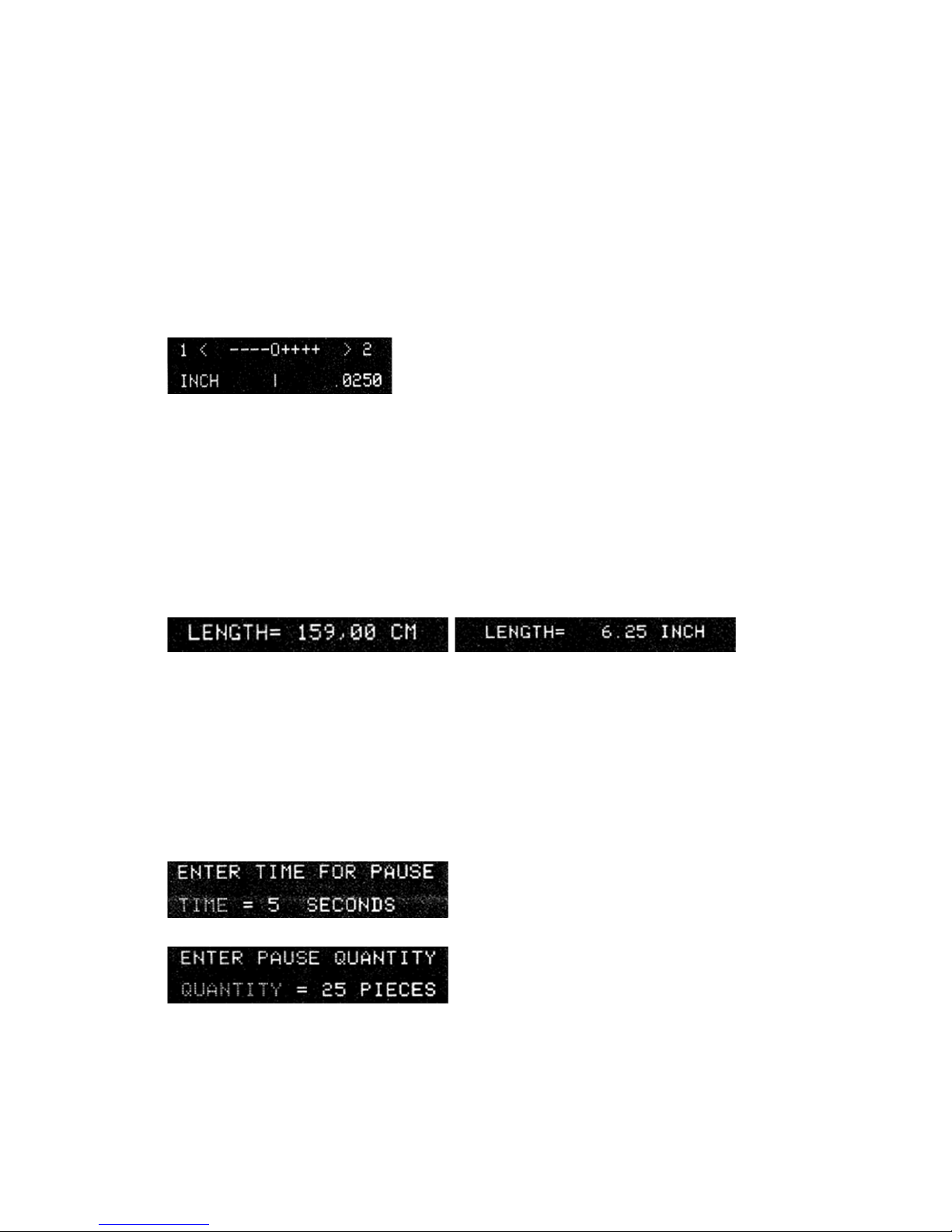
WireLengthCalibration:.............................................................................................................6
ChangingMode:..........................................................................................................................7
ActivatePauseMode:.................................................................................................................7
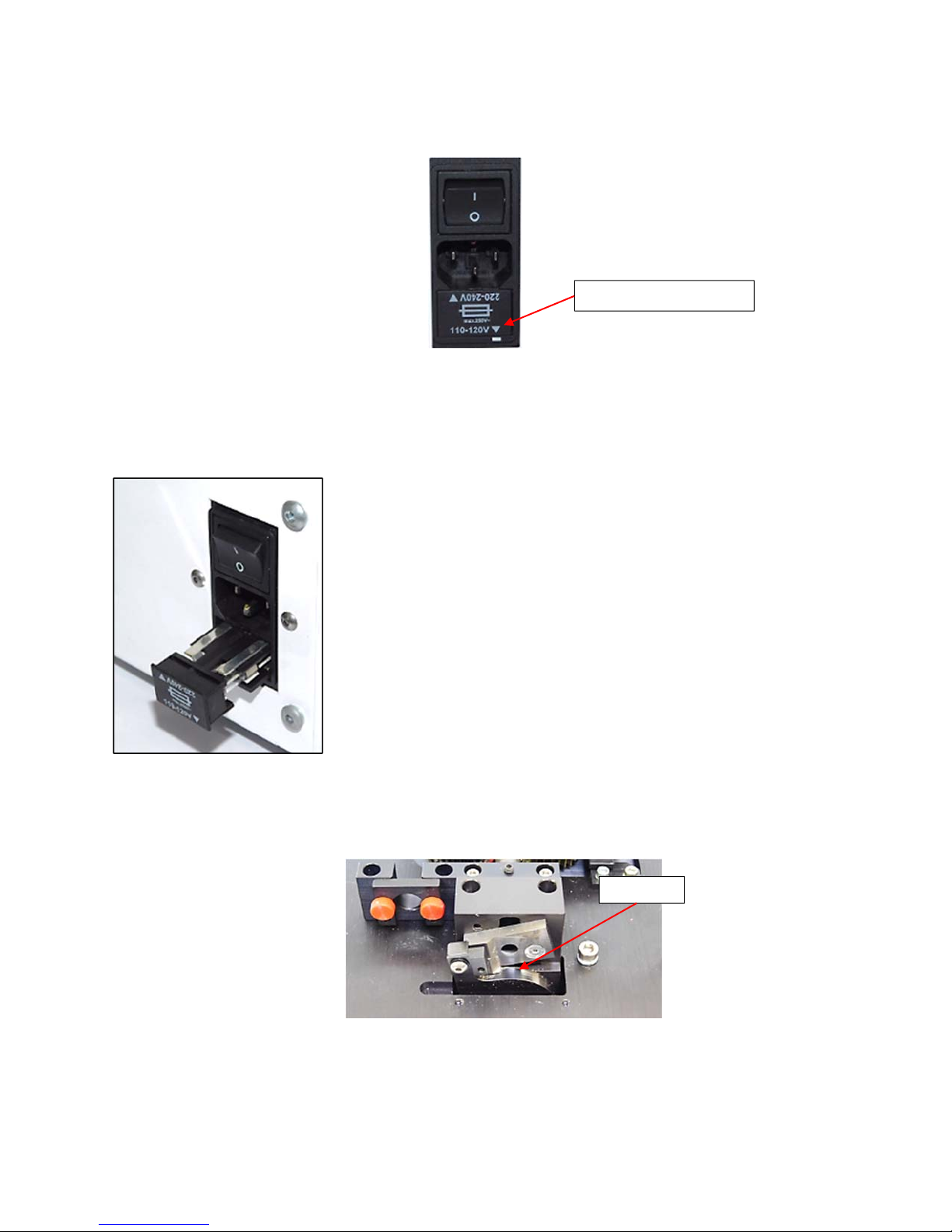
VoltageSelection............................................................................................................................7
FuseReplacement...........................................................................................................................8
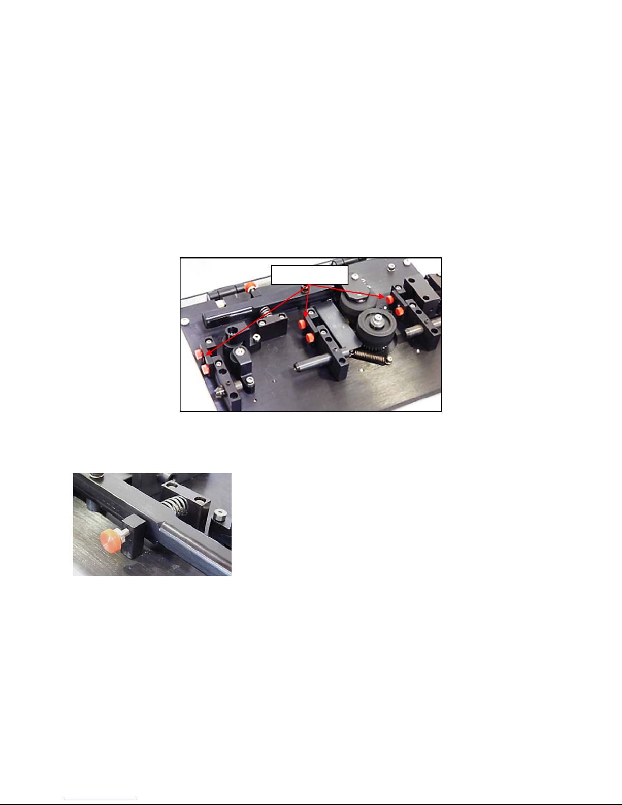
Maintenance...................................................................................................................................8
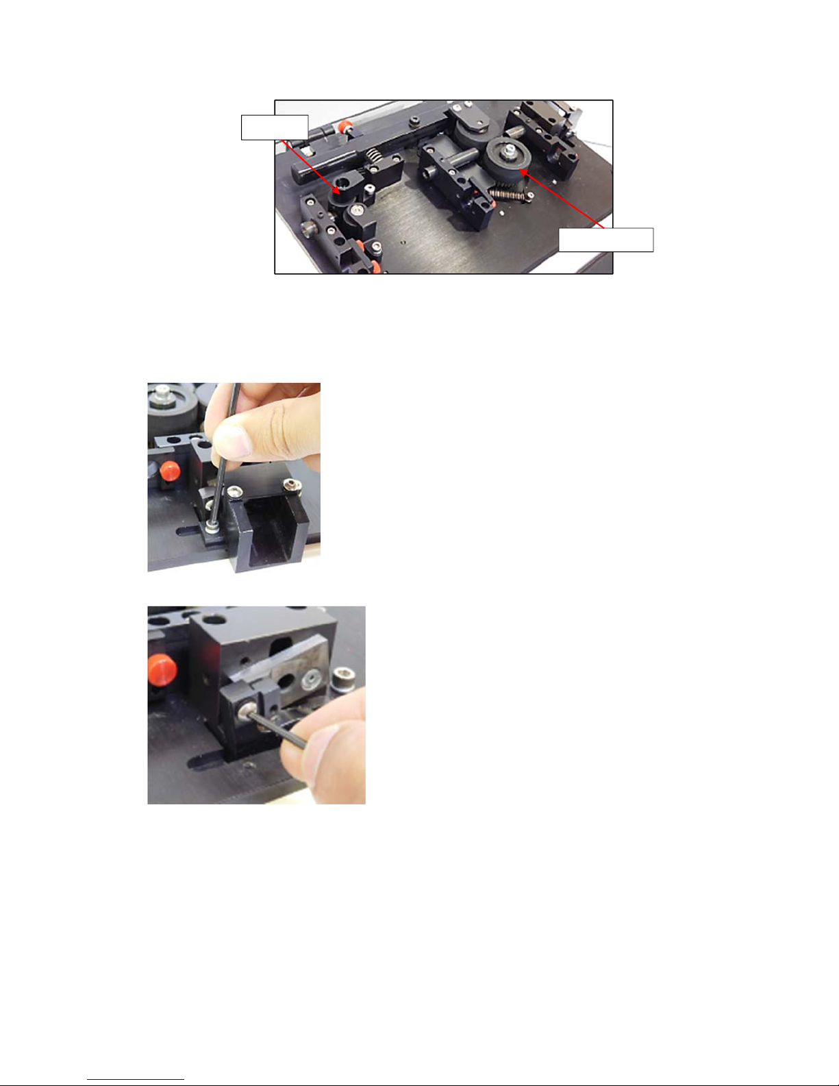
BladeReplacement.........................................................................................................................9
EncoderDisassembly....................................................................................................................10
EncoderAssembly.........................................................................................................................13
DriveWheelReplacement............................................................................................................14
TroubleShooting...........................................................................................................................16
“WireAlarm”Sounds................................................................................................................16
WireLengthNotAccurate........................................................................................................16
DisplayReads“CalculatingCalRegisters”................................................................................16
DisplayReads“CutterMalfunction,MachineWillNotCut”....................................................17
MachineWillNotFunction,AllSwitchesDoNotWork............................................................17
CuttersCyclesContinuously.....................................................................................................17
DriveWheelOperationisRough..............................................................................................17
CuttersDoNotCutMaterialCleanly........................................................................................18
WireandTubingCutsareNotSquare......................................................................................18
TubingCrushedbyRollers........................................................................................................18
Accessories....................................................................................................................................19

2
CustomerSafetyNotice
Useofthismachineforpurposesotherthanthosestatedinthismanualmayresultindamage
tothemachineorpersonalinjury.
Useofthismachineforpurposesotherthanthosestatedinthismanualmayresultindamage
tothemachineorpersonalinjury.
WARNING
Donotmanuallydisableguardswitchesorsafetycovers.Personalinjurycanresult.
Donotperformanymaintenanceonthemachineunlesstheelectricalsupplytothemachineis
disconnected.
Donotattempttoreplacethebladesorthefeedrollersunlesstheelectricpoweris
disconnectedfromthemachine.
Donotoperatemachinewithoutwearingpropereyeprotection
Donotwearlooseclothingorjewelrythatmightgetcaughtintheoperatingpartsofthe
machine
Donotoperatemachineinadamporwetlocation
Donotoperateifliquidisspilledonorinthemachine
Donotoperatemachineonanungroundedelectricalsystem
Donotalter,modify,ormisusethemachine
Donotoperatemachineunlessallinstructionsarereadandunderstood
Donotoperatemachineinagaseousorhazardousenvironment.
LimitsofUse
TheWirePrepper®SystemIIisintendedforuseinadryindoorworkingenvironment.The
machinecannotbeexposedtoliquidsprayormist,damagewillresult.Circuitsshouldneverbe
removedortamperedwithorinjurymayresult.
Introduction
TheWirePrepper®SystemIIisequippedtocut10‐30AWGwireandothermaterialsincluding
¾”ribboncableand½”diameterheatshrinktubing.TheWirePrepper®SystemIIisfactoryset
for120V.operation.For220V.operationconsultthesectionon“VoltageSelection”inthis
manual.
Unpacking
YourWirePrepper®SystemIIhasbeenshippedinstaticdissipativepackaging.Observe
precautionsforhandlingelectrostaticsensitivedevices.Savethisboxandpackingmaterialfor
futuretransportation.

3
OperatorControlFeatures
ON‐OFFSwitch‐Turnsmainpoweronandoff.Locatedonthebackofthecase.Contains
machinefuses.
ControlButtons
Run—startsmachinecycletomeasureandcut.
Stop—Stopsmachinecycle.
Length—Allowslengthdatatobeenteredfrom0.06”‐9,999.99”
Quantity—allowsquantitytobeenteredfrom1‐9,999pieces.
Jog—Activateswirefeedmotor.
Cut—Activateswirecutter.
Program—Allowsaccesstowiredrivespeed,wirebatches,lengthcalibration,mode(inchesor
centimeters),pausetimebetweenbatches,anddemoprogram.
Clear—Usedtocleardatafromdisplay.
Enter—Usedtoenterdataonceithasbeendisplayed
Keyboard—0thru9keyboardwithdecimalpointforenteringnumericaldata,tosetlengthand
quantity.
StandardFeatures
RetainedMemory—Allmachineprogramsettingsareelectronicallystoredinmemory.Preset
lengthandquantityremainingondisplaywillbesavedincaseofpowerfailure.
WireAlarm—Anaudioandvisualalarmtoindicatethatthewireisnotfeeding.PressSTOPto
turnoffalarm.Loadnewwireorclearjam.PressJOGandCUTtocutexcesswire.PressRUNto
restartmachine.
WireLengthCalibration—Aprogramwhichallowstheoperatortoadjustthecutlengthfor
greateraccuracy.
Mode—(UnitofMeasure)AprogramwhichallowstheWirePrepper®tomeasureininchesor
centimeters.

4
PausingBatching—AprogramwhichwillpausetheWirePrepper®forupto9secondsbetween
batchesofwire.(i.e.Themachinecanbesettomeasureandcut4,000wires,andbe
programmedtopausefor5secondsafterevery50wires.Thispermitssmallbundlesforeasier
handling).
Set‐up
TheWirePrepper®SystemIIhasbeenset‐upatthefactorytocutplastictubing,heatshrink,
andstranded‐copperwire.
Tocutlargermaterials,positiontheslottedguidesinplaceofthefeedtubes.Thisiseasilydone
byremoving2screws(use
7
/
64
”hexwrench)holdingeachguidesupportblockandrotatingthe
block180°.
Whencuttingroundtubing,aslightflatteningofthetubingmayoccur.Tominimizethis,a
releaseleverscrewisprovidedtolimittheclosingofthedrivewheels.Turnclockwisetolessen
thepressureandtestforproperfeed.
TheWirePrepper®SystemIIcanalsocutSJOcordandmulti‐conductorroundcableupto
3
/
8
”
dia.Forthisset‐upinstalloptional0.338I.D.feedtubesset(LB1448)and0.375dia.fixedblade
(LB1481).SeebladereplacementPg.8.
PuttingtheMachinetoWork
‐PlugthecordintoON‐OFFswitchpowermodule.
SlottedGuides

5
‐WiththemachineturnedOFF,raisethecover.
‐Inserttubinginthefirstguidetubepasttheencoderrollersuntilthetubingistouching
thefeedrollers.Whilepushingthetubinglightlyagainstthefeedrollers,rotatethefeed
rollersbyhandtofeedthetubingthroughthemachineandoutthedischargechute.
‐ClosecoverandturnthemachineON.(Prepperwillnotrunwiththecoveropen).
‐PressJOGtofeedtubing.
‐PressCUTtocutoffexcesstubing.
‐TheWirePrepperisnowreadytomeasureandcuttubing.
OperatingInstructions
EnteringCutLength
‐PressLENGTH
‐Enterdesiredlength
‐PressENTER
EnteringQuantity
‐PressQUANTITY
‐Enterdesiredquantity
‐PressENTER

6
ChangingProgramSettings
WireDriveSpeed:
10wiredrivespeedareavailabletovarythefeedspeedofthewirethroughthemachine.
Varyingthewirefeedspeedwillenabletheoperatortooptimizethemachineperformance.
‐PressPRGM(Program).
‐Press1(onkeyboard)
‐Press1forslower,2forfaster
‐PressENTER.
StoringWireBatches:
Awirebatchconsistsoflength,quantity,andothermachinesettingsforfrequentlyrepeated
productionjobs.Upto99batchescanbeprogrammedbytheoperatorandstoredinthe
machine’selectronicmemory.
‐Enterdesiredlengthandquantityontothedisplaypanel.
‐PressPRGM.
‐Press2.
‐EnterBatch#.
‐PressENTER.
‐Press2tostore.
RecallWireBatches:
‐PressPRGM.
‐Press2.
‐Enterbatch#toberecalled.
‐PressENTER.
‐Press1torecall.
‐Todeleteprogram,overwritewithanotherprogram.
WireLengthCalibration:
Calibration(ofwirelength)enablestheoperatortoadjustthecutlengthforgreateraccuracy.
Incrementalchangesinthecalibrationsettingwillvarywithwirelength.Forexample,fora10”

7
wire,eachincrementalchangeincalibrationwillresultinapproximately0.040”changeinwire
length.Fora100”wire,eachincrementalchangeincalibrationwillresultinapproximately
0.40”changeinwirelength.
‐PressPRGM.
‐Press3fornext.
‐Press2formode.
‐Press1forcalibration.
‐Press1forShorter,2forlonger,or3toreset.
‐PressENTER.
NOTE:Samplewireshouldbetakenbeforeandafteracalibrationchangeismade.Incrementalchanges
willbegreaterforlongerwires.
ChangingMode:
Mode(unitofmeasure)allowsthemachinetomeasureininchesorcentimeters.
‐PressPRGM.
‐Press3fornext.
‐Press2formode.
‐Press1forMetric(cm)or2forEnglish(in).
ActivatePauseMode:
‐PressPRGM.
‐Press3fornext.
‐Press3againfornext.
‐Press1forPAUSE.
‐Press1againtoenterpausemode.
‐Enterpausetime(0‐9seconds)andpressENTER.
‐EnterpausequantityandpressENTER.
NOTE:TodisplaypausedatapressENTERkey.
VoltageSelection
Tochangeselectedvoltage:removethefusecartridgeusingasmallbladescrewdriverorsimilar
tool;selectthedesiredvoltagebymatchingthearrowonthefusecartridgetothearrow

8
locatedonthefrontoftheunit(lowerrightcorner);replacethefusecartridgemakingsurethe
voltageselectionarrowalignswiththearrowlocatedinthefrontoftheunit.
FuseReplacement
Removethefusecartridgeusingasmallbladescrewdriverorsimilartool.Replacetwo3AMP
Slo‐Blofuses,andinsertthefusecartridgebackintotheunit;makingcertainthePROPER
VOLTAGESELECTIONARROWalignswiththenarrowlocatedonthefrontoftheunit.
Maintenance
‐
Periodicoilingofthebladearmisrequired.Twodropsofoilwherethebladearmpivots.
Thefrequencywilldependonusage.
‐
Periodiccleaningoftheencoderanddriverollerswhenbuild‐upappearswillhelp
assureaccuratemachineoperation.
VoltageSelectionArrow
O
ILHERE

9
BladeReplacement
1. Unplugtheunit.
2.
Removedischargechute.
3.
Removebladeretainingclip.
4.
Liftoutmovableblade.
5.
Removethescrewsholdingthefixedblade.
Driv
e
R
o
ll
e
r
s
Encoder

10
NOTE:Removescrewsfrombladeblock(use
7
/
64
”hexwrench)androtatetheblockafewdegreesto
accesslowerleftbladescrew.
6. RemovethefixedBlade.
NOTE:Thisbladecanberotated180°touseothercuttingedge.
EncoderDisassembly
1. Removethetopplateassemblyandplaceitupsidedownontheworkbench.
2. Useaflatbladescrewdrivertoturnthelocktothepositionwithonedot.Thiswill
exposeaholeinthesidewhereahexwrenchcanbeinserted.

11
3. Inserta0.034”hexwrenchintothebodyoftheencoderinsuringthatitisproperly
seatedintothecodewheelhubsetscrew.Youwillhavetoturnencoderrollertofind
thisposition.
4. Loosenthesetscrewbyturningcounterclockwise.
5. Removetheencoderformtheencoderbasebyinsertingasmallbladescrewdriverat
thesnaplocationsandtwistingslightly.
Hole

12
6. Gentlyremovetheplasticcodewheelretainer.
7. Removethehexwrench.
8. Removethecodewheel,cleanwithcontactcleaner.
9. Installthecodewheelandplasticcodewheelretainerbackintotheencoderhousing.
10. Insertthe0.034”hexwrenchtoengagethecodewheelhubsetscrew.Encoderisnow
readyforassemblytotopplate.
Snaplocation
Sna
p
location

13
EncoderAssembly
1. Snaptheencoderbodyontothetopplatelockingall4snaps.
2. Withthe0.034”hexwrenchproperlyseatedintothecodewheelhubsetscrewapplya
downwardforceontheendofthehexwrench.Thissetsthecodewheelgapbyleveling
thecodewheelhubtoitsupperposition.
3. Whilecontinuingtoapplyadownwardforce,rotatethehexwrenchintheclockwise
directionuntilthehubsetscrewistightagainstthewheelshaft.
4. Removethehexwrenchbypullingitstraightoutoftheencoderbody.
5. Usethecenterscrewdriverslot,oreitherofthetwosideslots,torotatetheencodercap
dotclockwiseformtheonedotpositiontothetwodotposition.

14
6. Recheckencoderrollersforfreemovement.
7. Separatewheelsbyhandandrotatewheel.
8. Theencoderisreadyforuse.
DriveWheelReplacement
1. Removethe3screwsfromthespringpressureondrivewheelsandtheretainingblock.
2. Removethescrew(#10‐32)(use
5
/
32
“hexwrench)holdingdrivewheeltomotorshaft
andremovedrivewheel/gearassembly.
Retainin
g
Block

15
3. Removethe2(#8‐32)buttonheadscrewsthenremovethewheeltopplateandspac
4. Removedrivewheel/gearassembly.
5. Removegearandspacerfromeachdrivewheel.
6. Installgearandspacerontonewdrivewheel,usingthefixturepin(LB1429)providewith
machine.Tightenscrewssecurely.

16
NOTEFixturepinisnecessarytoassurealignment
7. Reassembledrivewheelsandsprings.
TroubleShooting
“WireAlarm”Sounds
Checkforwirejamsatmachineorde‐reeler.
Checkwirestraighteneradjustment(wirestraightenerisanoptionalaccessory).
Pressureonwiremaybetoohigh.
Checkencoderwheelfromfreerotation.Pushspringloadedwheelawayfromencoder
wheel,thenspinencoderwheel.Itismountedonballbearingsandshouldrotatefreely.
Ifrestrictionisfelt,seeEncoderAssembly/Disassemblyprocedure.
Makesurethatthefirstwirefeedtubeisnotrubbingagainsttheencoderwheels.
WireLengthNotAccurate
Checkwirelengthcalibration.Thenumberinthelowerrightcornerofthecalibration
viewingscreenshouldbecloseto0.025.Ifnecessary,press3toresetwirecalibration
(shouldresetto0.025).
Checkde‐reelerforsmoothoperation.Aneasycheckistohandfeedthewiretothe
machinesothatthereisnorestriction.Ifthecutwiresbecomeaccurate,thenthe
problemisinthede‐reeling.
Checkencoderrollersforfreemovement,orforeignmatter.
Checkencodercodewheelforforeignmaterialinwindows.Todothis,itisnecessaryto
disassembletheencoderfromthetopplate.Referto“EncoderDisassembly”inthis
manual.
DisplayReads“CalculatingCalRegisters”
Turnmachineoff.Whilepressingandholdingthedecimalpointbutton,turnmachine
on.Thiswillresetthemachineelectronics.

17
DisplayReads“CutterMalfunction,MachineWillNotCut”
Removedischargechute,checkforobstructionatcuttingblade.
Removetopplateassemblyfromcase,rotatecuttermotorarm,andcheckforjammed
cuttermechanism.
Checkcuttermotorelectricalconnections.
MachineWillNotFunction,AllSwitchesDoNotWork
Turnthemachineoffandthenbackontoresetthemachineelectronics.
CuttersCyclesContinuously
Checkcutterhomesensorswitchlocatedunderthetopplate.Whenthecutterarmisin
thehomeposition,thesteelvaneshouldbeinsidetheswitchslot.Adjustthesteelvane
sothatthecuttingbladeclearsthecuttingholewheninthehomeposition.
DriveWheelOperationisRough
Checkfordebriscaughtindrivegears.

18
Removecentertubingguideassembly.
Afterremovingdebris,replaceallparts.
CuttersDoNotCutMaterialCleanly
Checkcuttingbladesforsharpness.
NOTE:Fixedbladecanberotated180°touseothercuttingedge.SeeBladeInstallation.
Increasepressureatcuttingbladesbyturningbladeclipsetscrewclockwise
1
/
8
”to
1
/
4
”
turn(use0.05hexwrench).Makeasamplecuttoassurecompletecleancutting.
WireandTubingCutsareNotSquare
Selectfeedtubessizedclosertowirediameter(see“Accessories”section).
Useoptionalroundholefixedblade(see“Accessories”section).
TubingCrushedbyRollers
Adjustreleasedleverscrewtolimittheclosingofthedriverollers.Turnclockwiseto
lessenpressure.
NOTE:Ifdriverollersdonotclosesufficientlyontothetubingthe“WireAlarm”maysound.
Optionallightforcespringsareavailableforencoderanddrivewheels.SeeReplacement
PartsLostforpartnumers.

19
Accessories
Supportset
1
/
4
”O.D.FeedTubes(setof3)
7
/
16
”O.D.FeedTubes(setof3)
ReplacementDriveWheels(set)
DescriptionPart#
FeedTubeSupportSet
for¼”O.D.(setof3)
LB‐1438
DescriptionPart#
0.180I.D.LB‐1439
0.152I.D.LB‐1440
0.120I.D.LB‐1441
0.084I.D.LB‐1442
0.060I.D.LB‐1443
DescriptionPart#
0.265I.D.LB‐1444
0.281I.D.LB‐1445
0.312I.D.LB‐1446
0.344I.D.LB‐1447
0.388I.D.LB‐1448
DescriptionPart#
UrethaneDrive
Wheels
45‐721
SteelKnurledDrive
Wheels
45‐722
Table of contents
Other Artos Cutter manuals