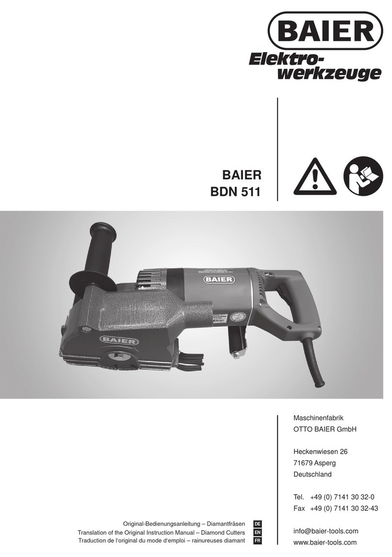
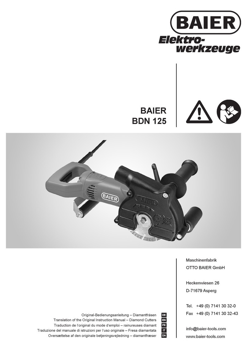
Baier BDN 452 User manual

Maschinenfabrik
OTTO BAIER GmbH
Heckenwiesen 26
D-71679 Asperg
Tel. +49 (0) 7141 30 32-0
Fax +49 (0) 7141 30 32-43
www.baier-tools.com
BAIER
BDN 452, BDN 453, BDN 454, BDN 455,
BDN 463/4, BDN 464/4, BDN 466/6
Translation of the Original Instruction Manual – Diamond Cutters EN
Tłumaczenie oryginalnej instrukcji obsługi – bruzdownice diamentowe PL

| 2 |
EN Translation of the Original Instruction Manual – Diamond Cutters 7 – 24
PL Tłumaczenie oryginalnej instrukcji obsługi – bruzdownice diamentowe 25 – 42

| 3 |
1
3 BDN 452 /BDN 453/BDN 454 /BDN 455
2

| 4 |
5 BDN 464/ 4
*
5a = 5 x 3 mm 5b = 3 mm 5c = 3 x 3 mm
6 BDN 466/ 6
*
5a = 3 mm 5b = 2 mm 5c = 3 mm 5d = 2 x 2 mm
4 BDN 463/ 4
*
5a = 3 x 3 mm 5b = 3 mm 5c = 3 x 3 mm

| 5 |
7
EN Left-hand thread
PL Gwint lewy
10
98
11

| 6 |
1514
12 13

| 7 |
1 About this instruction manual ............. 8
1.1 Important information ............................... 8
1.2 Symbols used in the instruction manual .. 8
2 Safety Notes ............................................ 9
2.1 Workplace safety ...................................... 9
2.2 Electrical safety ........................................ 9
2.3 Personal safety ......................................... 9
2.4 Power tool use and care ......................... 10
2.5 Service .................................................... 10
2.6 Safety Instructions for abrasive
cutting-off operations ............................. 10
2.6.1 Cut-off machine safety warnings ........... 10
2.6.2 Kickback and related warnings .............. 11
2.7 Additional safety warnings ..................... 12
2.7.1 Operating personnel requirements ........ 12
2.7.2 Workplace safety .................................... 12
2.7.3 Electrical safety ...................................... 13
2.7.4 Safety of people ...................................... 13
2.7.5 Hazards when using and handling the
power tool ............................................... 13
2.7.6 Service / Maintenance / Repair .............. 14
2.7.7 Explanation of the pictograms on the
diamond channel cutter .......................... 14
3 Technical Characteristics ................... 15
3.1 Technical specifications ......................... 15
3.2 EC Declaration of Conformity ................ 16
3.3 Machine characteristics ......................... 16
3.4 Machine parts and controls .................... 16
3.5 Intended use ........................................... 17
4 Before Starting Work ........................... 17
5 Operation and Control ......................... 17
5.1 Fit or replace diamond dry-cutting discs 17
5.2 Adjust cutting depth ................................ 19
5.3 Connect dust extractor ........................... 19
5.4 Switch on the diamond cutter and cut .... 20
5.5 Finish cutting process ............................ 20
6 Cleaning ................................................. 21
7 Maintenance .......................................... 21
8 Recommended uses for BAIER
diamond dry-cutting discs ................. 22
9 Handling diamond dry-cutting discs 22
10 Tools and Accessories ........................ 22
11 Disposal ................................................. 22
12 Scope of Supply ................................... 23
13 Warranty ................................................ 24
Imprint
Version: V01/2015-02
Copyright:
Maschinenfabrik
OTTO BAIER GmbH
Heckenwiesen 26
D-71679 Asperg
It is prohibited to forward or reproduce this
document or to exploit and disclose its contents,
unless expressly permitted. Any infringements will
result in liability to pay compensation for damages.
All rights reserved in case of patent, utility model or
design registration.
This instruction manual has been prepared with the
greatest possible care. Nonetheless, OTTO BAIER
GmbH does not accept any liability whatsoever for
possible errors in this instruction manual and their
consequences. Equally, no liability whatsoever is
accepted for direct or consequential damage or
losses resulting from improper use of the machine.
The national health and safety regulations and the
requirements of this instruction manual are to be
observed when using the machine.
All product names and brand names used are the
property of the holder and are not explicitly marked
as such.
Subject to change without notice.
Contents

| 8 |
EN
CAUTION
“CAUTION” indicates an imminent hazard, which
can result in minor or moderate physical injuries or
damage to property.
ÎThis arrow indicates appropriate measures to
avert the pending hazard.
NOTE
"NOTE” indicates use recommendations and
helpful tips.
1 About this instruction
manual
This instruction manual contains all important infor-
mation necessary for safe handling of the diamond
cutter.
The diamond cutter is also referred to as the “tool”
or “machine” in this instruction manual.
Figure references
References to figures, which are located at the
beginning of the instruction manual are displayed in
the text with this symbol 1 (here, for example, the
reference is to Figure number 1).
1.1 Important information
Read the instruction manual
Before starting any work with or on the tool, this
instruction manual, the safety instructions and
the warnings must be read through carefully and
observed.
Always keep this instruction manual together
with the equipment.
An approved half-mask with filter must
be worn!
1.2 Symbols used in the instruction
manual
DANGER
“DANGER” indicates an imminent hazard, which
will result in immediate death or severe physical
injuries.
ÎThis arrow indicates appropriate measures to
avert the pending hazard.
WARNING
“WARNING” indicates an imminent hazard, which
could result in death or severe physical injuries.
ÎThis arrow indicates appropriate measures to
avert the pending hazard.

| 9 |
2 Safety Notes
General Power Tool Safety Warnings
WARNING
Read all safety warnings and all instructions.
Failure to follow the warnings and instructions may
result in electric shock, fire and/or serious injury.
Save all warnings and instructions for future
reference.
The term “power tool” in the warnings refers to
your mainsoperated (corded) power tool or battery-
operated (cordless) power tool.
2.1 Workplace safety
a) Keep work area clean and well lit.
Cluttered or dark areas invite accidents.
b) Do not operate power tools in explosive
atmospheres, such as in the presence of
flammable liquids, gases or dust.
Power tools create sparks which may ignite the
dust or fumes.
c) Keep children and bystanders away while
operating a power tool.
Distractions can cause you to lose control.
2.2 Electrical safety
a) Power tool plugs must match the outlet.
Never modify the plug in any way. Do not use
any adapter plugs with earthed (grounded)
power tools.
Unmodified plugs and matching outlets will
reduce risk of electric shock.
b) Avoid body contact with earthed or
grounded surfaces, such as pipes, radiators,
ranges and refrigerators.
There is an increased risk of electric shock if
your body is earthed or grounded.
c) Do not expose power tools to rain or wet
conditions.
Water entering a power tool will increase the risk
of electric shock.
d) Do not abuse the cord. Never use the cord
for carrying, pulling or unplugging the
power tool. Keep cord away from heat, oil,
sharp edges and moving parts.
Damaged or entangled cords increase the risk
of electric shock.
e) When operating a power tool outdoors, use
an extension cord suitable for outdoor use.
Use of a cord suitable for outdoor use reduces
the risk of electric shock.
f) If operating a power tool in a damp location
is unavoidable, use a residual current device
(RCD) protected supply.
Use of an RCD reduces the risk of electric
shock.
2.3 Personal safety
a) Stay alert, watch what you are doing and use
common sense when operating a power tool.
Do not use a power tool while you are tired
or under the influence of drugs, alcohol or
medication.
A moment of inattention while operating power
tools may result in serious personal injury.
b) Use personal protective equipment. Always
wear eye protection.
Protective equipment such as dust mask,
non-skid safety shoes, hard hat, or hearing
protection used for appropriate conditions will
reduce personal injuries.
c) Prevent unintentional starting. Ensure
the switch is in the off-position before
connecting to power source and/or battery
pack, picking up or carrying the tool.
Carrying power tools with your finger on the
switch or energising power tools that have the
switch on invites accidents.
d) Remove any adjusting key or wrench before
turning the power tool on.
A wrench or a key left attached to a rotating part
of the power tool may result in personal injury.
e) Do not overreach. Keep proper footing and
balance at all times.
This enables better control of the power tool in
unexpected situations.
f) Dress properly. Do not wear loose clothing
or jewellery. Keep your hair, clothing and
gloves away from moving parts.
Loose clothes, jewellery or long hair can be
caught in moving parts.
g) If devices are provided for the connection
of dust extraction and collection facilities,
ensure these are connected and properly
used.
Use of dust collection can reduce dust-related
hazards.

| 10 |
EN
2.4 Power tool use and care
a) Do not force the power tool. Use the correct
power tool for your application.
The correct power tool will do the job better and
safer at the rate for which it was designed.
b) Do not use the power tool if the switch does
not turn it on and off.
Any power tool that cannot be controlled with the
switch is dangerous and must be repaired.
c) Disconnect the plug from the power source
and/or the battery pack from the power tool
before making any adjustments, changing
accessories, or storing power tools.
Such preventive safety measures reduce the
risk of starting the power tool accidentally.
d) Store idle power tools out of the reach of
children and do not allow persons unfamiliar
with the power tool or these instructions to
operate the power tool.
Power tools are dangerous in the hands of
untrained users.
e) Maintain power tools. Check for
misalignment or binding of moving parts,
breakage of parts and any other condition
that may affect the power tool’s operation.
If damaged, have the power tool repaired
before use.
Many accidents are caused by poorly
maintained power tools.
f) Keep cutting tools sharp and clean.
Properly maintained cutting tools with sharp
cutting edges are less likely to bind and are
easier to control.
g) Use the power tool, accessories and tool bits
etc. in accordance with these instructions,
taking into account the working conditions
and the work to be performed.
Use of the power tool for operations different
from those intended could result in a hazardous
situation.
2.5 Service
a) Have your power tool serviced by a
qualified repair person using only identical
replacement parts.
This will ensure that the safety of the power tool
is maintained.
2.6 Safety Instructions for abrasive
cutting-off operations
2.6.1 Cut-off machine safety warnings
a) The guard provided with the tool must be
securely attached to the power tool and
positioned for maximum safety, so the least
amount of wheel is exposed towards the
operator. Position yourself and bystanders
away from the plane of the rotating wheel.
The guard helps to protect operator from broken
wheel fragments and accidental contact with
wheel.
b) Use only diamond cut-off wheels for your
power tool.
Just because an accessory can be attached
to your power tool, it does not assure safe
operation.
c) The rated speed of the accessory must be at
least equal to the maximum speed marked
on the power tool.
Accessories running faster than their rated
speed can break and fly apart.
d) Wheels must be used only for recommended
applications. For example: do not grind with
the side of cut-off wheel.
Abrasive cut-off wheels are intended for
peripheral grinding, side forces applied to these
wheels may cause them to shatter.
e) Always use undamaged wheel flanges that
are of correct diameter for your selected
wheel.
Proper wheel flanges support the wheel thus
reducing the possibility of wheel breakage.
f) The outside diameter and the thickness of
your accessory must be within the capacity
rating of your power tool.
Incorrectly sized accessories cannot be
adequately guarded or controlled.
g) The arbour size of wheels and flanges must
properly fit the spindle of the power tool.
Wheels and flanges with arbour holes that do
not match the mounting hardware of the power
tool will run out of balance, vibrate excessively
and may cause loss of control.
h) Do not use damaged wheels. Before each
use, inspect the wheels for chips and
cracks. If power tool or wheel is dropped,
inspect for damage or install an undamaged
wheel. After inspecting and installing the
wheel, position yourself and bystanders
away from the plane of the rotating wheel
and run the power tool at maximum no load
speed for one minute.
Damaged wheels will normally break apart
during this test time.

| 11 |
i) Wear personal protective equipment.
Depending on application, use face
shield, safety goggles or safety glasses.
As appropriate, wear dust mask, hearing
protectors, gloves and shop apron capable
of stopping small abrasive or workpiece
fragments.
The eye protection must be capable of stopping
flying debris generated by various operations.
The dust mask or respirator must be capable of
filtrating particles generated by your operation.
Prolonged exposure to high intensity noise may
cause hearing loss.
j) Keep bystanders a safe distance away from
work area. Anyone entering the work area
must wear personal protective equipment.
Fragments of workpiece or of a broken
wheel may fly away and cause injury beyond
immediate area of operation.
k) Hold the power tool by insulated gripping
surfaces only, when performing an
operation where the cutting accessory may
contact hidden wiring or its own cord.
Cutting accessory contacting a “live” wire may
make exposed metal parts of the power tool
“live” and could give the operator an electric
shock.
l) Position the cord clear of the spinning
accessory.
If you lose control, the cord may be cut or
snagged and your hand or arm may be pulled
into the spinning wheel.
m) Never lay the power tool down until the
accessory has come to a complete stop.
The spinning wheel may grab the surface and
pull the power tool out of your control.
n) Do not run the power tool while carrying it at
your side.
Accidental contact with the spinning accessory
could snag your clothing, pulling the accessory
into your body.
o) Regularly clean the power tool’s air vents.
The motor’s fan will draw the dust inside
the housing and excessive accumulation of
powdered metal may cause electrical hazards.
p) Do not operate the power tool near
flammable materials.
Sparks could ignite these materials.
q) Do not use accessories that require liquid
coolants.
Using water or other liquid coolants may result in
electrocution or shock.
2.6.2 Kickback and related warnings
Kickback is a sudden reaction to a pinched or
snagged rotating wheel. Pinching or snagging
causes rapid stalling of the rotating wheel which in
turn causes the uncontrolled power tool to be forced
in the direction opposite of the wheel’s rotation at
the point of the binding.
For example, if an abrasive wheel is snagged or
pinched by the workpiece, the edge of the wheel
that is entering into the pinch point can dig into the
surface of the material causing the wheel to climb
out or kick out. The wheel may either jump toward
or away from the operator, depending on direction
of the wheel’s movement at the point of pinching.
Abrasive wheels may also break under these
conditions.
Kickback is the result of power tool misuse and/or
incorrect operating procedures or conditions and
can be avoided by taking proper precautions as
given below.
a) Maintain a firm grip on the power tool and
position your body and arm to allow you to
resist kickback forces. Always use auxiliary
handle, if provided, for maximum control
over kickback or torque reaction during
start-up.
The operator can control torque reactions or
kickback forces, if proper precautions are taken.
b) Never place your hand near the rotating
accessory.
Accessory may kickback over your hand.
c) Do not position your body in line with the
rotating wheel.
Kickback will propel the tool in direction
opposite to the wheel’s movement at the point
of snagging.
d) Use special care when working corners,
sharp edges, etc. Avoid bouncing and
snagging the accessory.
Corners, sharp edges or bouncing have a
tendency to snag the rotating accessory and
cause loss of control or kickback.
e) Do not attach a saw chain, woodcarving
blade, segmented diamond wheel with
a peripheral gap greater than 10 mm or
toothed saw blade.
Such blades create frequent kickback and loss
of control.
f) Do not “jam” the wheel or apply excessive
pressure. Do not attempt to make an
excessive depth of cut.
Overstressing the wheel increases the loading
and susceptibility to twisting or binding of the
wheel in the cut and the possibility of kickback
or wheel breakage.

| 12 |
EN
g) When wheel is binding or when interrupting
a cut for any reason, switch off the power
tool and hold the power tool motionless
until the wheel comes to a complete stop.
Never attempt to remove the wheel from the
cut while the wheel is in motion otherwise
kickback may occur.
Investigate and take corrective action to
eliminate the cause of wheel binding.
h) Do not restart the cutting operation in the
workpiece. Let the wheel reach full speed
and carefully re-enter the cut.
The wheel may bind, walk up or kickback if the
power tool is restarted in the workpiece.
i) Support panels or any oversized workpiece
to minimize the risk of wheel pinching and
kickback.
Large workpieces tend to sag under their own
weight. Supports must be placed under the
workpiece near the line of cut and near the edge
of the workpiece on both sides of the wheel.
j) Use extra caution when making a “pocket
cut” into existing walls or other blind areas.
The protruding wheel may cut gas or water
pipes, electrical wiring or objects that can cause
kickback.
2.7 Additional safety warnings
2.7.1 Operating personnel
requirements
• People below the age of 16 may not use the
machine.
• The operating personnel must be familiar
with the content of this instruction manual.
2.7.2 Workplace safety
• Before chasing in load-bearing walls,
consult the responsible structural engineer,
architects or the site supervisors.
• Secure the work area also behind openings
and cutouts.
Unsecured work areas can endanger you and
other people.
• Watch out for open and concealed electricity
cables, and water and gas pipes. Use
suitable detectors to find concealed utility
pipes and cables, or contact the local utility
company for advice.
Contact with electricity cables can cause fires
and an electric shock. Damage to a gas pipe
can cause an explosion. Penetrating a water
pipe causes damage to property or could cause
an electric shock.
• Avoid causing situations where other people
can stumble or trip.
Tripping over cables can cause serious injuries.
• Secure the workpiece.
A workpiece securely held in clamping devices
or a vice is more safely held than in the hand.
• Avoid dust accumulation in the workplace.
Dusts can easily ignite.
• Ensure adequate ventilation in closed
rooms.
Risk due to dust and impaired vision.
• Dust from materials such as coatings
containing lead, several types of wood,
minerals and metals can be harmful
to health and cause allergic reactions,
respiratory diseases and/or cancer.
Asbestos-containing material may only be
machined by specialists.
fWherever possible, use a dust extractor
suitable for the material you are working on
(e.g. a special BAIER dust extractor).
fEnsure the workplace is properly ventilated.
fWe recommend wearing a face mask
respirator with filter class P2 or P3 (to
EN 149:2001).
Observe the relevant regulations in your country
for the materials to be machined.

| 13 |
2.7.3 Electrical safety
• Before each use, check the power tool,
connection cable and plug for damage.
Damaged equipment is dangerous, and no
longer safe to use.
• Note the mains voltage! The power source
voltage must match the details given on the
rating plate of the power tool.
• If using the power tool with mobile
generators, loss of power or atypical
behaviour on switching on is possible.
• Do not use the power tool if the cable is
damaged. Do not touch the damaged cable
and disconnect the mains plug if the cable is
damaged while you are working.
Damaged cables increase the risk of an electric
shock.
• Only use extension cables suitable for the
machine’s power consumption and which
have a minimum core cross-section of
1.5 mm2. If you use a cable drum, always
completely unwind the cable.
The rolled up cable can heat up and start to
burn.
• External electromagnetic interference (e.g.
mains voltage fluctuations, electrostatic
discharges) can cause the power tool to
switch off automatically.
In this case, switch off the power tool and then
switch it back on again.
2.7.4 Safety of people
• Wear personal protective equipment and,
depending on the work situation, use:
Full-face protection, eye protection
or safety glasses/goggles, hard hat
and special apron
Protect yourself against debris thrown
up by wearing a hard hat, safety
goggles or face protection and wear an
apron, if necessary.
Hearing protection
The typical A-weighted sound
pressure level of this power tool is over
85 dB (A) while working with the tool.
If you are exposed to loud noise for
lengthy periods, there is a risk of
hearing damage or even hearing loss.
Anti-vibration safety glove
At a release value A (8) for arm-hand
vibrations of over 2.5 m/s2, the wearing
of anti-vibration safety gloves is
recommended.
Non-slip safety footwear
Dust mask, half-face filter mask or
face mask respirator
Inhaling fine mineral dust can cause
health damage. We recommend
wearing a face mask respirator with
filter class P2 or P3 (to EN 149:2001).
Working with diamond dry-cutting
discs is a grinding process in which
extremely fine dust is produced. When
cutting materials containing quartz
there is a very high risk of silicosis; the
machine should therefore only be used
in conjunction with a suitable dust
extractor (e.g. a special BAIER dust
extractor).
• If the machine is switched on, do not direct
insert tools towards your own or other
people’s bodies. Do not touch or take hold
of the tools.
2.7.5 Hazards when using and
handling the power tool
• When switching on and while working with
the power tool, hold onto it tightly at both
handles and place your body and arms
in a position in which they can absorb
the kickback forces or reaction torque on
starting up. Always put the machine down
firmly on both rollers.
The person using the tool can control the
kickback and reaction forces by taking suitable
precautions.
• Change insert tools carefully and only use
the mounting tools provided, if they are in
perfect condition. Disconnect the mains
plug before changing the insert tool.
Use of the mounting tool provided prevents
damage to the power tool and insert tool.
• After fitting the diamond dry-cutting discs,
before switching on, check that the diamond
dry-cutting discs are fitted correctly and can
rotate freely. Ensure that the diamond dry-
cutting discs do not touch the protective
hood or other parts.
• Do not expose power tools to extreme heat
or cold.
Mechanical and electrical damage can occur
during extreme heat and/or cold.

| 14 |
EN
• Allow the insert tools, tool holders and other
parts cool in the immediate vicinity of the
work area after use.
The equipment can be very hot after use. Do not
touch or grip the parts. Risk of injury.
• Additional signs or other, non BAIER-
specific parts may not be screwed or
riveted onto the motor, handle, gearbox or
protective housing.
This could damage the power tool and cause
malfunctions to occur.
• Avoid unnecessary noise emissions.
• Note and follow the safety and work
instructions for the accessories used.
2.7.6 Service / Maintenance / Repair
• If the power tool is dropped or becomes wet,
have it checked.
A possibly damaged power tool is dangerous
and no longer safe to operate. Before using
the power tool again, have it checked by our
customer service or an authorised service
centre of Maschinenfabrik OTTO BAIER GmbH.
• Repair and maintenance work may only be
carried out by an authorised workshop of
Maschinenfabrik OTTO BAIER GmbH.
Otherwise, all liability and warranty claims
against Maschinenfabrik OTTO BAIER GmbH
expire.
• Ensure that original BAIER spare parts and
original BAIER accessories only are used
when needed.
Original parts are available from authorised
dealers. Use of non original parts can cause
damage to the machine and an increased risk of
accidents.
• Regular servicing by Maschinenfabrik OTTO
BAIER GmbH or a servicing and repair
company authorised by us is specified.
Many accidents are caused by poorly serviced
and maintained power tools.
2.7.7 Explanation of the pictograms
on the diamond channel cutter
The CE mark on a product means that the
product conforms with all the applicable
European regulations and has been
subjected to the prescribed conformity
assessment procedures.
Protection class II equipment
The machine is insulated in such a way
that it has no exposed metal parts that
could be live in the event of a fault. It does
not have a protective earth conductor.
Environmentally friendly disposal of
waste equipment
Waste equipment contains valuable
recyclable materials which should be
reused or recycled. Batteries, lubricants
and similar materials must not be allowed
to get into the environment.
Therefore, please dispose of waste
equipment through suitable collection
systems.
Wear hearing protection!
The typical A-weighted sound pressure
level of this power tool is over 85 dB (A)
– wear ear protectors when working with
the tool!
Wear protective equipment!
Read the instruction manual!
Before starting any work with or on the
machine, this instruction manual, the
safety instructions and the warnings must
be read through carefully and observed.

| 15 |
3 Technical Characteristics
3.1 Technical specifications
Diamond channel cutter type BDN 452 BDN 453 BDN 454 BDN 455
Manufacturer Maschinenfabrik OTTO BAIER GmbH
Operating voltage (V / Hz) ~230 / 50 / 60
Power consumption (watt) 1650 1800 1800 2150
Protection class / II / II / II / II
Speed (min-1) 7800 7800 4100 7200
Disc diameter (mm) 150 150 185 185
Max. disc thickness (mm) 3.5 3.5 3.5 3.5
Cutting width (mm) 7 – 27 7 – 35 9 – 43 9 – 43
Cutting depth (mm) 7 – 30 7 – 45 15 – 60 15 – 60
Weight (kg)
Machine 1) 5.3 5.6 6.6 5.8
Cutting disc 0.220 0.220 0.380 0.380
Speed electronics Yes Yes Yes Yes
Sound measurement 2) K = 3 dB
LpA (sound pressure) dB (A) 95 95 99 95
LWA (sound power) dB (A) 106 106 110 106
Vibration measurement: 6) K = 1.5 m/s2
Front handle (11) 1 m/s22.79 2.79 2.11 3.32
Rear handle (2) 1 m/s23.73 3.73 3.24 4.47
Diamond channel cutter type BDN 463 / 4 BDN 464 / 4 BDN 466 / 6
Manufacturer Maschinenfabrik OTTO BAIER GmbH
Operating voltage (V / Hz) ~230 / 50 / 60
Power consumption (watt) 2150 2400 2400
Protection class / II / II / II
Speed (min-1) 8200 8200 8200
Disc diameter (mm) 150 185 150
Max. disc thickness (mm) 3.5 3.5 3.5
Cutting width (mm) 7 – 35 3) 9 – 43 4) 7 – 35 5)
Cutting depth (mm) 7 – 45 15 – 60 7 – 45
Weight (kg)
Machine 1) 5.6 6.4 6.2
Cutting disc 0.220 0.380 0.220
Speed electronics Yes Yes Yes
Sound measurement 2) K = 3 dB
LpA (sound pressure) dB (A) 95 96 96
LWA (sound power) dB (A) 106 107 107
Vibration measurement: 6) K = 1.5 m/s2
Front handle (11) 1 m/s23.32 3.45 2.6
Rear handle (2) 1 m/s24.47 4.61 3.8
1) Weight without insert tool and connection cable.
2) Measured values for noise determined according to EN 60745. Wear hearing protection!
3) With a cutting width of 7 – 18 mm, a clear channel is formed.
4) With a cutting width of 9 – 18 mm, a clear channel is formed.
5) With a cutting width of 26 mm, a clear channel is formed.
6) Total vibration values (vector sum in three directions) determined according to EN 60745 (continued on
next page).

| 16 |
EN
The vibration emission values given in this instruc-
tion manual have been measured according to a
method of measurement standardised in EN 60745
and can be used for comparison between power
tools. They are also suitable for a preliminary esti-
mate of the vibratory stresses.
The vibration emission values given represent the
main applications of the power tool. If the power
tool is used for other applications, with different
insert tools or are insufficiently serviced, this can
significantly increase the vibratory stresses over
the whole work period. For a precise estimate of the
vibration emission values, the times during which
the tool is switched off or is running but not actually
in use should also be taken into account. This can
reduce the vibration stresses over the whole work
period significantly.
WARNING
Health risk due to vibrations.
ÎAdditional safety measures should be taken
to protect the user, e.g. wearing anti-vibration
protective gloves, correct maintenance
of power tools and insert tools, keeping
hands warm and good organisation of work
sequences.
3.2 EC Declaration of Conformity
We herewith declare, with sole responsibil-
ity, that this product conforms to the follow-
ing standards or normative documents:
EN 60745
in accordance with the provisions of the Directives
2006/42/EC; 2014/30/EU; 2011/65/EU
The head of development is authorised to write the
technical documents.
These are available from:
Maschinenfabrik OTTO BAIER GmbH,
Heckenwiesen 26,
D-71679 Asperg
Thomas Schwab
Managing Director
Armin Stiegele
Head of Development
Asperg, 01.09.2014
3.3 Machine characteristics
The machines are equipped with specially
developed electronics. It monitors the speed and
the green / red indicator lights (items 13 and 14,
see Figure 1 ) help to achieve the most favourable
work progress and therefore tool-protecting working
conditions.
Visual display
Green: Speed for optimum cutting performance
Red: Speed too low – stopping
If this warning signal is ignored, i.e. the feed is not
reduced, the electronics switch off on overload.
After the diamond dry-cutting discs have stopped,
remove them from the chase. The machine can be
restarted immediately.
3.4 Machine parts and controls
(See Figure 1 )
1 ON / OFF switch
2 Handle
3 Rear roller
4 Nozzle for dust extractor hose connection
5 Rotation direction arrow
6 Washer
7 Hexagonal screw (left-hand thread)
8 Diamond dry-cutting disc
9 Protective hood
10 Front roller
11 Front handle
12 Clamping lever
(BDN 463 / 4 and BDN 466 / 6)
or hexagon head screw
(BDN 452, BDN 453, BDN 454, BDN 455 and
BDN 464 / 4)
13 Green LED
14 Red LED
Working direction

| 17 |
3.5 Intended use
The diamond cutters listed in this instruction manual
are only approved for dry cutting in masonry (brick,
lime-sand blocks, undressed stone) and concrete.
They must not be used for wet cutting or for cuts in
metal, glass, wood, etc.
• Observe the relevant regulations in your
country for the materials to be machined.
• The diamond cutters are only approved for
use together with a dust extractor, which is
suitable for stone dust (e.g. BAIER Special Dust
Extractor).
WARNING
Risk of injury due to cracking and breaking of
the diamond dry-cutting disc (bits of disc flying
around).
ÎDiamond dry-cutting discs are designed for
straight cuts.
If used to cut curves the diamond dry-cutting
disc becomes deformed which causes internal
cracks and segments to break off.
• Do not expose diamond dry-cutting discs to
lateral pressure.
• Never use diamond dry-cutting discs for rough
grinding.
4 Before Starting Work
To ensure safe working with the diamond cutter, the
following points must be observed before each use:
• Read through all safety instructions and
warnings in this instruction manual.
• Wear protective clothing such as hard hat,
hearing protection or safety goggles, safety
gloves and if necessary an apron.
• The voltage on the rating plate must be identical
with the mains voltage.
• Before using the machine, always check the
connection cable and plug.
• Connect a suitable dust extractor (e.g. BAIER
special dust extractor).
WARNING
Risk of injury due to cracking and breaking of the
diamond dry-cutting discs.
ÎOnly use diamond dry-cutting discs whose
allowable speed is at least as high as the
highest no-load speed of the diamond cutter,
and follow the manufacturer's instructions on
fitting and using the diamond dry-cutting discs.
• Only use the diamond dry-cutting discs
recommended by Maschinenfabrik OTTO
BAIER GmbH for the respective use (see
selection table with recommended uses on
page 22).
• Only use diamond dry-cutting discs approved for
dual cutting.
• Note and follow the information and instructions
on handling diamond dry-cutting discs (see
page 22).
• Always note the dimension of the diamond dry-
cutting discs. The hole diameter must tightly
fit on the drive shaft (Ø 22.2 mm) without any
clearance.
• Do not use reducers or adaptors to fit the
diamond dry-cutting discs.
• Before starting work, check the diamond dry-
cutting discs for perfect fit and check that they
are properly fastened.
5 Operation and Control
5.1 Fit or replace diamond dry-
cutting discs
If the diamond cutter is used with two or several
diamond dry-cutting discs they should be swapped
over occasionally to ensure uniform wear. Unevenly
worn diamond dry-cutting discs should not be used
together.
The diamond cutter can also be used with only one
diamond dry-cutting disc.

| 18 |
EN
Fitting and changing the diamond dry-
cutting discs for:
BDN 452, BDN 453, BDN 454 and BDN 455
• 3 Place the first diamond dry-cutting disc (1) on
the drive shaft (3).
• 7 Note the rotational direction arrow on the
housing (6) and the diamond dry-cutting disc (9).
• 3 Place spacer discs (5) on the drive shaft (3)
depending on the required chase width.
• 3 Place the second diamond dry-cutting
disc (1) on the drive shaft (3).
• 7 Note the rotational direction arrow on the
housing (6) and the diamond dry-cutting disc (9).
This fitting step is omitted the tool is used with
one diamond dry-cutting disc only.
• 3 Place all the remaining spacer discs (5) on
the drive shaft (3). The drive shaft (3) must still
protrude, so that the washer (2) can be centred.
BDN 463/4
The maximum ridge-free chase width is achieved by
fitting the following spacers:
• 4 Place three spacer discs, each 3 mm thick
(5a), on the drive shaft (3).
• 4 Place the first diamond dry-cutting disc (1) on
the drive shaft (3).
• 7 Note the rotational direction arrow on the
housing (6) and the diamond dry-cutting disc (9).
• 4 Place a spacer disc, 3 mm thick (5b) on the
drive shaft (3).
• 4 Now place another diamond dry-cutting
disc (1) and a spacer disc, 3 mm thick (5b)
alternately on the drive shaft (3).
• 7 Note the rotational direction arrow on the
housing (6) and the diamond dry-cutting disc (9).
• 4 After the fourth diamond dry-cutting
disc place three further spacer discs, each
3 mm thick (5c), on the drive shaft (3). The
drive shaft (3) must still protrude, so that the
washer (2) can be centred.
BDN 464/4
The maximum ridge-free chase width is achieved by
fitting the following spacers:
• 5 Place five spacer discs, each 3 mm
thick (5a), on the drive shaft (3).
• 5 Place the first diamond dry-cutting disc (1) on
the drive shaft (3).
• 7 Note the rotational direction arrow on the
housing (6) and the diamond dry-cutting disc (9).
• 5 Place a spacer disc, 3 mm thick (5b) on the
drive shaft (3).
• 5 Now place another diamond dry-cutting
disc (1) and a spacer disc, 3 mm thick (5b)
alternately on the drive shaft (3).
• 7 Note the rotational direction arrow on the
housing (6) and the diamond dry-cutting disc (9).
• 5 After the fourth diamond dry-cutting
disc place three further spacer discs, each
3 mm thick (5c), on the drive shaft (3). The
drive shaft (3) must still protrude, so that the
washer (2) can be centred.
BDN 466/6
The maximum ridge-free chase width is achieved by
fitting the following spacers:
• 6 Place one spacer disc, 3 mm thick (5a) and
one spacer disc 2 mm thick (5b) on the drive
shaft (3).
• 6 Place the first diamond dry-cutting disc (1) on
the drive shaft (3).
• 7 Note the rotational direction arrow on the
housing (6) and the diamond dry-cutting disc (9).
• 6 Place a spacer disc, 3 mm thick (5c), on the
drive shaft (3).
• 6 Now place another diamond dry-cutting
disc (1) and a spacer disc, 3 mm thick (5c)
alternately on the drive shaft (3).
• 7 Note the rotational direction arrow on the
housing (6) and the diamond dry-cutting disc (9).
• 6 After the sixth diamond dry-cutting disc place
two spacer discs, each 2 mm thick (5d), on
the drive shaft (3). The drive shaft (3) must still
protrude, so that the washer (2) can be centred.

| 19 |
5.2 Adjust cutting depth
BDN 452, BDN 453, BDN 454, BDN 455 and
BDN 464/4
• 8 / 9 Use an open-ended spanner size SQ13
to undo the hexagon nut (1) on the protective
hood (2).
• 8 / 9 Turn the protective hood (2) to adjust the
cutting depth (3).
• 8 / 9 Tighten the hexagon nut (1).
BDN 463/4 and BDN 466 / 6
• 10 / 11 Release the clamping lever (1) at the
protective hood (2).
• 10 / 11 Turn the protective hood (2) to adjust
the cutting depth (3).
• 10 / 11 Tighten the clamping lever (1).
5.3 Connect dust extractor
BDN 452, BDN 453, BDN 454, BDN 455,
BDN 463/4, BDN 464 / 4 and BDN 466/6
• Check the dust extractor to ensure that it is
working properly.
• 12 Push the dust extractor hose (3) firmly onto
the nozzle (2) of the protective hood (1).
NOTE
The nozzle (2) is designed to fit the suction hose
(3) of a BAIER special dust extractor.
12 When the suction hose (3) is cold, a good deal
of effort is required to push it onto the nozzle (2) of
the diamond cutter.
BDN 452, BDN 453, BDN 454, BDN 455,
BDN 463/4, BDN 464 / 4 and BDN 466/6
NOTE
The hole in the washer is off-centre.
• 3 to 7 Push on the washer (2). Match the
thread of the drive shaft (3) with the hole in the
washer (2).
NOTE
The hexagonal head screw has a left-hand thread.
• 3 to 7 Use the hexagon head screw (4) to
screw the washer (2) onto the drive shaft (3)
(left-hand thread).
• 7 Use an open-ended spanner size SW13 (8) to
tighten (10 Nm) the screw, at the same time use
the hook wrench (2) to hold the washer (7).
• Check the fit of the diamond dry-cutting discs.
The diamond dry-cutting discs must be fitted
as described above and must be able to rotate
freely.
NOTE
If the diamond dry-cutting discs do not fit tightly, a
further 2 mm spacer disc must be fitted under the
washer.
WARNING
Risk of injuries due to cracking and breaking of
the diamond dry-cutting disc (bits of disc flying
around), caused by damaged, untrue running or
vibrating diamond dry-cutting discs.
ÎDuring the trial run of the machine, hold the
diamond dry-cutting discs away from your body
and do not touch or grip them.
Damaged, untrue running or vibrating diamond
dry-cutting discs must be replaced immediately.
• Carry out a trial run of at least 30 seconds
without load.

| 20 |
EN
5.4 Switch on the diamond cutter
and cut
BDN 452, BDN 453, BDN 454, BDN 455,
BDN 463/4, BDN 464 / 4 and BDN 466/6
• 13 Always hold the diamond cutter tightly with
both hands on the handles (2) / (6).
• 13 Position the front roller (1) on the wall – the
diamond dry-cutting discs must not touch the
wall.
• 13 Switch on the diamond cutter at the
switch (5) and wait until the working speed has
been reached – the green LED (3) lights up.
• 13 Plunge the diamond dry-cutting discs
uniformly into the wall – the green LED (3) must
not go out.
• 13 As soon as the rear roller (7) touches the
wall, the diamond cutter can be pushed in the
direction of the planned chase.
• 1 / 13 Working direction of the diamond
cutter.
CAUTION
The diamond dry-cutting disc can become blunt or
damaged due to overheating. An overheated (blue
tarnished) diamond dry-cutting disc can usually no
longer be resharpened.
ÎThe feed can only be as high as the diamond
dry-cutting disc can wear away the material.
Therefore, do not exert too large a force on the
diamond dry-cutting discs and avoid canting.
Note and follow the information and instructions
on handling diamond dry-cutting discs (see
page 22).
13 If the feed is too fast, the red LED (4) lights up.
Then, reduce the feed immediately until the green
LED (3) lights up again.
If this warning signal is ignored, i.e. the feed is not
reduced, the electronics switch off on overload.
DANGER
Risk of injury due to uncontrolled kickback of the
diamond cutter, caused by canting of the diamond
cutter in the cut chase.
ÎAlways wait for the diamond dry-cutting discs to
stop completely before removing the diamond
cutter from the cut chase.
The cutting process can then be started and contin-
ued as described above (see “Chap. 5.4 Switch on
the diamond cutter and cut”).
NOTE
The diamond cutter also switches off if the
diamond dry-cutting disc has insufficient cutting
power. In this case, check whether you have
chosen the correct diamond dry-cutting disc for
the relevant area of use (see selection table for
diamond dry-cutting discs on page 22).
Note and follow the information and instructions
on handling diamond dry-cutting discs (see
page 22).
5.5 Finish cutting process
BDN 452, BDN 453, BDN 454, BDN 455,
BDN 463/4, BDN 464 / 4 and BDN 466/6
DANGER
Risk of injury due to uncontrolled kickback of the
diamond cutter, caused by canting of the diamond
cutter in the cut chase.
ÎAlways wait for the diamond dry-cutting discs to
stop completely before removing the diamond
cutter from the cut chase.
• 13 Switch off the diamond cutter at the switch
(5), wait until the diamond dry-cutting discs have
completely stopped, and then remove the discs
from the chase and put down the cutter.
CAUTION
Risk of breakage of diamond dry-cutting discs!
ÎNever use the diamond dry-cutting discs to
break out the ridge of the chase.
BDN 452, BDN 453, BDN 454 and BDN 455
• 14 Use a suitable tool (e.g. chisel, BAIER
BMH 622 chipping hammer) to break out the
ridge of the chase in the wall.
This manual suits for next models
6
Table of contents
Languages:
Other Baier Cutter manuals
Popular Cutter manuals by other brands

Profitech Diamant
Profitech Diamant SC 350-V instruction manual

Tregaskiss
Tregaskiss TOUGH GUN owner's manual

MSW Motor Technics
MSW Motor Technics MSW-PN-100 user manual

Husqvarna
Husqvarna K 770 OilGuard Workshop manual

Bosch
Bosch GOP 10 Original instructions

Breadman
Breadman I LOVE BAGELS instruction manual

Milwaukee
Milwaukee M18 HCC45 Original instructions

Rose electronics
Rose electronics TUBING CUTTER owner's manual

EIBENSTOCK
EIBENSTOCK ERC 300 Original instructions

Greenlee
Greenlee 645-3/4 instruction manual

ROKAMAT
ROKAMAT 90200 Original instructions

EFA
EFA Z079 Operating and maintenance instructions, Sparepart list