manuals.online logo
Brands
  1. Home
  2. •
  3. Brands
  4. •
  5. Artweger
  6. •
  7. Lifting System
  8. •
  9. Artweger ARTLIFT User manual

Artweger ARTLIFT User manual

1 / 24
ARTLIFTARTLIFT ARTLIFTARTLIFT
Vor Montage sorgfältig Lesen! Zum Nachschlagen und Aufbewahren dem Endkunden übergeben!
Read carefully before use! Hand over to the customer for looking up and storage!
Avant emploi lire soigneusement! Remettez le au client pour la recherche et le stockage!
Voordien gebruik zorgvuldig lezend! Overhandig de klant voor het kijken omhooggaand en opslag!
Prima dell‘uso con attenzione leggendo! cosegni il cliente per lo sguardo in su e l‘immagazzinaggio!
ALHS0.MONTAGEANLEITUNG ARTLIFT - HEBESITZ
ASSEMBLY INSTRUCTIONS ARTLIFT - BATH LIFT
NOTICE DE MONTAGE ARTLIFT - SIÈGE RELEVABLE
MONTAGEVOORSCHRIFT ARTLIFT - VLOEROPPERVLAK LIFT
ISTRUZIONI DI MONTAGGIO ARTLIFT - SEDILE SOLLEVABILE
MA_ArtL_11769_11_20
DEUTSCH
Originalsprache
ENGLISH
Translation
FRANCAIS
Traduction
NEDERLANDS
Vertaling
ITALIANO
Traduzione
VIDEO
2 / 24
ARTLIFTARTLIFT ARTLIFTARTLIFT
OVERVIEW OVERZICHTINHALTSVERZEICHNIS VUE D’ENSEMBLE SOMMARIO
DE
Servicebereich, ....................................4
Hinweise, ...........................................4
Sicherheitshinweise...............................5
»Strom........................................................6
»Schutzbereiche ............................................7
»Schaltplan ..................................................8
Benötigtes Werkzeug..............................9
Montageset .........................................9
Montage ............................................11
»Säule ...................................................... 12
»Sitz......................................................... 15
»Taster...................................................... 16
Stromanschluss herstellen..................... 17
Abdichten mit Sanitärsilikon .................. 22
Ersatzteile......................................... 23
EN
Service area, .......................................4
Note, .................................................4
Safety Instructions.................................5
»Electricity...................................................6
»Protected areas............................................7
»Wiring diagramm..........................................8
Necessary tools ....................................9
ASSEMBLYKIT ......................................9
Assembly...........................................11
»Post........................................................ 12
»Seat........................................................ 15
»Pushbutton ............................................... 16
Connect power supply........................... 17
Sealing with sanitary silicone ................. 22
Spareparts ........................................ 23
Assembly instructions for installation LEFT - for installation RIGHT - assemble in mirror image.
Montageanleitung für Einbau LINKS - bei Einbau RECHTS - spiegelgleicher Aufbau.
3 / 24
ARTLIFTARTLIFT ARTLIFTARTLIFT
OVERVIEW OVERZICHTINHALTSVERZEICHNIS VUE D’ENSEMBLE SOMMARIO
IT
Area assistenza, ..............................4
Avviso ..........................................4
Avviso di sicurezza ................................5
»Corrente.....................................................6
»Zone di sicurezza..........................................7
»Schema elettrico ..........................................8
Attrezzature necessaria...........................9
CORREDO DELL‘ASSEMBLEA ....................9
Montaggio..........................................11
»Montante.................................................. 12
»Sede ....................................................... 15
»Tasto....................................................... 16
Potere di fare..................................... 17
Sigillare con silicone per sanitari ............. 22
Pezzi di ricambio................................. 23
Istruzioni di montaggio per la versione SINISTRA -all‘inverso per montaggio versione destra
FR
Zone d‘entretien,...................................4
Attention,............................................4
Instructions de sécurité........................... 5
»Courant......................................................6
»Dèlimitations de protection .............................7
»Plan de câblage ...........................................8
Outillage necessaire ..............................9
SET DE MONTAGE..................................9
Montage ............................................11
»Colonne ................................................... 12
»Siège ...................................................... 15
»Capteur.................................................... 16
Etablir le raccordement électrique............ 17
Etancher avec du silicone sanitaire .......... 22
Piéces de rechange.............................. 23
C’est prévue pour une installation à GAUCHE – en cas d’une installation à DROITE -A inverser pour partie fixe en GAUCHE.
NL
Servicegebied, .....................................4
Aanwijzing, .........................................4
Veiligheids Voorschriften.........................5
»Stroom ......................................................6
»Veiligheids Zones .........................................7
»Aansluitschema ...........................................8
Benodigd gereedschap............................9
MONTAGESET ......................................9
Montage ............................................11
»Steunpilaar............................................... 12
»zitting...................................................... 15
»Knop ....................................................... 16
Elektriciteit aansluiten .......................... 17
Afdichten met sanitair-siliconen .............. 22
Onderdelen........................................ 23
Montagevoorschrift voor inbouw LINKS - bij inbouw RECHTS - montage in spiegelbeeld.
4 / 24
ARTLIFTARTLIFT ARTLIFTARTLIFT
SERVICE AREA SERVICEGEBIEDSERVICEBEREICH ZONE D‘ENTRETIEN AREA ASSISTENZA
60cm
ARTLIFT-Wanne & Vorrüstsatz
ARTLIFT-Tub & pre-fitting kit
ARTLIFT-Baignoire & Set de pré-équipement
ARTLIFT-Bad & Set t.b.v. voorbereidingen
ARTLIFT-Vasca & kit di installazione
DEMitgeltende Unterlagen: Artlift Vormontageunterlagen 11768, Artlift Wanne 11771, Artlift Duschtür, Untertrittblenden 11773
bzw. Duschtür und Seitenwand, Untertrittblenden 11772.
ENApplicable documents: Artlift pre-installation documents 11768, Artlift Tub 11771, Artlift Shower door, plinth-panels 11773
bzw.Shower door and sidescreen, plinth-panels 11772.
FRAutres documentations: Artlift le premontage documents 11768, Artlift Baignoire 11771, Artlift Porte de douche, les bandeaux
11773 bzw. Porte de douche et un panneau fixe, les bandeaux 11772.
NLGeldende documenten: Artlift voormontagegegevens 11768, Artlift Bad 11771, Artlift Douchedeur, onderste panelen 11773
bzw. Douchedeur en 1 zijwand, onderste panelen 11772.
IT Documenti applicabili: Artlift Istruzioni Di Premontaggio 11768, Artlift Vasca 11771, Artlift Porta doccia, rivestimenti inferiori
della vasca 11773 bzw. Porta doccia con laterale fisso, rivestimenti inferiori della vasca 11772.
NOTE AANWIJZINGHINWEIS ATTENTION AVVISO
33cm
120cm
ca.22cm
5 / 24
ARTLIFTARTLIFT ARTLIFTARTLIFT
SAFETY
INSTRUCTIONS
VEILIGHEIDS
VOORSCHRIFTEN
SICHERHEITS-
HINWEISE
INSTRUCTIONS
DE SÉCURITÉ
AVVISO DI
SICUREZZA
DE Vor dem Einbau bitte unbedingt beachten!
• Produkt vor dem Einbau, auf Richtigkeit, Beschädigungen und das Zubehör auf Vollständigkeit überprüfen.
• Bei sichtbarem Schaden Produkt keinesfalls einbauen!
• Beachten Sie beim Hantieren das teilweise hohe Gewicht und/oder die großen
Abmessungen von Einzelteilen
• Beachten Sie beim Bohren der Löcher, dass Sie keine Leitungen
Elektro, Gas, Wasser) beschädigen.
Unsere Haftung beschränkt sich alleine auf unsere Produkte und kann daher nicht auf
den Ein- und Ausbau ausgedehnt werden. Die Kosten für einen nachträglichen Aus- und
Einbau eines Produkts und die damit verursachten Schäden sind kein Bestandteil der Garantie.
EN Please note carefully before installing
• Before installing, check for correctness and damage and the accessories for completeness.
• Do not under any circumstances install product with visible damage!
• Take the great weight and/or the large dimensions into consideration when handling individual parts!
• When drilling holes do not damage hidden pipes and wiring.
Our liability is limited to our products alone and therefore cannot be extended to installation and dismantling. Costs for subsequent
dismantling and installation of a product and damage caused thereby are not part of the guarantee.
FR A respecter impérativement avant le montage
• Avant le montage de vérifier qu’il s’agit du bon modèle, qu’elle n’est pas endommagée et que les accessoires sont complets.
• En cas de dommages visibles, ne pas monter le produit!
• Lors de la manutention, merci de prêter attention au poids parfois très élevé et/ou aux dimensions de certaines pièces!
• Faites attention en percant les trous de ne pas endommager les tuyauteries (cables électriques, canalisations
de gaz, d´eau, etc).
Notre responsabilité se limite à nos produits et ne peut être étendue sur l’installation et le démontage. Les coûts générés lors d’un démon-
tage après installation et d’une ré-installation d’un produit et les dommages qui en résultent ne pourront être pris en charge par la garantie.
NL Voor inbouw beslist in acht nemen!
• Bad voor het inbouwen op juistheid, beschadigingen en toebehoren op volledigheid controleren.
• Bij zichtbare beschadiging product in geen geval inbouwen!
• Let u bij het gebruik om het gedeeltelijk grote gewicht en/of de grote afmetingen van enkele onderdelen!
• bij het boren van gaten er op letten, dat U geen leidingen (elektro, gas of water) beschadigt!
Wanneer het bad betegeld wordt, beslist de inbouwmaten van de badkuip en van de doucheafscheidingin acht nemen.
Onze aansprakelijkheid is beperkt tot onze producten en kan daarom niet op de in- en uitbouw uitgebreid worden. De kosten voor een
latere uit- en inbouw van een product en de daaruit voortvloeiende schade zijn geen onderdeel van de garantie.
IT Osservazioni prima del montaggio!
• Prima del montaggio controllare, se è la versione giusta, se ci sono difetti o se mancano pezzi.
• Se ci sono dei difetti non montare la vasca.
• Durante la fase di maneggio prestare attenzione al peso relativamente elevato e/o alle ampie dimensioni dei singoli componenti!
• Mentre forate fate attenzione a non rovinare le condutture (elettriche, gas, acqua).
La ditta ARTWEGER garantisce per il prodotto stesso e declina ogni responsabilità per il montaggio. Costi derivanti da smontaggio e
montaggio postumo ed eventuali danni causati non sono compresi nella garanzia.
6 / 24
ARTLIFTARTLIFT ARTLIFTARTLIFT
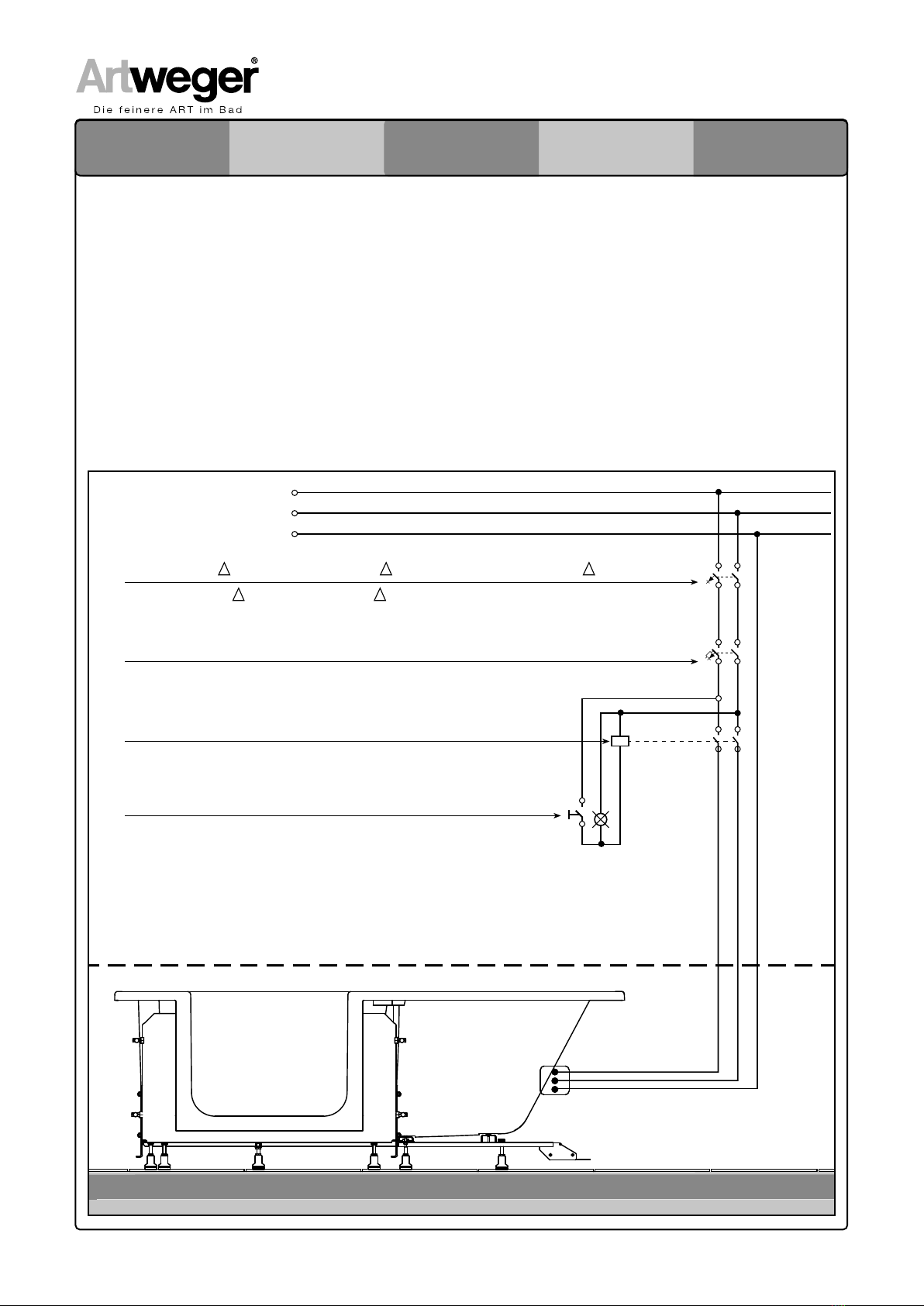
DEDie Elektroinstallation darf nur von einem berechtigten Fachbetrieb unter Berücksichtigung der gesetzlichen Richtlinien sowie der nationalen Errichtungs-
bestimmungen erfolgen (z.B.: Österreich EN OVE E 8101; Deutschland DIN VDE 0100-701 in der jeweils gültigen Ausgabe).
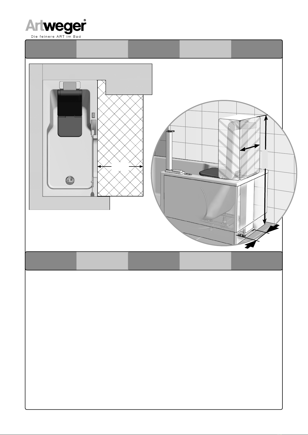
Leerrohr von oben bzw unten (mind. Ø 20 mm, Mindestverlegetiefe 5 cm). Separate Netzzuleitung H05-VV-F (flexible Leitung)
über FI-Schutzschalter RCD ∆IN ≤ 30 mA. Zum Anschluss sollten ca. 3m Kabel vorgesehen werden. Gültige Vorschriften für Potentialausgleich beachten!
Potentialausgleichsleitung, 4 mm2 (Cu) für den Anschluss an die serienmäßige Erdungsklemme.
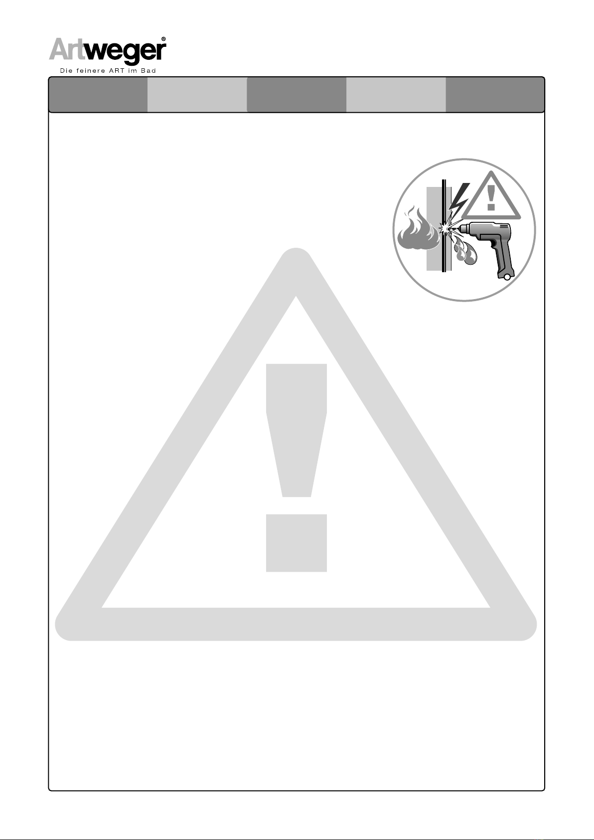
Die Leitung muß 2polig abschaltbar sein, mit min.3mm Kontaktöffnung (außerhalb von Schutzbereich 2) (z.b. Schütz geschalten über Lichtschalter mit
Kontrollanzeige) (Gemäß VDE 0100-701 bzw. EN OVE E 8101).
Teile, die aktive Teile enthalten, ausgenommen Teile, die mit Sicherheitskleinspannung nicht größer 12V versorgt werden, müssen für Personen im Bad
unzugänglich sein. Geerdete Geräte müssen dauerhaft an fest verlegte Leitungen angeschlossen sein.
ITL‘installazione elettrica può essere effettuata solamente da una ditta specializzata autorizzata osservando le disposizioni di legge e i regolamenti nazi-
onali relativi all‘installazione (ad es. Austria: EN OVE E 8101; Germania DIN VDE 0100-701 nelle edizioni in vigore). Canalina dall‘alto e dal basso ( min. Ø
20 mm, profondità minima di posa 5 cm). Cavo di allacciamento alla rete separato H05-VV-F (Cavo flessibile), su interruttore di protezione FI RCD ∆IN ≤
30 mA. Per l‘allacciamento si deve prevedere un cavo di ca. 3 mt. Prestare attenzione alle normative in vigore per il collegamento equipotenziale! Cavo di
collegamento equipotenziale, 4 mm2 (Cu) per il collegamento ai morsetti di messa a terra di serie.
Il cavo deve essere interrompibile a 2 poli, con un‘apertura di contatto di almeno 3 mm (ad eccezione dello spazio di protezione 2) (ad es. protezione
inserita su interruttore di luce con indicatore di controllo) (ai sensi del VDE 0100-701 e dell‘ EN OVE E 8101).
Apparecchi i quali racchiudono elementi mobili, all‘infuori di elementi alimentati a bassa tensione fino non superior a 12V, nel bagno devono
essere inaccessibili a persone .Apparecchi messi a massa devono essere allacciati permanentemente a condutture fisse.
ENElectrical installation may only be carried out by a qualified, registered company in compliance with legislation guidelines as well as the currently
valid edition of national installation regulations (e.g.; Austria EN OVE E 8101; Germany DIN VDE 0100-701).
Cable duct from above or below (min. 20 mm Ø, min. installation depth 5 cm). Separate mains supply line H05-VV-F (flexible line), over a RCD ∆IN
≤ 30 mA. For connection a cable of approx. 3 m should be provided. Take care to comply with current regulations about potential equalization! Potential
equalization line, 4 mm2 (Cu) for connection to the standard ground terminal.
The line has to have a double-pole cut-off, with a min. 3 mm contact opening (outside of protected zone 2) (e.g. protection switched over light switch with
control indicator) (in accordance with VDE 0100-701 respectively EN OVE E 8101).
Parts which contain live parts, except parts which have a safety current not higher than 12V, have to be made inaccessible to people in the bathtub; earthed
devices have to be permanently connected to static wiring.
FRL‘installation électrique ne peut être qu‘effectuée par une entreprise spécialisée sous la stricte observance des directives légales, ainsi que des dispositions nationales
liées à la construction (par ex.: Autriche EN OVE E 8101; Allemagne DIN VDE 0100-701 respectivement dans sa dernière version).
Gaine à partir du haut ou bien du bas (diamètre minimum 20 mm, profondeur d‘encastrement minimum 5 cm). Alimentation réseau séparée H05-VV-F (câble
flexible), par un interrupteur de sécurité FI RCD ∆IN ≤ 30 mA. Pour le raccordement il convient de prévoir environ 3 m de câble. Respecter les directives en
vigueur pour la compensation de potentiel ! Câble de compensation de potentiel, 4 mm2 (Cu) pour le raccordement à la borne de terre standard.
Le câble doit être muni d‘un dispositif d‘interruption bipolaire, avec une ouverture de contact de minimum 3 mm (en dehors de la zone de sécurité 2) (par ex.
contacteur branché sur interrupteur lumineux avec indication de contrôle) (Selon VDE 0100-701 ou bien EN OVE E 8101).
Les éléments, contenant des éléments actifs, excepté ceux alimentés avec une basse tension de sécurité ne dépassant pas 12V, doivent être inaccessibles
aux personnes dans la salle de bain. Les appareils avec un raccordement à la terre doivent être raccordés de manière permanente à l‘installation électrique
doméstique.
NLDe elektronische installatie mag slechts door een gespecialiseerd bedrijf, met inachtneming van de wettelijke richtlijnen en de nationale voorschriften betreffend
de inbouw, worden uitgevoerd (bijv. Oostenrijk EN OVE E 8101, Duitsland DIN VDE 0100-701 in de betreffend geldige uitgave).
Losse buis van boven naar beneden (min. Ø 20 mm, minimale plaatsingsdiepte 5 cm). Aparte nettoevoerleiding H05-VV-F (flexibele leiding), via
FI-veiligheidsschakelaar RCD ∆IN ≤ 30 mA Voor de aanleg moet tenminste rekening worden gehouden met ca. 3m kabel. Let op de geldende eisen voor de
potentiaalcompensatie! Leiding voor de potentiaalcompensatie 4 mm2 (Cu), voor de aansluitingen aan de standaard aardklem.
De leiding moet 2-polig uitgeschakeld kunnen worden, met minimaal 3mm contactopening (buiten de beschermde sector 2). (Bijvoorbeeld veiligheids-
schakelaar geschakeld via lichtschakelaar met controllampje.) (Volgens VDE 0100-701 resp. EN OVE E 8101).
Onderdelen die actieve bestanddelen bevatten, met uitzondering van onderdelen die zijn aangesloten op lage spanning niet meer dan 12V, moten buiten
bereik van personen in de badkamer blijvenGeaarde apparatuur moet altijd worden aangesloten op vaste bedrading.
7 / 24
ARTLIFTARTLIFT ARTLIFTARTLIFT
0,6 m
225 cm
A - A
Zone 1
Zone 2
Zone 0
60 cm
Zone 1
Schutzbereich 3
Protected area 3
Délimitation de protection 3
Zone 3
zona di sicurezza 3
Schutzbereich 0/1
Protected area 0/1
Délimitation de protection 0/1
Zone 0/1
zona di sicurezza 0/1
Schutzbereich 2
Protected area 2
Délimitation de protection 2
Zone2
Zona di sicurezza 2
AA
60 cm
60 cm
DEDie Schutzbereiche müssenzu Ihrer persönlichenSicherheit genau eingehalten werden.
Schutzbereich 2:(Höhe 225 cm) Verbot von Schaltern undSteckdosen!
EN For your personal safety, theprotected areas must be adhered to exactly.
Protected aera 2:(Height 225 cm) No switches or power outlets allowed!
FR Pour votre propre protection,les délimitations de protections sont à respecter exactement.
Délimitation niveau 2 :(Hauteur 225 cm) Interdiction de poser des interrupteurs ou des prises de courant !
NL Voor uw persoonlijke veiligheidmoeten de veiligheidszones nauwkeurig worden aangehouden.
Veiligheidszone 2:(hoogte 225 cm) verbod op schakelaars en stopcontacten!
ITPer la propria sicurezza le zone di sicurezza devono essere rispettate.
Zona di sicurezza 2:(altezza 225 cm) vietato posizionare interruttori e prese elettriche!
PROTECTED
AREAS
VEILIGHEIDS
ZONES
SCHUTZ-
BEREICHE
DÈLIMITATIONS DE
PROTECTION
ZONE DI
SICUREZZA
DEDie Schutzbereiche müssen zu Ihrer persönlichen Sicherheit genau eingehalten werden.
Schutzbereich 2:(Höhe 225 cm) Verbot von Schaltern und Steckdosen!
ENFor your personal safety, theprotected areas must be adhered to exactly.
Protected aera 2:(Height 225 cm) No switches or power outlets allowed!
FRPour votre propre protection,les délimitations de protections sont à respecter exactement.
Délimitation niveau 2 :(Hauteur 225 cm) Interdiction de poser des interrupteurs ou des prises de courant !
NLVoor uw persoonlijke veiligheidmoeten de veiligheidszones nauwkeurig worden aangehouden.
Veiligheidszone 2:(hoogte 225 cm) verbod op schakelaars en stopcontacten!
ITPer la propria sicurezza le zone di sicurezza devono essere rispettate.
Zona di sicurezza 2:(altezza 225 cm) vietato posizionare interruttori e prese elettriche!
8 / 24
ARTLIFTARTLIFT ARTLIFTARTLIFT
Leitungs-Schutzschalter max. 16A, Automatic cutout 16A max., Interrupteur de sécurité courant max. 16A,
2-polige schakelaar max.16A, fusibile max. 16A.
Schütz, Contactor, Fusible, Zekering, Relais.
Hoofdschakelaar met controlelamp in de badkamer,
interruttore con luce di controllo nel bagno
Hauptschalter mit Kontrolllampe im Bad, Main switch with control light in bathroom,
Interrupteur principal avec lampe de contrôle dans la salle de bain,
Anschluss, Connection, Raccordement,
Aansluiting, Allacciamento.
L
N
PE
L
N
PE
FI- Schutzschalter IN 30 mA, FI circuit breaker IN 30 mA, Interrupteur de sécurité FI IN 30 mA
FI- aardlekschakelaar IN 30 mA, salvavita RCD IN 30 mA.
Außerhalb des Schutzbereiches, Outside of protected area, En dehors de la délimitation de protection,
Buiten de veiligheidszone, al di fuori della zona di sicurezza
WIRING
DIAGRAMM
AANSLUIT
SCHEMA
SCHALT-
PLAN
PLAN DE
CÂBLAGE
SCHEMA
ELETTRICO
9 / 24
ARTLIFTARTLIFT ARTLIFTARTLIFT
MONTAGE-
SET
ASSEMBLY
KIT
SET DE
MONTAGE
MONTAGE
SET
CORREDO
DELL‘ASSEMBLEA
BENÖTIGTES
WERKZEUG
NECESSARY
TOOLS
OUTILLAGE
NECESSAIRE
BENODIGD
GEREEDSCHAP
ATTREZZATURE
NECESSARIA
3x M6x16mm
MatNr:24430
4x M6x20
MatNr:24274
1x SW5
MatNr:1880
1x SW4
MatNr:11750
400 mm
10 13
13
4x M8x35
MatNr:24270
2x M5x16
MatNr:24300
4x M4x12
MatNr:24377 2x M8
MatNr:24316
1x 41,2x5,7mm
MatNr:18639
6x
MatNr:24437 1x
MatNr:706638
6x
MatNr:706656
1x
1x
MatNr:18807
1x
10 / 24
ARTLIFTARTLIFT ARTLIFTARTLIFT
DE 1. Rückenlehne, Untertritt und
Schürzen entfernen.
2. Abdeckung der Wannendurchführung(a)
bzw. der Steuerung(b) abschrauben.
3. Ecksteher entfernen(c).
EN 1. Remove backrest, footboard
and skirting.
2. Unscrew the cover from the tub feed-
through (a) and the control (b).
3. Remove the corner support (c).
FR 1. Oter le dossier, le bandeau et
les tabliers
2. Dévisser le cache sur la zone aména-
gée dans la baignoire (a), ainsi que sur
l‘élément de pilotage (b).
3. Oter les supports d‘angle (c).
NL 1. Rugleuning, onderplint en
panelen verwijderen
2. Afdekking van de baddoorvoer (a) cq.
besturing (b) losschroeven.
3. Hoekpaal verwijderen (c).
IT 1. Rimuovere lo schienale, lo
zoccolo e la gonna.
2. Svitare la copertura del passante della
vasca (a) e l‘unità di comando (b).
3. Rimuovere il montante angolare (c).
PRE-
FITTING KIT
SET T.B.V.
VOORBEREIDINGEN
VORRÜST-
SATZ
SET DE PRÉ-
ÉQUIPEMENT
KIT DI
INSTALLAZIONE
a
b
c
11 / 24
ARTLIFTARTLIFT ARTLIFTARTLIFT
1
SW 13
13
170/180x80
170
180
160/170x75
170
160
SW 13
12 / 24
ARTLIFTARTLIFT ARTLIFTARTLIFT
X
S.16
2
2x M8
SW5
SW5
1.
2.
UP
UP
Nicht verkratzen!
Do not scratch!
Ne pas rayer!
Maak geen krassen!
Non graffiare! Ebener Bereich,
Flat area,
Partie plane,
Vlakke ondergrond,
Area piana.
M8x35mm
4x
innen
inside
intérieur
binnenkant
lato interno
13 / 24
ARTLIFTARTLIFT ARTLIFTARTLIFT
3
1.
2.
50mm
3.
4.
14 / 24
ARTLIFTARTLIFT ARTLIFTARTLIFT
SW 13
4
M6x16mm
3x
SW 10
10
SW 13
15 / 24
ARTLIFTARTLIFT ARTLIFTARTLIFT
SW5
M6x20
4x
M8x30
1x
5
16 / 24
ARTLIFTARTLIFT ARTLIFTARTLIFT
1.
2.
3.
M4x12
4x
DEStecker mit Steuerung verbinden
ENConnect plug to controller.
FRRaccoder la prise au le pilotage.
NLStekker met besturing verbinden.
IT Collegare il connettore con l‘unità di comando.
6
17 / 24
ARTLIFTARTLIFT ARTLIFTARTLIFT
DEStromanschluss herstellen.
ACHTUNG: Kabel nicht quetschen!
ENConnect to electricity supply.
ATTENTION: Do not squash the cable!
FRRéaliser le raccordement électrique.
ATTENTION: Ne pas pincer le câble !
NLElektrische aansluiting tot stand brengen.
OPGELET: Kabel niet bekneld laten raken!
7
LNPE
18 / 24
ARTLIFTARTLIFT ARTLIFTARTLIFT
DE1.Sitz hochfahren.
2.Kontrolle der Säule.
3.Ggf an den Stellfüssen justieren und
einrichten.
EN 1. Raise seat.
2. Check the post.
3. If necessary adjust the feet and level off.
FR 1. Elever le siège en position haute
2. Contrôler la colonne.
3. Au besoin ajuster les pieds et mettre de
niveau.
NL 1. Zitje omhoog bewegen
2. Controle van de zuil
3. Eventueel aan de stelpoten aanpassen
en vastzetten
IT 1. Disporre il sedile in alto.
2. Controllare il montante.
3. Eventualmente, regolare
e mettere a punto
1.
8
SW 13
3.
2.
3.
19 / 24
ARTLIFTARTLIFT ARTLIFTARTLIFT
DE1.Ecksteher einstzen
2.Steuerung mit Fussgestell verschrauben.
EN 1. Insert the corner support
2. Screw the control to the foot frame
Connect plug to controller.
FR 1. Positionner les supports
d‘angle.
2. Visser le pilotage avec le châssis de
pieds.
NL 1. hoekpaal plaatsen
2. besturing aan poten vastschroeven.
IT 1 Installare il montante angolare
2. Avvitare l‘unità di comando alla base.
1.
M5x20
2x
9
2.
20 / 24
ARTLIFTARTLIFT ARTLIFTARTLIFT
1x
10
A B
1x
DE Stellen Sie sicher, dass die Klebeflächen sauber sowie frei von Staub, Rost,
Verschmutzungen und Fett sind.
EN Make sure surfaces are clean and free from dust, rust, dirt and grease.
FR Assurez-vous que les surfaces soient propres et exemptes de poussière,
rouille, saleté et graisse.
NL Zorg ervoor dat de klevende oppervlakken schoon zijn en vrij van stof, roest,
vuil en vet.

Other manuals for ARTLIFT

3

This manual suits for next models

1

Other Artweger Lifting System manuals

Artweger ARTLIFT ALWA0 Series User manual

Artweger

Artweger ARTLIFT ALWA0 Series User manual

Artweger ARTLIFT ALWA0 Series User manual

Artweger

Artweger ARTLIFT ALWA0 Series User manual

Artweger ARTLIFT Troubleshooting guide

Artweger

Artweger ARTLIFT Troubleshooting guide

Popular Lifting System manuals by other brands

Sicor MR14 Operation and maintenance manual

Sicor

Sicor MR14 Operation and maintenance manual

morse 520 Operator's manual

morse

morse 520 Operator's manual

Maidesite AX05 user manual

Maidesite

Maidesite AX05 user manual

Youngman BOSS X Series Instructions for use

Youngman

Youngman BOSS X Series Instructions for use

MSA Lynx Hoist User instructions

MSA

MSA Lynx Hoist User instructions

Vacuworx RC 10 quick start guide

Vacuworx

Vacuworx RC 10 quick start guide

U-Line H-2708 manual

U-Line

U-Line H-2708 manual

Savaria Multilift Planning guide

Savaria

Savaria Multilift Planning guide

Zepro ZDK 250 135 installation instructions

Zepro

Zepro ZDK 250 135 installation instructions

Genie Z-45/25 Operator's manual

Genie

Genie Z-45/25 Operator's manual

Sealey MC390AH instructions

Sealey

Sealey MC390AH instructions

Titan TMR7B Operator's manual

Titan

Titan TMR7B Operator's manual

HALDER 22353.0008 Short instruction manual

HALDER

HALDER 22353.0008 Short instruction manual

Lift-Rite Altra Owner's Manual, Operating  Instructions Manual, and  Replacement Parts Manual

Lift-Rite

Lift-Rite Altra Owner's Manual, Operating Instructions Manual, and Replacement Parts Manual

Ranger Products BendPak P-6 Installation and operation manual

Ranger Products

Ranger Products BendPak P-6 Installation and operation manual

Genie Z-45/25 Operator's manual

Genie

Genie Z-45/25 Operator's manual

morse 510M Operator's manual

morse

morse 510M Operator's manual

Forankra PLM 100 TRANSLATION OF ORIGINAL INSTRUCTIONS

Forankra

Forankra PLM 100 TRANSLATION OF ORIGINAL INSTRUCTIONS

manuals.online logo
manuals.online logoBrands
  • About & Mission
  • Contact us
  • Privacy Policy
  • Terms and Conditions

Copyright 2025 Manuals.Online. All Rights Reserved.