manuals.online logo
Brands
  1. Home
  2. •
  3. Brands
  4. •
  5. Ascent
  6. •
  7. Keypad
  8. •
  9. Ascent 25-K1 User manual

Ascent 25-K1 User manual

Popular Keypad manuals by other brands

AAA 6150RFAAA Installation and setup guide

AAA

AAA 6150RFAAA Installation and setup guide

Fermax MDS Installation and programming manual

Fermax

Fermax MDS Installation and programming manual

ACT ACT PRO 1030 manual

ACT

ACT ACT PRO 1030 manual

Cardin SSB Series manual

Cardin

Cardin SSB Series manual

Harman Kardon KP 1 Specifications

Harman Kardon

Harman Kardon KP 1 Specifications

CYP CR-KP1 Operation manual

CYP

CYP CR-KP1 Operation manual

Aeware k-35 Series Quick reference card

Aeware

Aeware k-35 Series Quick reference card

Aritech CS-175 Series user guide

Aritech

Aritech CS-175 Series user guide

Lenze AC Tech MC SERIES installation instructions

Lenze AC Tech

Lenze AC Tech MC SERIES installation instructions

Burg Wächter secuENTRY 7711 operating instructions

Burg Wächter

Burg Wächter secuENTRY 7711 operating instructions

Aeware in.k450 Tech book

Aeware

Aeware in.k450 Tech book

Lenze EPM-H410 operating instructions

Lenze

Lenze EPM-H410 operating instructions

Toshiba RKP007Z user manual

Toshiba

Toshiba RKP007Z user manual

Elmes Electronic KB1 quick start guide

Elmes Electronic

Elmes Electronic KB1 quick start guide

Clare Controls ClareOne CLR-C1-PNC Installation sheet

Clare Controls

Clare Controls ClareOne CLR-C1-PNC Installation sheet

FM Electronics 4180 quick start guide

FM Electronics

FM Electronics 4180 quick start guide

AMX MIO-PRESTIGE-S Dimensional drawing

AMX

AMX MIO-PRESTIGE-S Dimensional drawing

why pro WHY-KP user manual

why pro

why pro WHY-KP user manual

manuals.online logo
manuals.online logoBrands
  • About & Mission
  • Contact us
  • Privacy Policy
  • Terms and Conditions

Copyright 2025 Manuals.Online. All Rights Reserved.

1Carefully unpack box and make sure you have all items
shown below.
1 of 4
QUICK START GUIDE
2Unlock and open front panel
of unit for wiring and setup.
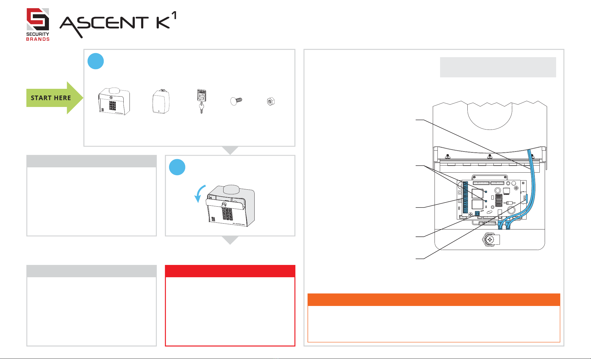
What’s what?
Important components labeled
WARNING!
AUTOMATIC GATES CAN CAUSE
SERIOUS INJURY OR DEATH!
ALWAYS CHECK that the GATE PATH
IS CLEAR BEFORE OPERATING!
Reversing or other safety devices
should ALWAYS BE USED!

IMPORTANT!
r
Ascent WILL NOT WORK until the
activation process is COMPLETE!
Follow the Activation Guide or call
Summit Control at (844) 259-8265 to
activate your unit.
Continued on next page...
Please use all four screws when mounting unit to pedestal. Leave “hockey puck” antenna
in place, even if using extension. Seal any holes or gaps created in unit enclosure.
Failure to follow these instructions can result in damage to the unit!
CAUTION!

Unit shown with front panel fully open.
Internal wiring not shown for clarity.
Ascent Unit Key Carriage Bolt
( x4 )
Hex Nut
( x4 )
12-V AC/DC Adapter
(PS-12DC1)
Model 25-K1
Connection Terminals
For wiring to all external devices including
gate operator or door opener
Power Terminals
For wiring to compatible AC/DC power source
SIM Card
If you have your own SIM card, see Page 4
and follow the instructions entitled,
Installing a Third-Party SIM Card.
Relay Status LEDs
Relay is active when lit
Antenna Cables
We recommend mounting Ascent on a
gooseneck pedestal using included hardware.
If using alternate mounting, two (2)
Ascent 10' Cable Extension (p/n 16-X-EXT)
products should be purchased and installed.
Failure to do so may result in NO SIGNAL!
IMPORTANT!
r
2 of 4
QUICK START GUIDE
4Close and lock front panel.
Now follow the Activation Guide to create
an account and begin using Ascent.
INSTALLATION COMPLETE!
N
Before going forward,
double check wiring and
ensure unit has power!
For additional wiring
options, see Page 3.
STOP!

2 20 1
5Make sure gate path is clear, then
key in temporary code 2012 on
keypad and confirm gate opens.
Adding and deleting codes is done through
Summit Control and NOT from the keypad!
Additional wiring diagrams
can be found on Page 3.
Consult gate operator or
door opener manual for
exact connections.
Terminals vary widely
across manufacturers
and models.
3Connect wires
Feed wires through back of unit
and connect as shown.
Ascent Connection Terminals
Ascent
Power
Terminals
12–24 VAC/DC
POWER
12–24 VAC/DC
POWER
RELAY ARELAY BEVENTDIGITAL INPUTSSTATUS
Gate Operator / Door Opener
POS. (+)
NEG. (–)
COM
RADIO
COM
REVERSE LOOP
COM
OPEN
STOP
CLOSE
12-V AC/DC Adapter
(Model PS-12DC1 included)
The GROUND terminal is optional unless
required by local code(s). If using, please
connect to earth ground or equivalent.
OR
Third-Party 12–24-VAC/DC
Power Source
Relay B can be wired to a second device
in the same manner.
N/C
COM
FREE EXIT
COM
N/O
N/C
COM
N/O
CLOSE
GND
OPEN
GND
N/O
GND
# 2
GND
# 1
POS. (+)
NEG. (–)
+–
J7 J8
J3
J9 J6 J5 J4
Model 25-K1
QSG-25K1-EN Rev. D (6/2018)
© 2018 Security Brands, Inc. All rights reserved.
If you will not be using the 12-V AC/DC adapter,
please go to Page 4 and follow the procedure,
Using a Third-Party Power Source.
Do not exceed 24 VAC/DC! Failure to choose a
compatible power source can damage unit!
CAUTION!

If plugging into duplex outlet,
remove screw from outlet plate,
and secure with included screw.
3 of 4
QUICK START GUIDE Model 25-K1
RELAY ARELAY BEVENTDIGITAL INPUTSSTATUS
J7 J8 J9 J6 J5 J4
AStatus Check
Wiring to enable Gate Status Check
(if equipped with limit switches)
Open Limit Switch
Close Limit Switch
Optional
wire
splices
N/C
N/C
Gate Operator
BEvent Input
Wiring for accessories such as a request-to-exit device
Request-to-Exit
(S-RTE-P is shown)
Connected as
shown in Step 3
Ascent Connection Terminals
RELAY ARELAY BEVENTDIGITAL INPUTSSTATUS
N/C
N/C
COM
N/O
GND
N/O
GND
# 2
GND
# 1
J7 J8 J9 J6 J5 J4
COM
N/O
COM
N/O
CLOSE
GND
OPEN
COM
N/O
Connected as
shown in Step 3
Ascent Connection Terminals
N/C
N/C
COM
N/O
GND
# 2
GND
# 1
CLOSE
GND
OPEN
COM
N/O
GND
N/O
The Status Terminals are designed for
low voltage (3 V or less). Check the
voltage on your status wires before
connecting. If it is above 3 V, you will
need to contact Technical Support.
Exceeding 3 V can damage Ascent!
CAUTION!

4 of 4
3a Connect wires to unit as shown in
Step 3.
3b Connect wires to your power source,
making sure you connect positive to
positive and negative to negative.
CAUTION!

Double check that you’ve wired from
positive on Ascent to positive on your
power source and negative on Ascent to
negative on your power source.
Reverse polarity can damage Ascent!
Installing a
Third-Party
SIM Card
(Optional)
Using a
Third-Party
Power Source
(Optional)
IMPORTANT!
r
If you would like to use a third-party
power source, such as solar, verify that
it conforms to the following specs:
Input 12–24 VAC/DC
no more than 10% beyond this range
Current Draw less than 190 mA @ 12 VDC
less than 160 mA @ 24 VDC
QUICK START GUIDE
1Push existing SIM card in until it
unlocks with “click” sound. 2Remove existing SIM card and locate
new SIM card. 3Insert new SIM card until it locks in
place with “click” sound.
Model 25-K1
?NEED HELP Call (844) 259-8265
Email [email protected]
We are available Mon–Fri / 8am–5pm Central
© 2018 Security Brands, Inc. All rights reserved. QSG-25K1-EN Rev. D (6/2018)