Asco 430 User manual

Surge Protective Devices Installation & Operation Manual
Model 430

© 2020 ASCO Power Technologies. All Rights Reserved
For troubleshooting, call technical assistance at 1-800-237-4567 or customercare@ascopower.com
2
IO-70061
01/2020

© 2020 ASCO Power Technologies
All Rights Reserved
Model 430 Surge Protective Device (SPD)
Table of Contents
IO-70061
3
Precautions
Introduction
Unpacking and Preliminary Inspection
Storage
Identication Nameplate
SPD Location Considerations
Environment
Audible Noise
Mounting
Service Clearance
Equipment Performance
Electrical
Voltage Rating
Branch Circuit Overcurrent Protection and Disconnect Means
Location of Surge Protective Device (SPD)
System Grounding
Wiring
ASCO 430 Wiring Diagrams
Installation
Surface Mount Installation
Flush Mount Installation
Operation
LED Status Indicators
Audible Alarm
Dry Contacts
Remote Monitor Option
Preventive Maintenance
3
4
5
5
5
5
5
5
5
5
5
6
6
7
7
8
9
11
13
13
14
14
15
15
15
16
17

© 2020 ASCO Power Technologies. All Rights Reserved
For troubleshooting, call technical assistance at 1-800-237-4567 or customercare@ascopower.com
4
IO-70061
01/2020
Safety Information
Important Information
Read these instructions carefully and look at the equipment to become
familiar with the device before trying to install, operate, service or maintain it.
The following special messages may appear throughout thisbulletin or on the
equipment to warn of potential hazards or to call attention to information that
clarifies or simplifies a procedure.
The addition of either symbol to a “Danger”or “Warning” safety label
indicates that an electrical hazard exists which will result inpersonal
injury if the instructions are not followed.
This is the safety alert symbol. It is used to alert you to potential
personal injury hazards. Obey all safety messagesthat follow this
symbol to avoid possible injury or death.
DANGER
DANGER indicates a hazardous situation which, if not avoided,
will result in death or serious injury.
WARNING
WARNING indicates a hazardous situation which, if not avoided,
could result in death or serious injury.
CAUTION
CAUTION indicates a hazardous situation which, if not avoided,
could result in minor or moderateinjury.
NOTICE
NOTICE is used to address practices not related to physical injury. The safety
alert symbol shall not be used with this signal word.
Please Note
Electrical equipment should be installed, operated, serviced, and maintained only
by qualified personnel. No responsibility is assumed by ASCO Power Technologies
for any consequences arising out of the use of this material.
A qualified person is one who has skills and knowledge related to the
construction, installation, and operation of electrical equipment andhas received
safety training to recognize and avoid the hazards involved.

© 2020 ASCO Power Technologies. All Rights Reserved
For troubleshooting, call technical assistance at 1-800-237-4567 or customercare@ascopower.com
5
IO-70061
01/2020
ASCO 430 Surge Protective Device (SPD)
Precautions
Precautions
HAZARD OF ELECTRIC SHOCK, EXPLOSION, OR ARC FLASH
• Apply appropriate personal protective equipment (PPE) and follow safe
electrical work practices. See NFPA 70E, NOM-029-STPS or CSA Z462.
• This equipment must only be installed and serviced by qualied electri-
cal personnel.
• Turn o all power supplying this equipment before working on or inside
equipment.
• Always use a properly rated voltage sensing device to conrm power is o.
• Replace all devices, doors and covers before turning on power to this
equipment.
• This equipment must be eectively grounded per all applicable codes.
Use an equipment-grounding conductor to connect this equipment to the
power system ground.
Failure to follow these instructions will result in death or serious injury.
WARNING: This product can expose you to chemicals including
DINP, which is known to the State of California to cause cancer, and
DIDP which is known to the State of California to cause birth defects
or other reproductive harm. For more information go to: www.
P65Warnings.ca.gov.
NOTICE
LOSS OF BRANCH CIRCUIT POWER / LOSS OF SURGE
SUPPRESSION
• Perform periodic inspection of the surge protective device status
indicator lights as part of the preventative maintenance schedule.
• Promptly replace the surge protective device when an alarm state
exists.
• Use dry contacts to signal an alarm state to the central supervisory
system for unmanned, inaccessible, or critical installations.
• Use multiple surge protective devices to achieve redundancy for critical
applications.
Failure to follow these instructions can result in equipment damage.
At end-of-life conditions, Surge Protective Devices (SPDs) can lose their
ability to suppress power system transient voltage spikes and attempt to
draw excessive current from the line. This SPD is equipped with overcurrent
and overtemperature components that will automatically disconnect the
surge suppression elements from the mains should the surge suppression
elements reach end of life. Tripping of the branch circuit breaker or fuse
feeding the SPD can occur. Mitigate the tripping of the branch circuit breaker
or fuse feeding the SPD by coordinating the surge suppression elements
with the branch circuits.
DANGER

© 2020 ASCO Power Technologies. All Rights Reserved
For troubleshooting, call technical assistance at 1-800-237-4567 or customercare@ascopower.com
6
IO-70061
01/2020
ASCO 430 Surge Protective Device (SPD)
Introduction
HAZARD OF ELECTRIC SHOCK, EXPLOSION, OR ARC FLASH
• Do not energize the surge protective device until the electrical system is
completely installed, inspected and tested.
• Ensure all conductors are connected and functional.
• Verify the voltage rating of the device and system prior to energizing.
• Perform high-potential insulation testing, or any other tests where surge
protective device components will be subjected to voltages higher than
their rated turn-on voltage, with the neutral and surge protective device
disconnected from the power source
Failure to follow these instructions will result in death or serious injury.
HAZARD OF ELECTRIC SHOCK, EXPLOSION, OR ARC FLASH
• Apply appropriate personal protective equipment (PPE) and follow safe
electrical work practices. See NFPA 70E, NOM-029-STPS or CSA Z462.
• This equipment must only be installed and serviced by qualied
electrical personnel.
• Turn o all power supplying this equipment before working on or inside
equipment.
• Always use a properly rated voltage sensing device to conrm power is
o.
• Replace all devices, doors and covers before turning on power to this
equipment.
• This equipment must be eectively grounded per all applicable codes.
Use an equipment-grounding conductor to connect this equipment to the
power system ground.
Failure to follow these instructions will result in death or serious injury.
Proper installation is imperative to maximize the ASCO 430 SPDs eective-
ness and performance. Follow the steps outlined in this instruction bulletin
to ensure proper installation. Read the entire instruction bulletin before
beginning the installation. These instructions are not intended to replace
national or local electrical codes. Check all applicable electrical codes to
verify compliance. Installation of ASCO 430 surge suppressors must only be
performed by qualied electrical personnel.
DANGER
DANGER
Introduction
Note: For troubleshooting, call technical
assistance at 1-800-237-4567 or
customercare@ascopower.com

© 2020 ASCO Power Technologies. All Rights Reserved
For troubleshooting, call technical assistance at 1-800-237-4567 or customercare@ascopower.com
7
IO-70061
01/2020
ASCO 430 Surge Protective Device (SPD)
Unpacking and Preliminary Inspection
Unpacking and Preliminary
Inspection
Storage
Identication Nameplate
SPD Location
Considerations
Environment
Audible Noise
Mounting
Service Clearance
Equipment Performance
Inspect the entire shipping container for damage or signs of mishandling be-
fore unpacking the device. Remove the packing material and further inspect
the device for any obvious shipping damage. If any damage is found and is
a result of shipping or handling, immediately le a claim with the shipping
company.
The device should be stored in a clean, dry environment. Storage tempera-
ture is -40° F to +140° F (-40° C to +60° C). All of the packaging materials
should be left intact until the device is ready for installation.
The identication nameplate is located on the side of the unit.
The device is designed to operate in an ambient temperature range of
-13 °F to +140 °F (-25°C to +60°C) with a relative humidity of 0 to 95%
non-condensing. This device has a Type 4X housing.
The device background noise is negligible and does not restrict the location
of the installation.
The device has been designed to be surface mounted. An additional ush
mount kit is also available if required (KITFMXF) or stainless steel ush
mount kit (KITFMXFSS).
The service clearance should meet all applicable code requirements.
To obtain optimum surge suppression, locate the SPD as close as possible
to the circuitry being surge-limited to minimize the wire length. Minimizing
the wire length reduces the impedance between the circuitry and the SPD.
Refer to the Voltage Protection Rating (VPR) values on the SPD nameplate.
These VPR values were obtained by testing the SPD with six-inch long
leads (per UL1449). For every additional foot of wire beyond six inches, the
eective VPR increases by approximately 160 volts.
ASCO POWER TECHNOLOGIES, LP
CAT# 430_____________
PART# __XDS__________
VOLTAGE: ____________V 50-60Hz
MAX RATED AMBIENT AIR TEMP: ________
MFG DATE: _________
Suitable for use on a circuit capable of delivering not more
than _________ rms symmetrical amperes
ENC TYPE: XXXX
In: 20 kA
____V
VOLTAGE
PROTECTION RATING
CW
UL 1449-4
SPD TYPE __
MCOV: ____ / _____
L-N
L-G
N-G
L-L
____
____
____
____
UL
Holigram

© 2020 ASCO Power Technologies. All Rights Reserved
For troubleshooting, call technical assistance at 1-800-237-4567 or customercare@ascopower.com
8
IO-70061
01/2020
ASCO 430 Surge Protective Device (SPD)
Electrical
HAZARD OF ELECTRIC SHOCK, EXPLOSION, OR ARC FLASH
Conrm the surge protective device voltage rating on the module or
nameplate label is not less than the operating voltage.
Failure to follow these instructions will result in death or serious injury.
Prior to mounting the SPD, verify that the device has the same voltage
rating as the power distribution system in which it is installed. Compare the
nameplate voltage or model number on the SPD with the nameplate of the
electrical distribution equipment.
The specier or user of the device should be familiar with the conguration
and arrangement of the power distribution system in which the SPD is to be
installed. The system conguration of any power distribution system is based
strictly on how the secondary windings of the transformer supplying the ser-
vice entrance main or load are congured. This includes whether or not the
transformer windings are referenced to earth via a grounding conductor. The
system conguration is not based on how any specic load or equipment
is connected to a particular power distribution system. See Table 1 for the
service voltage of each SPD.
Electrical
Voltage Rating
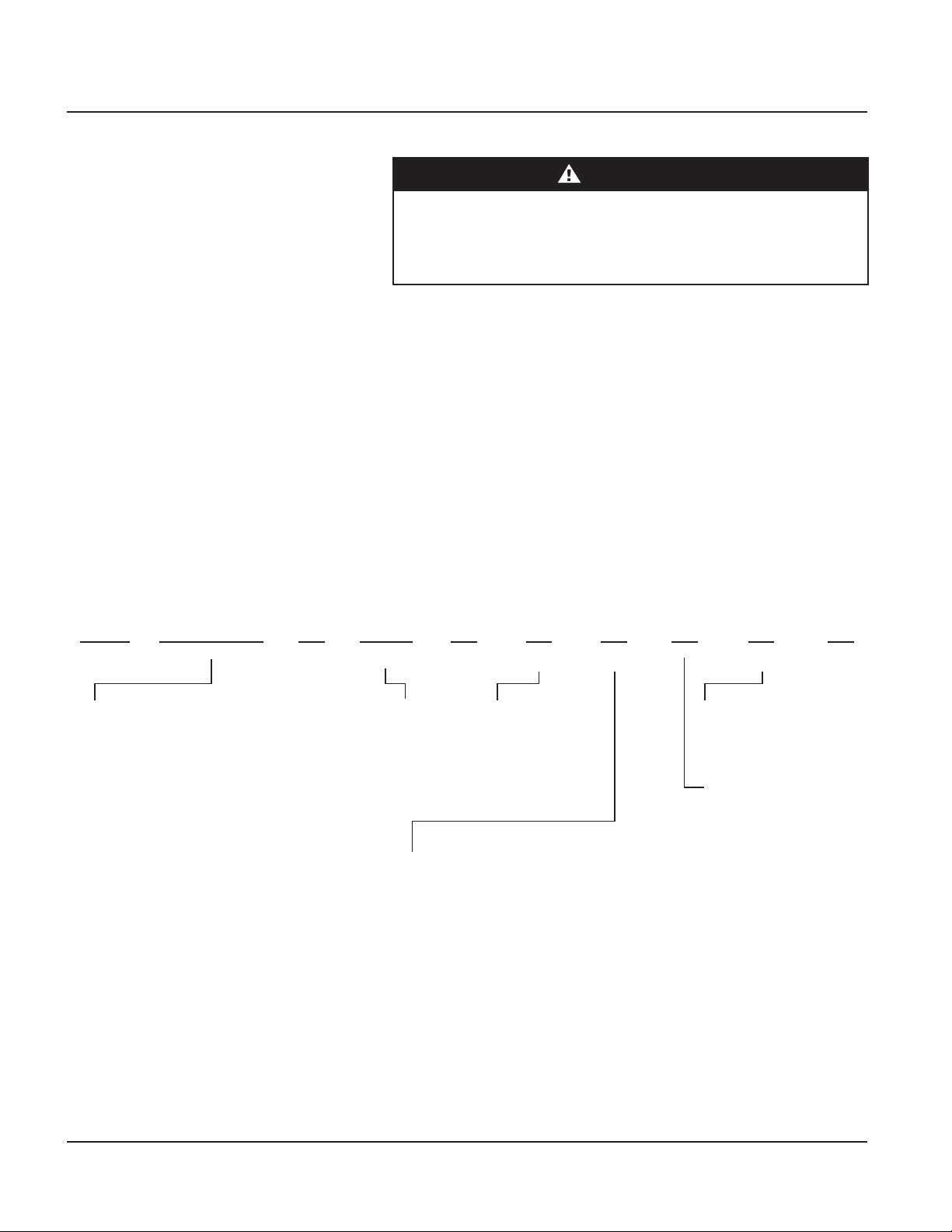
Table 1: Model 430 Service Voltages
DANGER
Voltage Codes
P C JA
Per Phase
kA Rating
System
Modes of
Protection
(Default)
Connection
Type
Monitoring
Options
Enclosure
UL 1449
Type1/Type 2
0
Option(s)kA Rating
Per Phase
430
Model 430
Product Line
J = NEMA 4X Non-Metallic
(Polycarbonate)
Size - 6” x 6” x 4”
C = Compression
Lugs
S =
LEDs
A = LEDs/Audible Alarm/Relay
1 = UL 1449 Type 1
2 = UL 1449 Type 2,
(Includes UL1283
Filter)
10 = 100kA
15 = 150kA
20 = 200kA
120S = 120/240V Split Phase - 1Ø, 3W+Grnd
120Y = 208Y/120V Wye - 3Ø 4W+Grnd
240H = 240/120V High Leg Delta (B High)
277Y = 480Y/277V Wye - 3Ø 4W+Grnd
347Y = 600Y/347V Wye - 3Ø 4W+Grnd
480D = 480V Delta - 3Ø 3W+Grnd & HRG Wye
120N = 120V Single Phase
127N = 127V Single Phase
127S = 127/254V Split Phase - 1Ø 3W+Grnd
127Y = 220Y/127V Wye - 3Ø 4W+Grnd
220Y = 380Y/220V Wye - 3Ø 4W+Grnd
230Y = 400Y/230V Wye - 3Ø 4W+Grnd
240N = 240V Single Phase - Not split phase
240S = 240/480V Split Phase - 1Ø, 3W+Grnd
240Y = 415Y/240V Wye - 3Ø 4W+Grnd
240C = 240V B Corner Grnd Delta, 3Ø 3W+Grnd
240D = 240V Delta - 3Ø 3W+Grnd
254Y = 440Y/254V Wye - 3Ø 4W+Grnd
277N = 277V Single Phase
300N = 300V Single Phase
300Y = 520Y/300V Wye - 3Ø 4W+Grnd
480N = 480V Single Phase (1 Hot, 1 Neu, 1 Grnd)
480C = 480V B Corner Grnd Delta, 3Ø 3W+Grnd
600C = 600V B Corner Grnd Delta, 3Ø 3W+Grnd
600D = 600V Delta - 3Ø 3W+Grnd & HRG Wye

© 2020 ASCO Power Technologies. All Rights Reserved
For troubleshooting, call technical assistance at 1-800-237-4567 or customercare@ascopower.com
9
IO-70061
01/2020
ASCO 430 Surge Protective Device (SPD)
Electrical
Branch Circuit Overcurrent
Protection and Disconnect Means
Location of Surge Protective
Device (SPD)
HAZARD OF ELECTRIC SHOCK, EXPLOSION, OR ARC FLASH
• Use conductors rated for the Overcurrent Protection Device (OCPD) per
applicable codes.
• Use conductors rated for the application per applicable codes.
Failure to follow these instructions will result in death or serious injury.
A branch circuit Overcurrent Protection Device (OCPD) either in the form of
a circuit breaker or fuse must be provided for the ASCO 430 Type 2 device.
The branch circuit OCPD should either provide or include a disconnecting
means.
Since the current drawn by the ASCO 430 device during normal operation is
negligible, the ASCO 430 device can be connected to a dedicated, separate
branch circuit or connected to a suitable existing branch circuit.
When connected to a separate, dedicated branch circuit, the OCPD setting
must be selected to protect the conductors feeding the ASCO 430 device
per applicable state and local building codes.
UL 1449 Type 1 SPDs have been designed and approved for line side appli-
cations prior to the main service disconnect without supplemental overcur-
rent protection. Type 2 SPDs must be installed on the load side of the main
Overcurrent Protective Device (OCPD). All installations should either provide
or include a disconnecting means.
Type 1 SPDs can also be used in Type 2 applications (load side of OCPD).
When either Type 1 or Type 2 SPDs are used on the load side, they must be
installed per local codes.
Locate the SPD as close as possible to the circuit mains being surge-limited
to minimize the wire length and optimize SPD performance. Avoid long wire
runs so that the device will perform as intended. To reduce the impedance
that the wire displays to surge currents, the phase, neutral, and ground
conductors (wye and high-leg delta congurations), or phase and ground
conductors (delta congurations), must be routed within the same conduit
and tightly bundled or twisted together to optimize device performance.
Avoid sharp bends in the conductors. See Figures 2 and 3.
Figure 2: SPD Wiring for Wye and High-Leg Delta Congurations
DANGER
To load(s)
Phases
Neutral
Ground
Ground bus
Neutral bus
SPD
Phase A
Phase B
Phase C
Neutral
Ground
Panel
Interconnect wiring
– Minimize length
– Avoid sharp bends

© 2020 ASCO Power Technologies. All Rights Reserved
For troubleshooting, call technical assistance at 1-800-237-4567 or customercare@ascopower.com
10
IO-70061
01/2020
ASCO 430 Surge Protective Device (SPD)
System Grounding
Figure 3: SPD Wiring for Delta Congurations
To load(s)
Phases
Ground
Phase A
Phase B
Phase C
Ground
SPD
Interconnect wiring
– Minimize length
– Avoid sharp bends
HAZARD OF ELECTRIC SHOCK, EXPLOSION, OR ARC FLASH
• Ungrounded power systems are inherently unstable and can produce
excessively high line-to-ground voltages during certain electrical
fault conditions. Durign these electrical fault conditions any electrical
equipment, including a surge protective device, may be subjected to
voltages which exceed their designed ratings.
• Make an informed decision before installing any electrical equipment on
an ungrounded power system.
Failure to follow these instructions will result in death or serious
injury.
NOTICE
LOSS OF SURGE SUPPRESSION
• Verify that the service entrance equipment is bonded to ground in
accordance with all applicable codes.
Failure to follow these instructions can result in equipment damage.
The ASCO 430 has SPD elements connected from phase to ground. It
is critical that there be a robust and eective connection to the building
grounding structure. The grounding connection must utilize an equipment
grounding conductor run with the phase and neutral connection of the
power system. Do not connect the SPD to a separate isolated ground.
For proper voltage suppression by the ASCO 430 SPD, use a single-point
ground system where the service entrance grounding electrode system is
connected to, and bonded to, all other available electrodes, building steel,
metal water pipes, driven rods, etc. (for reference, see NEC Art 250). The
ground impedance measurement of the electrical system must be as low as
possible and in compliance with all applicable codes for sensitive electronic
and computer systems.
System Grounding DANGER

© 2020 ASCO Power Technologies. All Rights Reserved
For troubleshooting, call technical assistance at 1-800-237-4567 or customercare@ascopower.com
11
IO-70061
01/2020
ASCO 430 Surge Protective Device (SPD)
Wiring
Wiring
NOTICE
LOSS OF SURGE SUPPRESSION
• Install an insulated grounding conductor inside a metallic raceway when
the raceway is used as an additional grounding conductor. Size the
conductor in accordance with all applicable codes.
• Maintain adequate electrical continuity at all raceway connections.
• Do not use isolating bushings to interrupt a metallic raceway run.
• Do not use a separate isolated ground for the surge protective device.
• Verify proper equipment connections to the grounding system.
• Verify ground grid continuity by inspections and testing as part of a
comprehensive electrical maintenance program.
Failure to follow these instructions can result in equipment damage.
HAZARD OF ELECTRIC SHOCK, EXPLOSION, OR ARC FLASH
• Apply appropriate personal protective equipment (PPE) and follow safe
electrical work practices. See NFPA 70E, NOM-029-STPS or CSA Z462.
• This equipment must only be installed and serviced by qualied electri-
cal personnel.
• Turn o all power supplying this equipment before working on or inside
equipment.
• Always use a properly rated voltage sensing device to conrm power is
o.
• Replace all devices, doors and covers before turning on power to this
equipment.
• This equipment must be eectively grounded per all applicable codes.
Use an equipment-grounding conductor to connect this equipment to the
power system ground.
• Conrm the surge protective device voltage rating on the module or
nameplate label is not less than the operating voltage.
Failure to follow these instructions will result in death or serious injury.
DANGER

© 2020 ASCO Power Technologies. All Rights Reserved
For troubleshooting, call technical assistance at 1-800-237-4567 or customercare@ascopower.com
12
IO-70061
01/2020
ASCO 430 Surge Protective Device (SPD)
Wiring
Follow steps 1 through 7 to make wiring connections:
1. Turn o all power supplying this equipment before working on or inside
any enclosure containing this equipment.
2. Conrm SPD is rated for your system by comparing voltage measure-
ments to the Line Voltage (L-L, L-N) on the product label.
3. Identify proper location for the SPD. Locate as close as possible to
the mains of the panel being surge-limited so the wires are as short as
possible. Mount unit securely.
Note: The SPD must be installed in an accessible location (not within
walls unless surface mounted with the ASCO KITFMXF ush mount
kit).
4. Install in accordance with national and local electrical codes and match
the branch circuit Overcurrent Protection Device (OCPD) to the wire
size.
5. Twist conductors 1/2 turn or more for every twelve inches of length.
6. Do not loop or coil wires. Be sure to maintain adequate wire bending
space per NEC.
7. Use on solidly grounded systems unless the SPD model is designed for
installation on ungrounded/HRG systems.
HAZARD OF ELECTRIC SHOCK, EXPLOSION, OR ARC FLASH
For outdoor installation use and appropriate weather sealing at the nipple
(o-ring, sealing conduit, etc).
Failure to follow these instructions will result in death or serious injury.
Figure 4: Conduit Installation
Table 2: Wiring Diagram Location1
Wiring for: Figure and
Page
Single-phase, three-wire,
grounded installation
Figure 6 on
page 11
Single-phase, two-wire, +
ground
Figure 7 on
page 11
Three-phase, three- or
four-wire, grounded WYE
installation
Figure 8 on
page 12
Three-phase, three- or
four-wire, high-leg delta
installation
Figure 9 on
page 12
Three-phase, three-wire +
ground, delta installation
Figure 10 on
page 12
Three-Phase, Three-Wire,
Corner Grounded, Delta
Installation
Figure 11 on
page 12
1 See “Dry Contacts” on page 15 for dry contact wiring. DANGER
CORRECT
INSTALLATION
Threaded 6
Full Turns
INCORRECT INSTALLATIONS
OVERTIGHTENED
Stresses box,
ONLY
6 full turns
required
POOR
ENGAGEMENT
Conduit needs
to be threaded
in farther

© 2020 ASCO Power Technologies. All Rights Reserved
For troubleshooting, call technical assistance at 1-800-237-4567 or customercare@ascopower.com
13
IO-70061
01/2020
ASCO 430 Surge Protective Device (SPD)
Wiring
Figure 5: Typical panel Installation
Figure 6: Single-Phase, Three-Wire, Grounded Installation
Figure 7: Single-Phase, Two-Wire, Ground
V
}
Neutral (White)
Phase A (Black)
Ground (Green)
CONTACTS
NO CNC
DRY
SERVICE
AC
B
NG
Installation, Operation and Maintenance Manual IO-70061 RevJ 09-18
AB C
GN
BREAKER
Use closest breaker to SPD
Locate SPD close to intended breaker
Keep Leads Short as Possible
Avoid Sharp Bends
Rotate Model 430 such
that LED indicator is most
visible
Outdoor installation requires appropriate weather
sealing at nipple (o-ring, sealing conduit, etc.)
Loads

© 2020 ASCO Power Technologies. All Rights Reserved
For troubleshooting, call technical assistance at 1-800-237-4567 or customercare@ascopower.com
14
IO-70061
01/2020
Figure 8: Three-Phase, Three- or Four-Wire, Grounded WYE Installation1
Figure 9: Three-Phase, Three- or Four-Wire, High-Leg Delta Installation2
Figure 10: Three-Phase, Three-Wire, Delta Installation
Figure 11: Three-Phase, Three-Wire, Corner Grounded, Delta Installation
ASCO 430 Surge Protective Device (SPD)
Wiring
Note 1: The neutral conductor is not present on
three-wire Wye grounded power systems. For
improved operation of the SPD, bond the neutral
and ground lugs together inside the SPD.
Phase A (Black)
Phase C (Black)
Ground (Green)
V
}
CONTACTS
NO CNC
DRY
SERVICE
AC
TWO POLE
AC
G
HAZARD OF ELECTRIC SHOCK,
EXPLOSION, OR ARC FLASH
• The high-leg of the power system must
connect to the B phase lug of the SPD.
Failure to follow these instructions will result
in death or serious injury.
Note 2: The neutral conductor is not present
on three-wire High-Leg Delta grounded power
systems. For improved operation of the SPD,
bond the neutral and ground lugs together inside
the SPD.
DANGER

© 2020 ASCO Power Technologies. All Rights Reserved
For troubleshooting, call technical assistance at 1-800-237-4567 or customercare@ascopower.com
15
IO-70061
01/2020
6.0
6.0
6.0
5.3
7.5
6.7
(152.4)
(152.4)
(152.4)
(136.1)
(191.6)
(172.5) Ø 0.3
(Ø 7.9)
0.8
(22.2)
3.4
(86.6)
3.9
(99.7)
Ø 1.0
(Ø 25.4)
3.4 in. (25.4 mm) Female NPT thread
Figure 11: General Dimensions (in. / mm.)
ASCO 430 Surge Protective Device (SPD)
Installation
HAZARD OF ELECTRIC SHOCK, EXPLOSION, OR ARC FLASH
• Apply appropriate personal protective equipment (PPE) and follow safe
electrical work practices. See NFPA 70E, NOM-029-STPS or CSA Z462.
• This equipment must only be installed and serviced by qualied electri-
cal personnel.
• Turn o all power supplying this equipment before working on or inside
equipment.
• Always use a properly rated voltage sensing device to conrm power is
o.
• Replace all devices, doors and covers before turning on power to this
equipment.
• This equipment must be eectively grounded per all applicable codes.
Use an equipment-grounding conductor to connect this equipment to the
power system ground.
Failure to follow these instructions will result in death or serious injury.
Note: Mount the unit as close as possible to the protected panel.
1. Make perforations on the wall according to the screw holes located on
the enclosure. See Figure 11. (Rotate dimensions 90° as appropriate
depending on orientation).
2. Congure the electrical conductor and conduit connection consistent with
the installation instructions on pages 9 through 13.
3. Install faceplate/cover, applying a torque of 5 lb-in (0.5 N•m) to the four
screws, prior to energizing and testing the unit.
DANGER
Installation
Surface Mount Installation

© 2020 ASCO Power Technologies. All Rights Reserved
For troubleshooting, call technical assistance at 1-800-237-4567 or customercare@ascopower.com
16
IO-70061
01/2020
Figure 12: Flush Mount
Step 1:
Prepare wall
and SPD
Step 2:
Insert into
wall
Step 3:
Mount the
SPD
Step 4:
Mount
the lid
Wall cutout
font view
6 1/6 in.
(154 mm)
6 3/4 in.
(171 mm)
6.75 in.
(171 mm)
Wall opening
Wide
Tall
Note: Supplemental instructions for deep wall mounting (walls over 4 in. (101 mm) thick using the enclosed mounting feet.
Mounting plate
installed
3 15/16 in.
(100 mm) from
the front wall.
Flexible
conduit
Flexible
conduit
Flexible
conduit
Mounting
plate
in.
(mm)
ASCO 430 Surge Protective Device (SPD)
Operation
Note: Mount the unit as close as possible to the protected panel.
1. Create a wall opening 6 3/4 in. x 6 1/16 in. and 3 15/16 in. of clearance.
See Figure 12. (Rotate dimensions 90° as appropriate depending on
orientation).
2. Congure an appropriate backing plate inside the wall cavity 3 15/16
inches from the wall face such that the unit will be supported from its
back.
3. Congure the electrical conductor and conduit connection consistent with
the installation instructions on pages 9 through 13. Preplan connections
such that they are completed prior to fastening the unit to the backing
plate.
4. Install faceplate/cover, applying a torque of 5 lb-in (0.5 N•m) to the four
screws, prior to energizing and testing the unit.
Flush Mount Installation
Operation
Figure 12: Flush Mount
HAZARD OF ELECTRIC SHOCK, EXPLOSION, OR ARC FLASH
• Apply appropriate personal protective equipment (PPE) and follow safe
electrical work practices. See NFPA 70E, NOM-029-STPS or CSA Z462.
• This equipment must only be installed and serviced by qualied electri-
cal personnel.
• Turn o all power supplying this equipment before working on or inside
equipment.
• Always use a properly rated voltage sensing device to conrm power is
o.
• Replace all devices, doors and covers before turning on power to this
equipment.
• This equipment must be eectively grounded per all applicable codes.
Use an equipment-grounding conductor to connect this equipment to the
power system ground.
Failure to follow these instructions will result in death or serious injury.
DANGER

© 2020 ASCO Power Technologies. All Rights Reserved
For troubleshooting, call technical assistance at 1-800-237-4567 or customercare@ascopower.com
17
IO-70061
01/2020
ASCO 430 Surge Protective Device (SPD)
Operation
LED Status Indicators
Figure 13: Diagnostic Operation
Diagnostic LEDs are located on the front of the ASCO 430 SPD device.
They operate as follows:
• Verify that all phase voltages are present. If any of the LEDs are not
illuminated, the device may not be installed correctly. Check the power
supply and service voltage. Upon energizing the SPD, check the LED status.
• If all of the LEDs are illuminated, surge suppression is operating.
• If one or more LEDs are not illuminated, there is a loss of surge
suppression on that phase.
• If an inoperative condition occurs the device must be replaced by qualied
electrical personnel.
Indicator light ON = OK
Indicator Light OFF =
loss of surge suppression
on that phase and
Audible alarm ON =
Loss of surge suppresion
Indicator light ON (red) =
loss of surge suppresion
The audible alarm does not have a silence switch. Silence the alarm by
removing power from the SPD. The alarm indicates that the device needs
replacement by qualied electrical personnel.
INADEQUATE DRY CONTACT USE
• Do not supply more than 24 Vdc / 24 Vac and no more than a current
of 2 A.
Failure to follow these instructions can result in injury and equipment
damage.
The ASCO 430 series SPD device is provided with dry contacts. The
unpowered state shall be closed between the common wire and the normally
closed wire. This is also the alarm condition. The opposite state, closed
between the common wire and the normally open wire, indicates that power
is on to the unit and that no alarm condition exists (See Table 3). These dry
contact leads can be used for remote indication of the SPD operating status
to a computer interface board or emergency management system. Also,
these dry contact leads are designed to work with the SPD remote monitor
option described in the following section.
Dry Contacts
Audible Alarm
CAUTION

© 2020 ASCO Power Technologies. All Rights Reserved
For troubleshooting, call technical assistance at 1-800-237-4567 or customercare@ascopower.com
18
IO-70061
01/2020
ASCO 430 Surge Protective Device (SPD)
Operation
The dry contacts are designed for a maximum voltage of 24 V dc / 24 V
ac and a maximum current of 2 A. Higher energy applications may require
additional relay implementation outside the SPD. Damage to the SPD’s
relay caused by use with energy levels in excess of those discussed in this
instruction bulletin are not covered by warranty. For application questions,
call the ASCO Tech Support at (800) 237-4567 or email customercare@
ascopower.com.
Table 3: Dry Contact Conguration
Dry Contact Terminal Power o or Alarm Condition Power on and no Alarm
Condition
N/O
(Normally Open) Open Closed
COM
Common Common Common
N/C
Normally Closed Closed Open
The remote monitor option has two LEDs, one red and one green, and an
audible alarm with an enable/disable switch. Normal status is a lit green
LED, and no audible alarm. To test the integrity of the remote monitor, press
the push-to-test switch. The green LED will turn o, the red LED will turn on,
and the alarm will sound, if the alarm is enabled. Releasing the switch will
complete the test; the red LED will turn o, the green LED will turn on and
the alarm will shut o.
If suppression on any phase is lost, the green LED will turn o, the red LED
will illuminate and an alarm will sound. The audible alarm can be silenced by
pushing the alarm enable/disable/test switch. The alarm will silence and the
green alarm LED will not be lit. The red LED will continue to be illuminated
until the inoperative condition has been cleared.
The remote monitor includes a 120 V ac to 12 V dc adapter with a six-foot
power cord. Connections are made to the ASCO 430 SPD diagnostic panel
with the twenty-four inch (61 cm) dry contact leads (provided). To extend the
remote monitor further (up to 1,000 ft. (305 m), use an additional length of
solid or stranded 22 to 14 AWG wire (not provided).
Remote Monitor Option

© 2020 ASCO Power Technologies. All Rights Reserved
For troubleshooting, call technical assistance at 1-800-237-4567 or customercare@ascopower.com
19
IO-70061
01/2020
(32.0)
(114.5)
(70.5)
(74.0)
(6.4)
TEXTURED FLUSH OR
RECESSED SMOOTH 0.030 (.80)
DEEP OPPOSITE SIDE
(50.2)
(79.1)
(89.1)
(100.3)
(99.5)
(95.9)
ASCO 430 Surge Protective Device (SPD)
Preventive Maintenance
HAZARD OF ELECTRIC SHOCK, EXPLOSION, OR ARC FLASH
• Apply appropriate personal protective equipment (PPE) and follow safe
electrical work practices. See NFPA 70E, NOM-029-STPS or CSA Z462.
• This equipment must only be installed and serviced by qualied electri-
cal personnel.
• Turn o all power supplying this equipment before working on or inside
equipment.
• Always use a properly rated voltage sensing device to conrm power is
o.
• Replace all devices, doors and covers before turning on power to this
equipment.
• This equipment must be eectively grounded per all applicable codes.
Use an equipment-grounding conductor to connect this equipment to the
power system ground.
Failure to follow these instructions will result in death or serious injury.
DANGER
Inspect the SPD periodically to maintain system performance and continued
transient voltage surge suppression. During this inspection, check the state
of the display LED status indicators.

IO-70061 RevK 01-20
While every precaution has been taken to ensure accuracy and
completeness in this literature, Schneider Electric assumes no
responsibility, and disclaims all liability for damages resulting from
use of this information or for any errors or omissions.
14550 58th Street North
Clearwater, Florida 33760
se.com/us/en/work/support
1-888-778-2733
Table of contents
Other Asco Surge Protector manuals