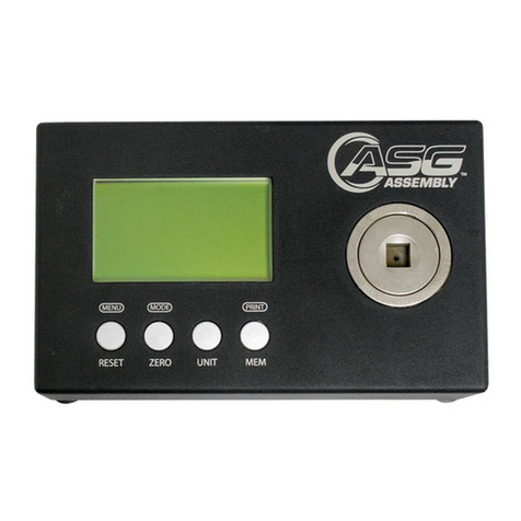
ASG DTT Series Use and care manual

2
TABLE OF CONTENTS PAGE
DTT Meter and LCDLayout 3
Button Functions 4
Menu Detail and Instructions 4-16
Main Menu 4
Menu 1, Zero Adjust 5
Menu 2, Setup 16
Menu 3, Memory 5,6
Menu 3, Memory, Memory Full Alert 6
Menu 4, Calibration 7,8,9,10
Menu 4, Calibration, System Password 8,9
Menu 4, Calibration, Change System Password 9,10
Menu 5, Communication 10,11,12, 13
Menu 6, Date & Time 13,14
Menu 6, Date & Time, Switch Time or Date on LCD 14
Menu 7, About 14
Setup Menu Detail and Instructions 15
Setup Menu 1, Measure Mode 16
Setup Menu 2, Measure Unit 17
Setup Menu 3, Auto Print 17
Setup Menu 4, Auto Memory 18
Setup Menu 5, Auto Reset 18,19
Setup Menu 6, Go- No Go 20,21,22
Setup Menu 7, Decimal Place 22
Setup Menu 8, Mfg. Settings 23
Setup Menu 8, Save Setup 15,16
System Overview 24
Port Settings for Auto Print 24
DTT Meter Specifications Sheet 25
Calibration Check Readings 26
Auto Reset and GO-NO GO setting levels 26
Torque Conversion Factors 27

3
DTT Meter Layout
During normal operation, the LCD display will show: The Measurement Mode in the upper left-hand corner
of the LCD. The Measurement Units in the upper right hand corner of the LCD. The Torque Reading in the
center of the LCD, The Current Time in the lower left hand corner of the LCD and the circle (or CW / CCW
arrow) showing the direction the torque was applied. This will be referred to as the operating display.
The ON/OFF SWITCH, CHARGER CONNECTOR and RS-232 PORT are on the left side of the meter. The
SERIAL NUMBER is on the back of the meter
Note, DTT-200 & DTT-500 have a mounting plate attached.
The LCD display pictured above id the default display. The DTT meter has various options described
herein. The LCD display below shows how it would look with all options enabled.
MODE Will show what mode the meter G/NG Will show if GO-NO GO is enabled.
is set in, either PEAK, FIRST PEAK or
TRACK MEMORY The letter A will appear in front of
number of readings to indicate that AUTO
TORQUE Will show the torque that was MEMORY is enabled.
applied.
SOUND A SPEAKER ICON will appear when
GOOD, NO GOOD When GO-NO GO sound has been enabled in G/NG
has been enabled the result will be
displayed as either good or no good UNITS The torque units selected will appear
based on the parameters set up. here.
TIME/DATE will show the date or time. DIRECTION ARROW. The “O” normally seen
Press the UP/DOWN buttons at the here will turn into either a clockwise arrow
same time to toggle between them. or a counterclockwise arrow to show the
direction in which the torque was applied.
AUTO Will be displayed when AUTO
RESET has been enabled.

4
Button Functions (left to right)
Button (#1) MENU/RESET/ESC
In normal operation, pressing the MENU/ RESET/ESC button resets the torque readings to zero in
either the PEAK or FIRST PEAK mode.
In TRACK MODE, pressing the MENU/RESET/ESC button takes you into the MAIN MENU. At any
other place in the menu this button acts as an ESCAPE button to take you back to the previous
screen.
Button (#2) DOWN/MODE
In normal operation, the DOWN/MODE button is used to change the MODE setting of the DTT
meter. Each time the button is pressed the mode will change from TRACK mode to PEAK, or from
PEAK to FIRST PEAK, or from FIRST PEAK to TRACK.
Within the menus this button is used to scroll DOWN to the next selection.
When inputting a number to set up the Date & Time, the Go, No-Go feature, the Auto Reset Mode
or calibration, pressing this button will decrease the number by 1 digit.
Button (#3) UP/UNIT
In normal operation, pressing this button changes the torque units of the meter. Pressing the
button will scroll through the 9 choices. Kgf-cm, gf-cm, Kgf-m, mN-m, cN-m, N-m, ozf-in, lbf-in,
lbf-ft, in this order. Do not attempt to back up by pressing the DOWN button, you will only
change the mode.
Within the menus this button is used to scroll UP to the next selection.
When inputting a number to set up the Date & Time, Go, No-Go feature, the Auto Reset Mode or
calibration, pressing this button will increase the number by 1 digit.
Button #4 MEM/ENTER
In normal operation, pressing the MEMORY button enters the torque reading into the DTT meters
memory.
In all other menus this button is used to ENTER the selection, or perform the action selected.
MENU DETAIL and INSTRUCTIONS
The DTT meter is menu driven. Please note that text actually seen on the LCD may have asterisks or other
characters used for spacing. When an asterisk is noted here it is used to call attention to a specific item
and is not part of the display. If confused or lost in a menu, press the ESCAPE button until you return to
the operating display and start over. When pressing the buttons to navigate in a menu or increase or
decrease a value, the button must be pressed and released once for each action. You will hear a beep
each time a button is pressed. The button may not be held down to increment faster.
Main Menu
To enter the Main Menu, press the MODE button until the unit is in TRACK mode, then press the
MENU button. You will see:
Main menu 1/2 There is only room on the LCD to display 8 lines of text. When a menu
1)Zero Adjust has more than 6 items, the “page number” will show to the right as
2)Setup either 1/2 or 2/2 depending which page is displayed.
3)Memory
4)Calibration
5)Communication
6)Date & Time
7)About
Use the UP or DOWN buttons to scroll to and select the desired menu and then press the ENTER
button to enter that menu or activate that function.

5
Menu 1) Zero Adjust
This operation cannot be performed with the charger connected.
Use if the DTT meter does not automatically zero when turned on, or if the LCD does not return
to zero when the RESET button is pressed.
To enter, select 1) Zero Adjust and press the ENTER button. You will see:
Zero Auto Adjust
Reading: 00.012
Key UP= Zero Adj
Enter= Save Zero
Unit= lbf.in*
*These units are specified in the Calibration Menu. These are the “System Units”. There
is no way to change the units here. The System Units are used in calibration and when
setting up the Auto Reset and Go/No Go functions. Do not confuse these units with
changing the default units in set up or during normal operations.
Press the UP button for automatic zero, this sets the unit’s auto adjust feature to zero. Press the
ENTER button to save the zero point in the system memory. You will see:
Zero Auto Adjust
System Save OK
Press any key
to continue
After pressing any button you have set the auto zero in the meter’s memory and you will again
see: Main menu 1/2
1) Zero Adjust
2) Setup
3) Memory
4) Calibration
5) Communication
6) Date & Time
7) About
Press ESCAPE to return to the normal operating display.
Menu 2) Setup
The SETUP MENU contains 8 sub menus used to activate the various functions available on the
DTT meter. Please go to the end of the MAIN MENU section on page 15 for details and
instructions for the features in the SETUP MENU
Menu 3) Memory
The DTT meter can store 200 torque readings in the memory. This menu allows you to view the
stored readings, clear the last reading or clear all readings in memory.
Select 3) MEMORY and press ENTER. You will see:
Data Memory Menu
1) View
2) Delete Last
3) Delete All
Select 1) View and press ENTER. You will see:
Memory 013/200 (this would indicate 13 readings in memory)
M013: (this is the number of the last reading in memory)
0004.78 lbf.in (this is the last reading entered)
20/02/04,11:20 (this is the date and time the data was entered)
M014: (this will be the number of the next reading)
_ _ _ _ _ _ _ _ (this is the space for the next reading)
_ _ _ _ _ _ _ _
Use the UP or DOWN buttons to scroll through and view the readings in memory.

6
Press ESCAPE. You will again see:
Data Memory Menu
1) View
2) Delete Last
3) Delete All
Select 2) Delete Last and press ENTER. You will see:
Delete Last?
1) Cancel
2) Accept
Select either 1) Cancel, not to delete the last reading, or 2) Accept to delete the last reading and
press ENTER You will again see:
Data Memory Menu
1) View
2) Delete Last
3) Delete All
If Cancel was selected, nothing changed. Select View again to see the same readings on the
screen as before. The last reading will be M013 etc.
If Accept was selected, reading M013 was deleted. Select View again to now see that the last
reading will be M012.
Select 3) Delete All and press ENTER. You will see:
Delete All?
1) Cancel
2) Accept
Select either Cancel, to not delete all the readings or Accept, to delete all of the reading and
press ENTER. You will again see:
Data Memory Menu
1) View
2) Delete Last
3) Delete All
If Cancel was selected, nothing changed. Select View again to see the same readings on the
screen as before. The last reading will be M013 etc.
If Accept was selected all readings were deleted. Select View again to now see that all readings
will be blank
Note! Whenever Delete is selected either to delete the last reading, or to delete all readings, the
UP or DOWN button must be used to select Accept. If ENTER is pressed inadvertently, without
selecting Accept, The action is cancelled, the previous menu appears and nothing was changed.
It is not possible to selectively delete readings in memory, either all readings or the last reading
may be deleted. If reading M013 is deleted, then the last reading will be M012. This “new” last
reading may then be deleted.
Delete Last reading is helpful if ENTER is inadvertently pressed with the display reading zero or
an unwanted reading is entered due to running the tool in reverse to unwind the fidaptor.
Press ESCAPE to return to the normal operating display.
Memory Full Alert
The DTT meter’s memory will hold only 200 torque readings. If an attempt is made to enter
reading #201 the meter will beep several times and the M200 (or A200) in the bottom right
hand corner of the LCD will flash FULL. Readings will have to be deleted before any more may
be entered.

7
Menu 4: Calibration
The Calibration menu is used when the DTT meter requires re-calibration. The System units are
selected here. ASG recommends annual re-calibration by qualified personnel. Re-calibration may
also be necessary if a check reveals that the DTT meter is out of spec. Calibration, or a
calibration check can only be performed with the DTT operating on battery power. Do not
calibrate the unit with the battery charger attached.
It is not necessary to be in the calibration menu to check the meter to see if it is in spec. Attach
the proper calibration arm, or wheel and hang enough weight to check the DTT meter at is
maximum torque capacity. Allow the system to stabilize. Check the reading on the LCD and
determine if it is within +-.2% of maximum capacity. (For a DTT-100 this will be +-.2 lbf.in, for
other models check page 26) Check the DTT meter at several other points to insure that the
meter is linear. The readings must be within +-.2 lbf.in of the actual torque applied.
If calibration is necessary make sure the DTT meter’s battery is charged. Turn the meter on and
let it warm up for 30 minutes. The meter cannot be calibrated with the battery charger attached.
The Calibration Menu is protected by a 4 digit password. The password is 9991
Select 4) Calibration and press ENTER. You will see:
System Password
Enter password
4 Digit
Password: 0
Use the UP or DOWN button to select the first digit and press ENTER. You will then see:
Password: *0
Each time you enter a number, the previous number will be replace with an *
Use the UP or DOWN button to select the second digit and press ENTER. You will then see:
Password: **0
Use the UP or DOWN button to select the third digit and press ENTER. You will then see:
Password: ***0
Use the UP or DOWN button to select the fourth digit and press ENTER. You will then see:
Calibration Menu
1) System Unit
2) CW Gain
3) CCW Gain
4) Set Password
5) Save Value
Select #1) System Unit and press ENTER. You will see:
Select Cal. Unit
1) kgf-cm
2) N-m
3) lbf-in
Note! These are the “System Units.” The System units may be changed without having to re-
calibrate the DTT meter. For initial calibration of a DTT meter, select the system units that match
the weights and arm that will be used to calibrate the DTT meter. This will also set the units
specified in the ZERO ADJUST, AUTO RESET and GO-NO GO functions.
Select the proper units and press ENTER. You will again see:
Calibration Menu
1) System Unit
2) CW Gain
3) CCW Gain
4) Set Password
5) Save Value

8
Select #2) CW Gain and press ENTER. You will see:
Adjust CW Gain
Reading : 000. 00
Gain : 000000
Up & Dnto Adjust
Enter to Accept
Unit = lbf-in.
Attach the calibration arm, or wheel, and hang the proper amount of weight to equal the
maximum torque of the unit in the clockwise direction. Allow the display to stabilize. If the
reading is off more than +-.2% of the Maximum torque of the DTT meter, In the case of a DTT-
100 this will be +-.2 lbf.in. see page 26 for other models,adjustment is needed. If the reading is
more than 100.2 lbf.in, or less than 99.8 lbf.in, use the UP or DOWN buttons to bring the reading
within that range. When the reading is within the allowable limit change the amount of weight
and repeat the process at a different torque reading. Check the readings at several other points
of the scale to be sure that the readings are within +-.2 lbf.in of the proper reading. ASG checks
4 points. After checking in the CW direction Press the ENTER button. You will again see:
Calibration Menu
1) System Unit
2) CW Gain
3) CCW Gain
4) Set Password
5) Save Value
Select #3) CCW gain and repeat the calibration procedure.
Press ENTER. You will again see:
Calibration Menu
1) System Unit
2) CW Gain
3) CCW Gain
4) Set Password
5) Save Value
Select #5) Save Value and press ENTER. You will see:
Calibration Save
1) Cancel
2) Accept
Select 1) Cancel and press ENTER. You will have changed nothing and you will again see:
Calibration Menu
1) System Unit
2) CW Gain
3) CCW Gain
4) Set Password
5) Save Value
Select 2) Save Value and press ENTER. You will again see:
Calibration Save
1) Cancel
2) Accept
Select 2) ACCEPT and press ENTER. You will see:
Calibration Save
System Save OK
Press any key
to continue

9
Press any button. You have saved the calibration information. You will again see:
Calibration Menu
1) System Unit
2) CW Gain
3) CCW Gain
4) Set Password
5) Save Value
Press ESCAPE. You will again see:
Main menu 1/2
1) Zero Adjust
2) Setup
3) Memory
4) Calibration
5) Communication
6) Date & Time
7) About
Press ESCAPE to return to the normal operating display.
CHANGE PASSWORD
To change the password select 4) Calibration and press ENTER. You will see.
System Password
Enter password
4 Digit
Password: 0
WARNING if you select a new password and lose it, or forget it, the DTT meter MUST be
returned to ASG to have the password reset.
Use the UP or DOWN button to select the first digit and press ENTER. You will then see:
Password: X0
Unlike when you enter the existing password, the numbers will remain on the LED as
you enter them.
Use the UP or DOWN button to select the second digit and press ENTER. You will then see:
Password: XX0
Use the UP or DOWN button to select the third digit and press ENTER. You will then see:
Password: XXX0
Use the UP or DOWN button to select the fourth digit. BEFORE YOU PRESS ENTER you will see:
Password: XXXX
This will be your new password. Write it in here _ _ _ _ to be sure you do not lose it. ASG
can reset the password to 9991 but the meter will have to be returned to ASG to
achieve this.
Press ENTER. You have changed the password. You will then again see:
Calibration Menu
1) System Unit
2) CW Gain
3) CCW Gain
4) Set Password
5) Save Value
To save this new password select 5) Save Value and press ENTER. You will see:
Calibration Save
1) Cancel
2) Accept

10
Select 2) ACCEPT and press ENTER. You will see:
Calibration Save
System Save OK
Press any key
to continue
Press any button. You have saved the new password. You will again see:
Calibration Menu
1) System Unit
2) CW Gain
3) CCW Gain
4) Set Password
5) Save Value
Press ESCAPE. You will again see:
Main menu 1/2
1) Zero Adjust
2) Setup
3) Memory
4) Calibration
5) Communication
6) Date & Time
7) About
Press ESCAPE to return to the normal operating display.
Menu 5: Communication
This function is used to download the stored torque readings in the DTT Meter’s memory to a PC,
via the RS-232 to USB Serial bridge cable, or the RS-232 to DB9 Serial cable supplied with the
DTT meter. Your computer must have the ASG Torque Memory Loader software, found on the
CD-ROM provided with your DTT meter, installed on your PC. NOTE You must also load the driver
(s) for the USB serial bridge cable if your PC does not recognize it. These drivers are on the CD
supplied with your unit.
To download data, connect the USB connector to a USB port on your PC, or the DB9 Serial plug
to a serial port on your PC. Connect the 6pin DINN connector to the RS-232 port marked on the
side of the DTT meter. This can be found on the side of the meter with the power switch. Make
sure the ASG Torque Memory Loader program is turned on in your computer.
Select 5) Communication and press ENTER. You will see:
________________
COMMUNICATION
MODE
______________
This will remain on the LCD until you have finished downloading the torque readings and press
any button.
With the DTT meter set in communication mode, start the ASG Memloader program in your
computer.
When the program has loaded the following screen will be seen on the monitor of your PC:

11
To begin to download the torque readings click on the icon shown below:
The following screen should now be seen on your PC.

12
The software will default to COM-1 (communication port 1) on your PC. If you have a conflict you
can change COM ports by clicking on CONFIG on the toolbar. You will see:
Use your mouse to select COM-2, COM-3, COM-4, COM-5 or COM-6
With the data now on your PC you may now save this file just as you would any other file. It will
have a *.trq extension. Determine how you want to label it then save it. You will be able to
reopen this file at any time.
It is not possible to do any manipulation of the data while it is in this software. You can choose to
export the data to a Microsoft Excel spreadsheet. To do this, click the “Excel” Icon. Just a
reminder, you must have Microsoft Excel on your computer.
An Excel spreadsheet will open on your PC that looks like this:

13
This file will be named “object.xls”. You can then save it with any name you choose.
Once the data is in the spreadsheet the math functions in Excel may be used to manipulate the
data to obtain statistics. You will have to determine how you want the data manipulated and what
statistics you want to keep.
After the data has been downloaded to your PC press any button on the DTT meter. You will
again see:
Main menu 1/2
1) Zero Adjust
2) Setup
3) Memory
4) Calibration
5) Communication
6) Date & Time
7) About
Press ESCAPE to return to the normal operating display.
Detach the RS-232 cable from the DTT meter. If the same PC will be used to download data each
time, the cable may be left attached to the USB port on that PC.
MENU 6: Date & Time
This function is used to setup Date and Time of the unit’s built in real time clock. The date is
expresses as DD/MM/YY. The time is expressed as HH:MM:SS and will be in 24hr format.
Select 6 ) Date & Time and press ENTER. You will see:
Date & Time Menu
1) Set Date
2) Set Time
Select 1) Set Date and press ENTER. You will see:
SET DATE___________
20/02/04
Up & Down to Adj
Enter for Next
Esc for Back
Press the UP button to increase the number, press the DOWN button to decrease the number.
When the correct day is showing press ENTER. You will now see:
SET DATE___________
20/02/04
Up & Down to Adj
Enter for Next
Esc for Back
Press the UP button to increase the number, press the DOWN button to decrease the number.
When the correct month is showing press ENTER. You will now see:
SET DATE___________
20/02/04
Up & Down to Adj
Enter for Next
Esc for Back
Press the UP button to increase the number, press the DOWN button to decrease the number.
When the correct year is showing press ENTER. You have successfully changed the date. You will
again see:
Date & Time Menu
1) Set Date
2) Set Time

14
Select 2) Set Time and press ENTER. You will see:
SET TIME___________
09/16/00
Up & Down to Adj
Enter for Next
Esc for Back
Press the UP button to increase the number, press the DOWN button to decrease the number.
When the correct hour is showing press ENTER. You will now see:
SET TIME___________
09/16/00
Up & Down to Adj
Enter for Next
Esc for Back
Press the UP button to increase the number, press the DOWN button to decrease the number.
When the correct minutes are showing press ENTER. You will now see:
SET TIME___________
09/16/00
Up & Down to Adj
Enter for Next
Esc for Back
Press the UP button to increase the number, press the DOWN button to decrease the number.
When the correct seconds are showing press ENTER. You have successfully changed the time.
You will again see:
Date & Time Menu
1) Set Date
2) Set Time
After the Date and Time have been successfully entered the ESCAPE button must be pressed to
return to the Main Menu. Press ESCAPE you will again see:
Main menu 1/2
1) Zero Adjust
2) Setup
3) Memory
4) Calibration
5) Communication
6) Date & Time
7) About
Switch Time or Date on the LCD
The time is the default setting showing on the lower left-hand corner of the LCD. To display the
date, press the UP and DOWN button at the same time while in the normal operating mode. The
date will now show in the lower left-hand corner. When the unit is turned off, it will again default
to show the time.
Press ESCAPE to return to the normal operating display
MENU 7: About
This menu shows the model number of the meter, the version number of the firmware and the
serial number of the main board & processor.
This firmware version should not be confused with the version of the ASG download software.
The serial number of the main board may or may not be the same as the physical serial found on
the back of the DTT meter.

15
Select 7) About and press ENTER. You will see:
____________________
TORQUE TESTER v4F
Model : DTT100
MB 0204
__________________
There is nothing here you can change. Pressing any button returns you to:
Main menu 1/2
1) Zero Adjust
2) Setup
3) Memory
4) Calibration
5) Communication
6) Date & Time
7) About
Press ESCAPE to return to the normal operating display.
This is the end of the Main Menu section. The next section is the detail and instructions for Menu
2, the Setup menu.
SETUP MENU DETAIL and INSTRUCTIONS
Menu 2) Setup (This is the #2 selection on the Main menu)
9) Save Setup
The Setup menu contains 9 sub menus. These submenus control the various optional functions
available, and determine the default settings for the DTT meter. As part of the default settings,
the function will be activated each time you turn the meter on for use.
To set anything up as part of the default settings you must save the setup. If a function is set
up and not saved, that function will not be activated the next time the meter is turned on.
Since Save Setup will be used to save each function, the procedure will be described first rather
than as part of each individual menu.
Select 2) Setup and press the ENTER button. You will see:
Setup menu 1/2 There is only room on the LCD to display 8 lines of text.
1)Zero Adjust If a menu has more than 6 items, the “page number” will the
2)Setup show to the either 1/2 or 2/2 depending which page is
3) Auto Print
4) Auto Memory
5) Auto Reset Mode
6) Go-No Go Mode
7) Decimal Place
8) Mfg. Setting
9) Save Setup
Select 8) Save Setup and press ENTER. You will see:
Setup Save?
1) Cancel
2) Accept
Select 2) Accept and press ENTER. You will see:
Setup Save ?____
System Save OK
Press any key
To Continue
The setup has been successfully saved. Pressing any button will bring you back to:

16
Setup Menu 1/2
1) Measure Mode
2) Measure Unit
3) Auto Print
4) Auto Memory
5) Auto Reset Mode
6) Go-No Go Mode
7) Decimal Place
8) Mfg. Setting
9) Save Setup
Note! Remember you have to change the mode to TRACK to enter the Main Menu. If you save
the setup without changing back to Peak or First peak, then TRACK mode will be set as the
default. With TRACK as the default mode pressing the RESET or ESCAPE button takes the meter
into the Main Menu. This could confuse an operator.
Press ESCAPE to return to the normal operating display.
SET UP MENU
1) Measure Mode
Changes the measurement mode of the DTT meter and sets the default mode when saved.
Select 1) Measure Mode and press ENTER. You will see:
Setup Mode
1) Track
2) Peak
3) First Peak
Track mode is used to set the operating display to show real time torque value readings. The
reading on the display will rise or fall as the torque rises or falls. This would be used when
checking the meter to see if it is in spec.
Peak mode is used to show the peak reading of the applied torque. This peak value will be held
on the display until the ESCAPE button is pressed or a higher torque is applied. If the AUTO
RESET function has been selected then the display will then show the next reading as it is
applied, as long as the next reading exceeds the threshold point programmed during set up.
First Peak mode is similar to peak mode, but this function will only detect the first torque
applied. The display will not change as more torque is applied or if another reading is attempted.
The RESET button will have to be pressed to set the display back to zero.
Use the UP or DOWN buttons to select your choice and press the ENTER button.
You have set the meter to the Mode of your choice and you will again see:
Setup Menu 1/2
1) Measure Mode
2) Measure Unit
3) Auto Print
4) Auto Memory
5) Auto Reset Mode
6) Go-No Go Mode
7) Decimal Place
8) Mfg. Setting
9) Save Setup
To avoid forgetting to reset to peak mode, save before exiting the setup menu.
Note! This procedure sets the default setting for the meter. While operating the meter, any Mode
may be selected at any time by pressing the MODE button. When the meter is turned off, then
turned back on it will default to the last mode saved.
Press ESCAPE to return to the normal operating display

17
2) Measure Unit
Sets the default torque units for the DTT meter. This should not be confused with changing the
units in normal operation with the UNIT button or setting the system units in the calibration
menu.
Select 2) Measure Unit and press ENTER. You will see:
Setup Unit 1/2
1) Kgf-cm.
2) gf-cm.
3) Kgf-m.
4) mN-m.
5) cN-m.
6) N-m. Note only the first 6 choices will show on the LCD.
7) ozf-in. Use the UP or DOWN buttons to scroll through the
8) lbf-in. rest.
9) lbf-ft.
Select your choice of units and press ENTER. You have set the torque units. You will again see:
Setup Menu 1/2
1) Measure Mode
2) Measure Unit
3) Auto Print
4) Auto Memory
5) Auto Reset Mode
6) Go-No Go Mode
7) Decimal Place
8) Mfg. Setting
9) Save Setup
Before you save the setup make sure you have reselected PEAK or FIRST PEAK. Follow the Save
Setup instructions.
Press ESCAPE to return to the normal operating display.
3) Auto Print
With Auto Print turned on, the torque data is automatically sent to the RS-232 port on the
meter in real time each time a reading is taken. It is not necessary to press any button. This
function will work only in PEAK MODE and only with the torque readings applied in the clockwise
direction. See page
Select 3) Auto Print and you will see:
Setup AutoPrint
1) OFF
2) Use AutoPrint
Select 2) Use Auto Print and press ENTER. Auto Print is activated and you will again see:
Setup Menu 1/2
1) Measure Mode
2) Measure Unit
3) Auto Print
4) Auto Memory
5) Auto Reset Mode
6) Go-No Go Mode
7) Decimal Place
8) Mfg. Setting
9) Save Setup
Before you save the setup make sure you have reselected PEAK or FIRST PEAK. Follow the Save
Setup instructions.

18
4) Auto Memory
With Auto Memory turned on, the torque reading is automatically entered into the DTT memory
each time a new reading is taken. It is not necessary to press the ENTER button each time. This
will function only in PEAK MODE and only with torque readings applied in the clockwise direction.
Select 3) Auto Memory and press ENTER. You will see:
Setup AutoMemory
1) OFF
2) Use AutoMemory
Select 2) Use Auto Memory and press ENTER. Auto Memory is activated and you will again see:
Setup Menu 1/2
1) Measure Mode
2) Measure Unit
3) Auto Print
4) Auto Memory
5) Auto Reset Mode
6) Go-No Go Mode
7) Decimal Place
8) Mfg. Setting
9) Save Setup
Before you save the setup make sure you have reselected PEAK as your default setting. Follow
the Save Setup instructions. In the bottom right hand corner of the LCD where it showed
“M013” indicating 13 readings in memory, “A013” will now be displayed. This indicates 13
readings in memory with Auto Memory activated.
To turn Auto Memory off, enter the Main Menu, select Set Up, select Auto Memory and select Off.
Press ENTER. Auto Memory is deactivated and you will again see:
Setup Menu 1/2
1) Measure Mode
2) Measure Unit
3) Auto Print
4) Auto Memory
5) Auto Reset Mode
6) Go-No Go Mode
7) Decimal Place
8) Mfg. Setting
9) Save Setup
Before you save the setup make sure you have reselected PEAK as your default setting. Follow
the Save Setup instructions. In the bottom right hand corner of the LCD where it showed “A013”
indicating 13 readings in memory with Auto Reset de-activated, “M013” will now be displayed
indicating 13 readings in memory with Auto Memory activated.
5) Auto Reset Mode
Auto Reset is used to automatically reset the meter and display the next torque reading without
having to press the RESET button each time to clear the previous reading. Auto reset can be
used in PEAK mode only. Auto Reset can be used with Auto Memory to automatically enter the
reading into memory and reset the reading.
If a high torque value is selected for the threshold, say 20 lbf.in, and a lower torque is applied
first, say 10 lbf in, the 10 lbf.in will be displayed on the LCD. If the next reading is 15 lbf.in it will
also be displayed. Until you reach the threshold the DTT meter acts as it does in peak mode. Any
reading higher than the previous reading will be displayed. A lower reading will not register. Once
the threshold has been reached any torque reading that is higher than the threshold will be
displayed whether it is higher than the previous reading or not.
Select 4) Auto Reset Mode and press ENTER. You will see:
Setup Auto Reset
1) OFF
2) Use Auto Reset

19
Select 2) Use Auto Reset and press ENTER. You will see:
AutoReset min 2%*
Enter Percent
of 100 lbf.in**
Old Data : 00%
Enter New : 00%
*This % number will depend on which model DTT meter is used. See page 26 for other
models. This will be a minimum % of the torque units shown. The torque units can not
be changed here. The torque units can only be changed in the calibration menu.
**This number is the maximum torque value of the meter. The maximum torque of the
DTT-100 is 100 lbf.in (See page 26 for other models) therefore, For the DTT-100 the
minimum threshold that can be set to act as the “trigger” to over write the existing
reading with the new reading is 2% of 100 lbf.in, or 2 lbf.in. Any %, from 2% to 99%,
can be selected, for the DTT -100, which would then represent 2 to 99lbf.in.
To set up the threshold to 15 lbf.in, on a DTT-100 you would use UP or DOWN to enter 15%. 15
lbf.in will be 15% of 100. Press UP or DOWN to change Enter New : 00to ENTER NEW : 10
You do not have to worry about which value will change. Only the zero underlined in the ENTER
NEW line will change. No other number will change until ENTER is pressed. After you change the
00 to 10 and press ENTER you will see:
AutoReset min 2%
Enter Percent
of 100 lbf.in
Old Data : 00%
Enter New : 10%
Use the UP or DOWN button to change Enter New : 10 to Enter New : 15 and press
ENTER. 15% has been set as the threshold. Auto Reset has been activated and you will again
see:
Before you save the setup make sure you have reselected PEAK as your default setting. Follow
the Save Setup instructions. The word “AUTO” will now show between the time and the memory
number at the bottom of the LCD when the unit is turned on.
To turn Auto Reset off, enter the main menu, select set up, select Auto Reset Mode and press
ENTER. You will see:
Setup Auto Reset
1) OFF
2) Use Auto Reset
Select 1) Off and press ENTER. Auto Reset has been de-activated and you will again see:
Setup Menu 1/2
1) Measure Mode
2) Measure Unit
3) Auto Print
4) Auto Memory
5) Auto Reset Mode
6) Go-No Go Mode
7) Decimal Place
8) Mfg. Setting
9) Save Setup
Before you save the setup make sure you have reselected PEAK as your default setting. Follow
the Save Setup instructions. The word “AUTO” will no longer show on the LCD in the normal
operating display.
Caution, If Auto Reset is set too low you could experience “kick back” in the
driver adaptor when the tool shuts off. This can cause erroneous low torque
readings. If you see what seems to be very low reading based upon the
torque the tool is set at, check the direction arrow on the LCD. If it shows
counter clockwise, set the threshold higher, closer to the torque setting of
the tool.

20
5) Go-No Go Mode
Go-No Go mode is used to set a range or “window” for acceptable torque readings. This can be
used only with the meter in PEAK or FIRST PEAK modes. When a torque falls within the range the
meter will show the word “GOOD!” on the LCD just above the time. Any torque reading outside
this range, higher or lower, will cause the LCD show message “NO GOOD!” This range can be
set between 2 and 99% of the maximum torque of the meter. There is also a sound option that
will cause the meter to “beep” when a reading is within the range.
Say you wish to test a number of hand torque drivers that are supposed to be set at 15 lbf.in.
You may say that as long as the driver is above 13 lbf.in but below 17 lbf.in the driver is
acceptable.
Select 5) Go-No Go and press ENTER. You will see:
Setup Go -NoGo
1) Set Lower Level
2) Set Upper Level
3) Set Sound
Select 1) Set Lower Level and press ENTER. You will see:
Set Lower Level
1) Off
2) Use Lower Level
Select 2) Use Lower Level and press ENTER. You will see:
Set Lower Level
Enter Percent
of 100 lbf.in*
Old Data : 00%
Enter New: 00
*This number is the maximum torque value of the meter. On a DTT-100 this is 100 lbf.in. The
minimum lower level that can be set up is 2%. 2% of 100 lbf.in will be 2 lbf.in. (See page 26 for
the min torque value for other models). Any number from 2 to 99 can be selected which would
then represent 2% to 99% of 100 lbf.in on a DTT-100, or 2 to 99 lbf.in.
To set up the lower level to 13 lbf.in, on a DTT-100, you would use UP or DOWN to enter 13%.
13 lbf.in will be 13% of 100. Use UP or DOWN to change Enter New : 00to ENTER NEW :
10. You do not have to worry about which value will change. Only the zero underlined in the
ENTER NEW line will change. No other number will change until ENTER is pressed. After you
change the 00 to 10 and press ENTER you will see:
Set Lower Level
Enter Percent
of 100 lbf.in
Old Data : 00%
Enter New: 10
Use the UP or DOWN button to change Enter New : 10 to Enter New : 13 and press
ENTER. 13% has been set as the lower level and you will again see:
Setup Go -NoGo
1) Set Lower Level
2) Set Upper Level
3) Set Sound
Select 2) Set Upper Level and press ENTER. You will see:
Set Upper Level
1) Off
2) Use Upper Level
Select 2) Use Upper Level and press ENTER. You will see:
Set Upper Level
Enter Percent
of 100 lbf.in*
Old Data : 00%
Enter New: 00
Other manuals for DTT Series
1
This manual suits for next models
7
Table of contents
Other ASG Test Equipment manuals
Popular Test Equipment manuals by other brands

UEi
UEi DT301 instruction manual

Covita
Covita Smokerlyzer Micro+ Use & Storage

Hioki
Hioki IM9202 instruction manual

Hioki
Hioki CLAMP ON LEAK HiTESTER 3283 instruction manual

Gossen MetraWatt
Gossen MetraWatt SECUTEST BASE quick start guide

Martindale Electric
Martindale Electric HPAT600/2 HANDYPAT instruction manual

shumatt
shumatt VP37 VE 37 RED4 instruction manual

Bosch
Bosch Denoxtronic 1.1 Product description

Delta United Instrument
Delta United Instrument DU-330 Series Operation manual

KYORITSU
KYORITSU 4116A Instruction manual and users guide

Bante Instruments
Bante Instruments PHscan30S instruction manual

BSS Audio
BSS Audio AR 130 manual