ASG, Division of Jergens, Inc.
15
7
0
0
S. Waterloo Road | Cleveland, OH 44110-3898 | Phone: (888) 486-6163 | Fax: (216) 481-4519 | Email: [email protected] | www.asg-jergens.comPage 2 of 23
Table of Contents
Service and Warranty ............................................................................................... 4
Overload Capacity Caution ...................................................................................... 4
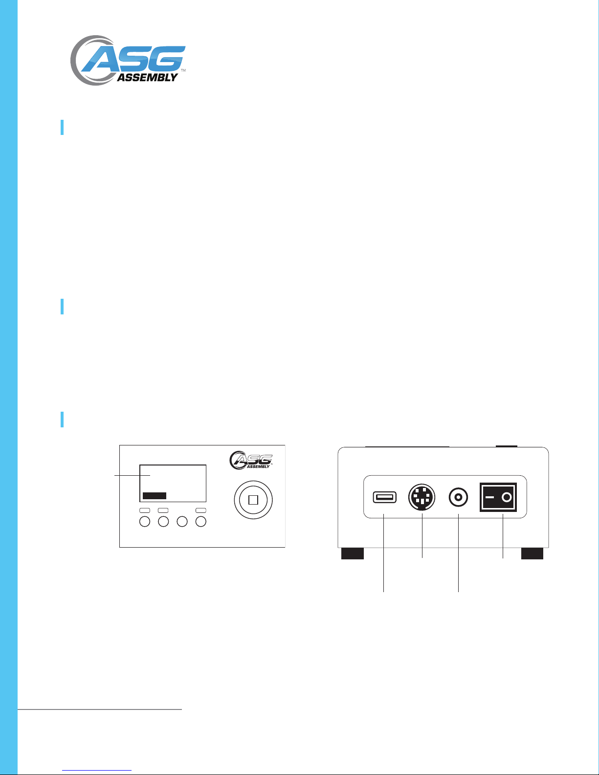
System Overview...................................................................................................... 4
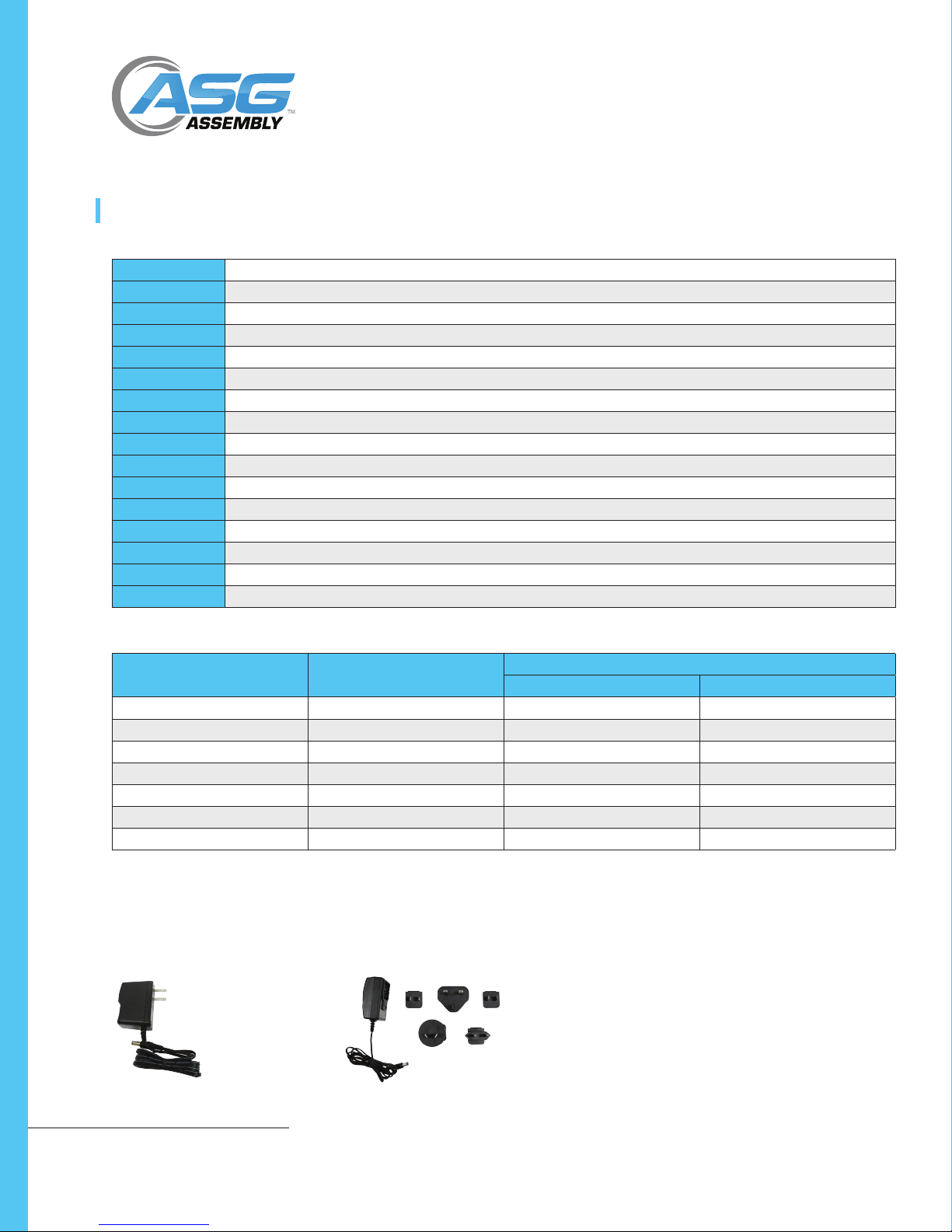
Battery Charger............................................................................................... 5
Standard Equipment ................................................................................................ 6
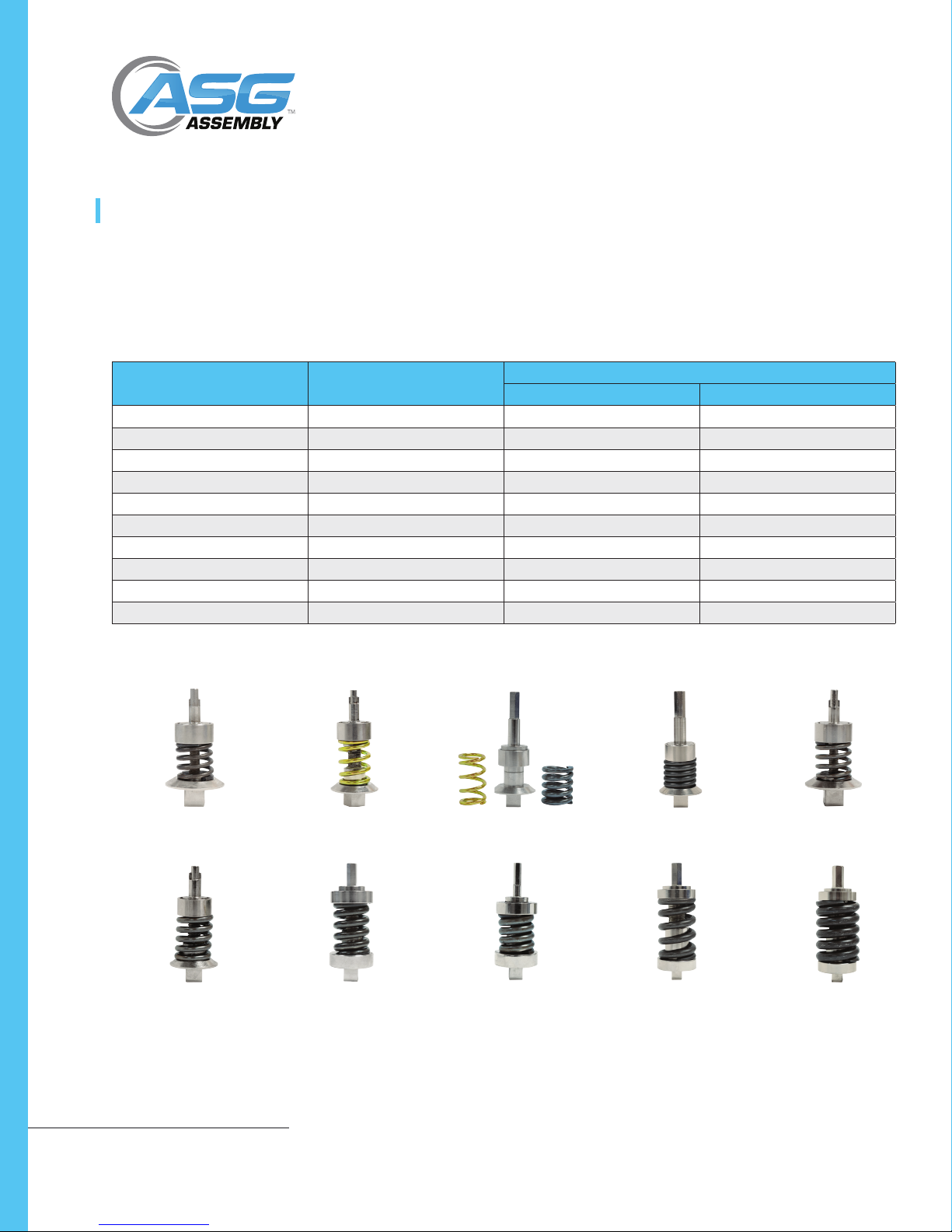
Instructions for Using the Rundown Adapter ........................................................... 7
Usage....................................................................................................................... 8
Procedure for Manual Torque Screwdrivers..................................................... 8
Procedure for Power Screwdrivers................................................................... 8
Battery Indicator ...................................................................................................... 9
Basic Function.......................................................................................................... 9
Display of Clockwise/Counter-Clockwise......................................................... 9
Zeroing the Tester.......................................................................................... 10
Changing the Unit of Measure...................................................................... 10
Changing the Mode of Measure ................................................................... 10
Backlit Display............................................................................................... 11
Saved Reading to Memory............................................................................ 11
Output Signal................................................................................................ 11
Main Menu ............................................................................................................ 11
Setting........................................................................................................... 12
Auto Reset .................................................................................................... 12
Pass-Fail ........................................................................................................ 13
Auto Memory................................................................................................ 14
Auto Print...................................................................................................... 14
Factory Reset................................................................................................. 15
Memory......................................................................................................... 15
View.............................................................................................................. 15
Delete Last .................................................................................................... 16
Delete All ...................................................................................................... 16
Upload All ..................................................................................................... 16
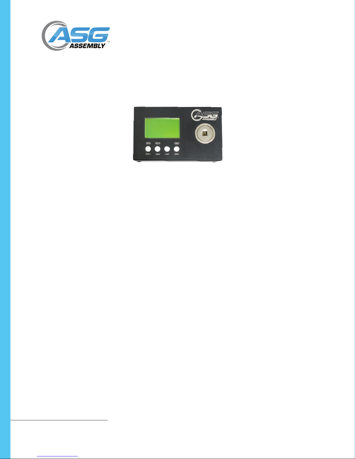
DTT Series Digital Torque Testers
User Manual