manuals.online logo
Brands
  1. Home
  2. •
  3. Brands
  4. •
  5. OWL
  6. •
  7. Test Equipment
  8. •
  9. OWL VOLT-1 User manual

OWL VOLT-1 User manual

Operations Guide
visual Optical Length Tester (VOLT)
Date: August 10, 2006
Version 1.3
VOLT
Operations Guide
Visual Optical Length Tester
Optical Wavelength Laboratories
e
T
h
s
W
e
i
i
s
r
e
o
t
C
a
h
r
o
o
i
c
b
e
a
L
i
n
h
O
t
g
p
n
t
e
i
l
c
e
a
l
v
F
a
i
b
W
e
l
r
a
c
i
T
t
e
p
s
t
O
OWL
5 Commonwealth Ave
Woburn, MA 01801
Phone 781-665-1400
Toll Free 1-800-517-8431
Visit us at www.TestEquipmentDepot.com
Unit 1 - Introduction
Description 1-1
General Features 1-1
Precautions 1-2
Required Accessories 1-2
Applications 1-2
Unit 2 - Operation
Fiber Length Measurement 2-1
Visual Fiber Identification 2-1
Visual Fault Location 2-2
Unit 3 - Appendices
Maintenance and Calibration Procedures 3-1
Specifications 3-1
Contact Information 3-1
Conversion Factors 3-2
Table of Contents
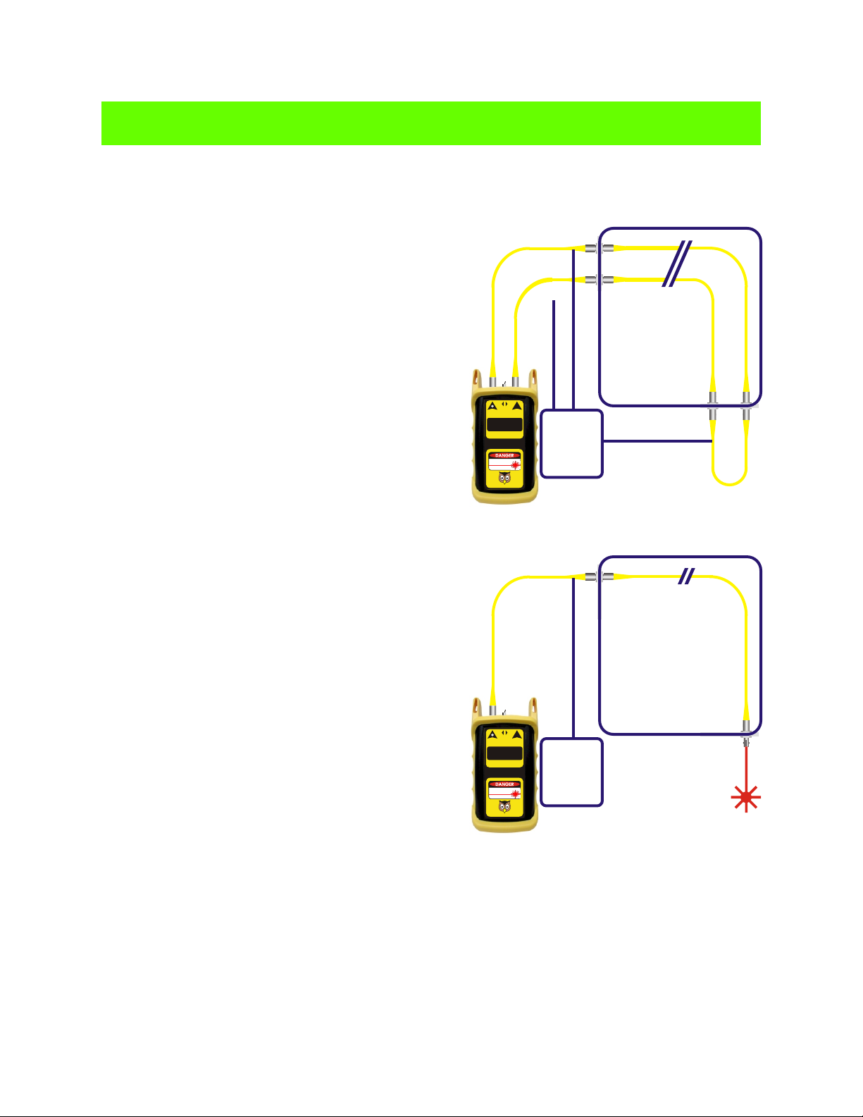
This manual describes the operation of the VOLT (visual Optical Length Tester). The VOLT is designed to
measure the length of singlemode and multimode cables. It uses a “round robin” technique for fiber
measurement; i.e. it loops back two fibers in the same fiber cable with a patch cord. The round trip time of the
optical pulse is converted to kilometers, then divided by two to give the length of the fiber cable. There is no
need to measure the length of every fiber; the length will be the same for all fibers in the cable, so this test only
needs to be run once for each cable. This technique allows the VOLT to be very accurate (up to ± 2.5 meters).
Many network cabling standards require the fiber cable length to be recorded along with attenuation
measurements. Optical measurement of fibers provides a quick and easy alternative to check the fiber jacket
for markings or estimating the length by using a measuring wheel, and often provides a greater degree of
accuracy.
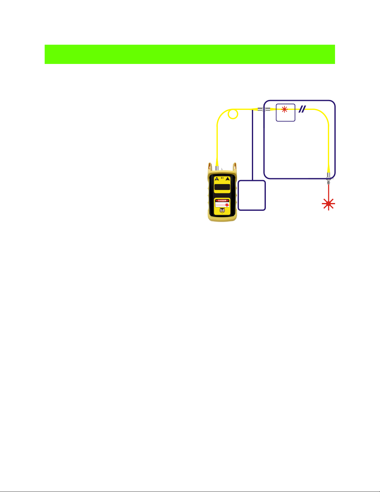
The visible red laser in the VOLT allows it to be used as a visual fiber identifier as well as a visual fault locator
(VFL).
NOTE: To avoid confusion, the VOLT is NOT designed to measure distance to a fault like an OTDR.
The VOLT is designed to measure the end-to-end length of a fiber cable. A pair of terminated fibers,
looped back at the far end of the cable, are required for end-to-end fiber cable length measurement.
Description
1-1
Introduction
UNIT 1
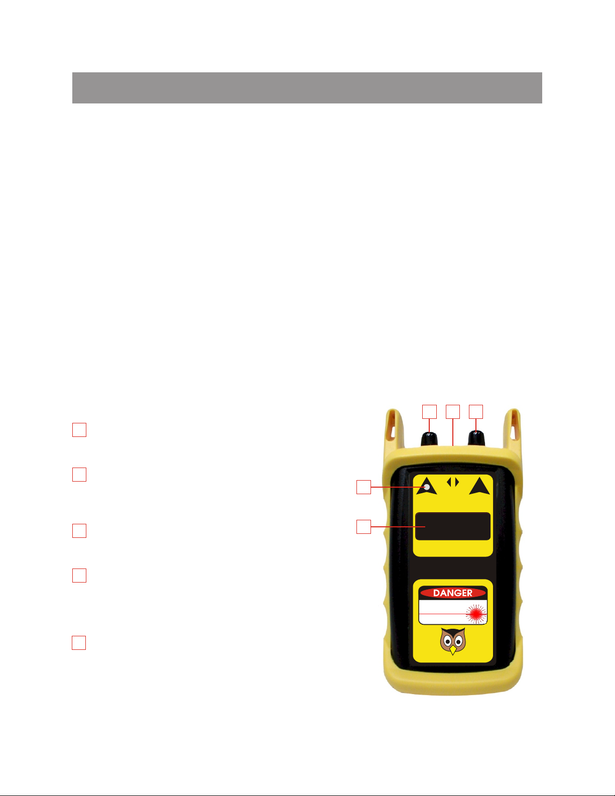
BRIGHT RED LASER TRANSMITTER - this ST
connector port houses a laser diode that emits bright red
visible light into an optical fiber.
CONTINUOUS WAVE/TEST SELECTOR SWITCH -
this 3-way switch selects between OFF (center), length
testing / fiber identification mode (right), and continuous
wave mode (left).
DETECTOR PORT - this ST connector port houses a
photodiode detector used to receive light from an optical
fiber.
POWER LED - this LED indicates that the tester is
powered on. During normal operation, if this LED is very
dim or is not lit, this indicates that the battery may not
have sufficient power for accurate testing, and should be
replaced.
LED DISPLAY - this 7-segment LED is used to display
the length of the fiber link in kilometers. If the display
shows all dashes, the VOLT is not receiving enough light
to make a measurement. This means that either the link
is either too long to be measured or there is a problem
with one of the fibers used for length measurement.
General Features
4
4
3
2
1
123
5
5
O
F
F
Input
SELECT
CW TEST
V.O.L.T.
Length in Kilometers
Optical Wavelength Laboratories
RADIATION
LASER
NEVER LOOK INTO ANY LIGHT SOURCE!
Output
Visual Optical Length Tester
1.250
1-2
Introduction
UNIT 1
Precautions
Safety. Extreme caution must be exercised when operating the VOLT. It produces an intense beam of visible
light that can cause permanent damage to the eye with prolonged exposure.
Operational. In order to insure accurate and reliable readings, it is vitally important to clean the ports on the
tester, as well as the ferrules on the patch cords, before each use. If dirt, dust, or oil are allowed to build up
inside the connector, the surface of the laser diode may become scratched, producing erroneous results.
Replace the dust caps on the tester ports and patch cords when not in use.
NEVER LOOK INTO A LIGHT SOURCE OR THE END OF A FIBER THAT MAY BE ENERGIZED BY A
SOURCE!
Required Accessories
Cleaning Supplies. Fiber ferrules, connector ports and bulkheads should be cleaned with 99% or better
isopropyl alcohol and a lint-free cloth. A can of compressed air should be available to dry off the ferrules, and
to blow dust from the connector ports and bulkheads.
Patch Cords. Two identical patch cords are required to connect the VOLT to the system under test, and a third
patch cord is required to loop back the two fibers being used for the test. The connector styles on the patch
cords must match the type on the VOLT and the type of the bulkheads in the system under test.
Applications
Fiber Length Measurement. The VOLT uses a “round robin” method of length measurement. This method
requires two fibers from the same fiber cable to be looped back at one end with a patch cord. Light is injected
into one of the fibers by the transmitter and is received by the detector connected to the other fiber. The round
trip travel time is converted into length in kilometers and divided by two to arrive at the length of the fiber cable.
It is not necessary to test each fiber for length; the length measurement applies to all fibers in the cable.
Visual Fiber Identification. The VOLT provides a flashing mode for easy visual fiber identification. Fibers are
identified by locating the fiber end with the flashing red light on the opposite end of the fiber cable. This is
useful for locating fibers that are marked incorrectly or not marked at all.
Visual Fault Location. In Continuous Wave Mode, a steady beam of ultra-bright red laser light is injected into
the fiber. If this light encounters a break or microbend in the fiber, the light will be redirected into the buffer.
This light will be visible through the fiber jacket, informing the user of a break or microbend in the fiber.
O
F
F
Input
SELECT
CW TEST
V.O.L.T.
Length in Kilometers
Optical Wavelength Laboratories
RADIATION
LASER
NEVER LOOK INTO ANY LIGHT SOURCE!
Output
Visual Optical Length Tester
- - - -
O
F
F
Input
SELECT
CW TEST
V.O.L.T.
Length in Kilometers
Optical Wavelength Laboratories
RADIATION
LASER
NEVER LOOK INTO ANY LIGHT SOURCE!
Output
Visual Optical Length Tester
1.250
Operation
UNIT 2
Fiber Length Measurement
1 - On one end of the fiber cable, loop back two of the
fibers with one of the patch cords.
2 - On the other end of the fiber cable, connect one patch
cord to each of the fibers being used for the test.
Connect the other end of the patch cords to the
receiver and transmitter ports on the VOLT. It does not
matter which patch cord connects to which fiber.
3 - Power on the VOLT into length test mode by flipping
the switch to TEST. In a few seconds, the display will
show the length of the fiber in kilometers. In the
example at right, the link is 1.250 kilometers.
NOTE: If the green indicator LED does not light up, this
means that the battery has insufficient power for a valid
test, and must be replaced before continuing.
Visual Fiber Identification
1 - Connect the VOLT to the fiber you are testing via a
patch cord as shown at right.
2 - Power ON the VOLT into fiber identification mode by
flipping the switch to TEST. This mode emits a flashing
beam of high-intensity red light into the fiber.
3 - Identify the fiber by looking for the flashing red light
emitting from the connector.
Fiber Length Measurement
Patch
Cords
Fiber
Link
2-1
Patch
Cord
Fiber
Link
Fiber Identification
O
F
F
Input
SELECT
CW TEST
V.O.L.T.
Length in Kilometers
Optical Wavelength Laboratories
RADIATION
LASER
NEVER LOOK INTO ANY LIGHT SOURCE!
Output
Visual Optical Length Tester
Operation
UNIT 2
Visual Fault Location
1 - Connect the VOLT to the fiber you are testing via a
patch cord as shown at right.
2 - Power ON the VOLT to visual fault location mode by
flipping the switch to CW. If there is a fault in the first few
meters of the fiber, red light should appear as a red glow
through the fiber jacket.
2-2
Patch
Cord
Fiber
Link
Visual Fault Location
Fault
Appendices
UNIT 3
3-1
Maintenance and Calibration Procedures
Specifications
Repair. Repair of this unit by unauthorized personnel is prohibited, and will void any warranty associated with
the unit.
Battery Replacement. The battery compartment is covered by a sliding plate on the back of the unit. One 9v
battery is required for operation.
Cleaning. For accurate readings, the optical connectors on the VOLT and the connectors on the patch cords
should be cleaned prior to attaching them to one another. Minimize dust and dirt buildup by replacing the dust
caps after each use.
Re-calibration. Re-calibration of the VOLT is not necessary.
Warranty. The VOLT comes standard with a two-year factory warranty, which covers manufacturer defects
and workmanship only.
Launch Method:
Output Power (into singlemode fiber):
Resolution:
Accuracy:
Measurement Range:
Battery Life:
Operating Temperature:
Storage Temperature:
Low Battery Indicator:
Connector Style:
Width:
Height:
Depth:
Weight (with battery):
Bright Red Laser
at least -2 dBm
up to 0.001 kilometers
± 2.5 meters
1.5 kilometers
10 hours
0 to 55° C
0 to 75° C
Yes
ST
2.75 inches
4.94 inches
1.28 inches
154 grams
1 kilometer
1 kilometer
1 kilometer
1000 meters
0.6214 miles
3281 feet
Distance in Kilometers
1.250
Here are some examples of converting the VOLT display into different units of
measurement. For these examples, let us assume a fiber length of 1.25
kilometers as shown by the display at right.
kilometers to meters
1.250 x 1000 meters = 1250 meters
kilometers to miles
1.250 x 0.6214 miles = 0.777 miles
kilometers to feet
1.250 x 3281 feet = 4101.25 feet
Appendices
UNIT 3
3-2
Conversion Factors
The VOLT displays fiber length in kilometers. At times it may be necessary to convert the fiber length to a
different unit of measurement. The table below provides conversion factors for various units of
measurement.
To calculate the units you need, multiply the number on the VOLT display by the conversion factor listed in the
table below:

Other manuals for VOLT-1

1

This manual suits for next models

1

Other OWL Test Equipment manuals

OWL Bolt User manual

OWL

OWL Bolt User manual

OWL 2 Series User manual

OWL

OWL 2 Series User manual

OWL ZOOM 2 Series User manual

OWL

OWL ZOOM 2 Series User manual

OWL Micro OWL 2 Series User manual

OWL

OWL Micro OWL 2 Series User manual

OWL WaveTester Series User manual

OWL

OWL WaveTester Series User manual

OWL Micro OWL 2 Series User manual

OWL

OWL Micro OWL 2 Series User manual

OWL ZOOM 2 Series User manual

OWL

OWL ZOOM 2 Series User manual

OWL 7V Series User manual

OWL

OWL 7V Series User manual

OWL ZOOM 2 Series User manual

OWL

OWL ZOOM 2 Series User manual

Popular Test Equipment manuals by other brands

PCWork PCW03A user manual

PCWork

PCWork PCW03A user manual

Industrial Test Systems Spa eXact EZ quick start guide

Industrial Test Systems

Industrial Test Systems Spa eXact EZ quick start guide

AutoWatch 720 TAB Operator instructions

AutoWatch

AutoWatch 720 TAB Operator instructions

Unit UT677A operating manual

Unit

Unit UT677A operating manual

Westward 1EKN5 Operating instructions and parts manual

Westward

Westward 1EKN5 Operating instructions and parts manual

HVTest HT5600 manual

HVTest

HVTest HT5600 manual

Additel 761A user manual

Additel

Additel 761A user manual

Martin Lishman Soil pH151 instructions

Martin Lishman

Martin Lishman Soil pH151 instructions

Gemini Tinytag TGE-0003 Technical manual

Gemini

Gemini Tinytag TGE-0003 Technical manual

Circassia NIOX VERO user manual

Circassia

Circassia NIOX VERO user manual

ELECTROMATIC Check Line DT-311A operating instructions

ELECTROMATIC

ELECTROMATIC Check Line DT-311A operating instructions

Salutron SRT5000 instruction manual

Salutron

Salutron SRT5000 instruction manual

TiePie Handyscope TP450 user manual

TiePie

TiePie Handyscope TP450 user manual

Beissbarth BD 6 Series Short operation manual

Beissbarth

Beissbarth BD 6 Series Short operation manual

SCHUNK GFT-X 270 operating manual

SCHUNK

SCHUNK GFT-X 270 operating manual

Megger OTS60SX/2 user guide

Megger

Megger OTS60SX/2 user guide

GDZX ZXHL-100P manual

GDZX

GDZX ZXHL-100P manual

Elenco Electronics DT-100 manual

Elenco Electronics

Elenco Electronics DT-100 manual

manuals.online logo
manuals.online logoBrands
  • About & Mission
  • Contact us
  • Privacy Policy
  • Terms and Conditions

Copyright 2025 Manuals.Online. All Rights Reserved.