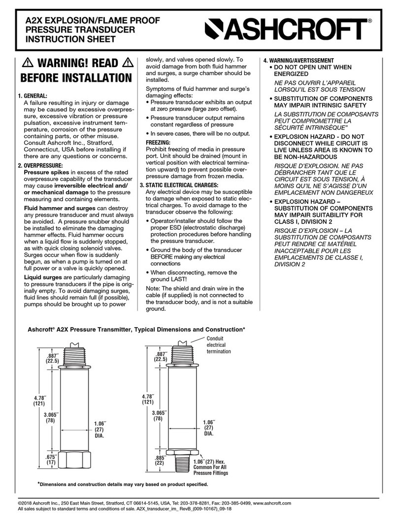
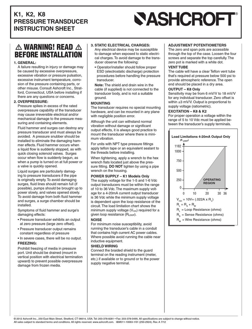
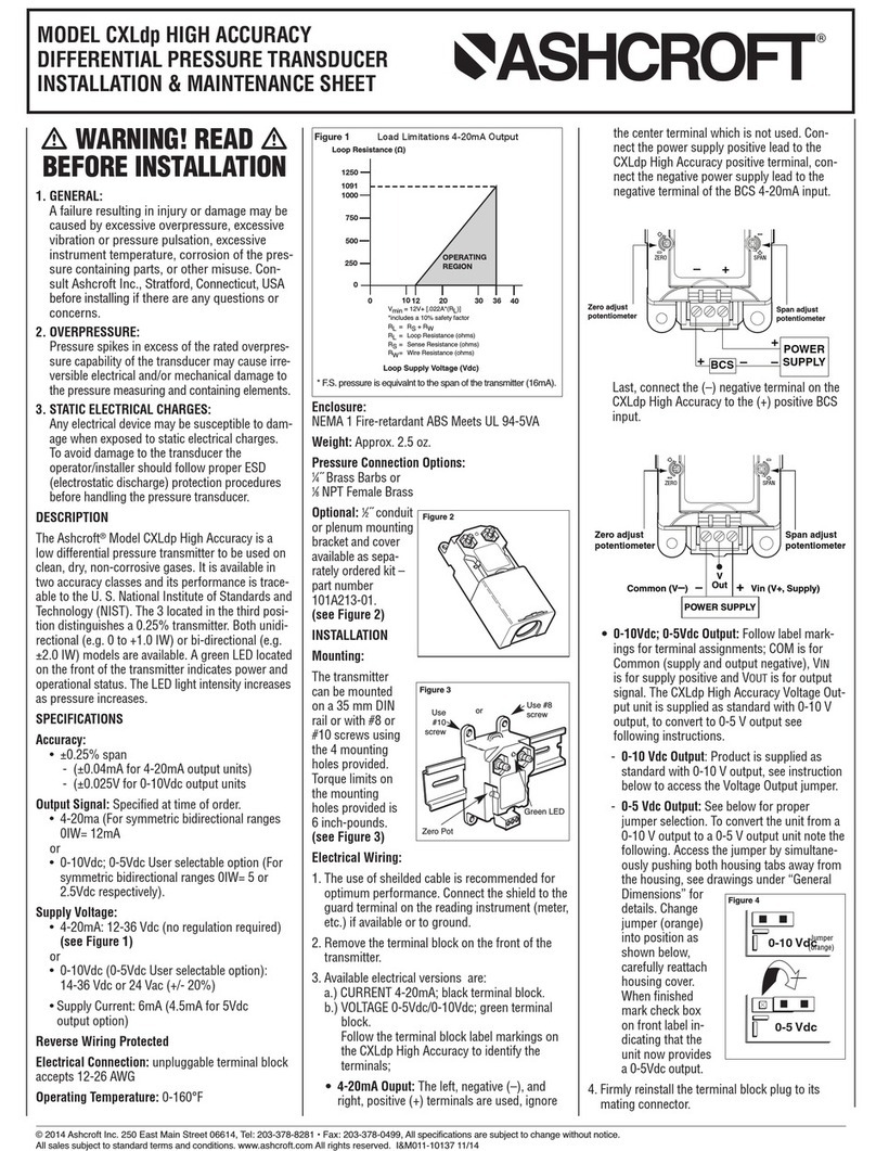
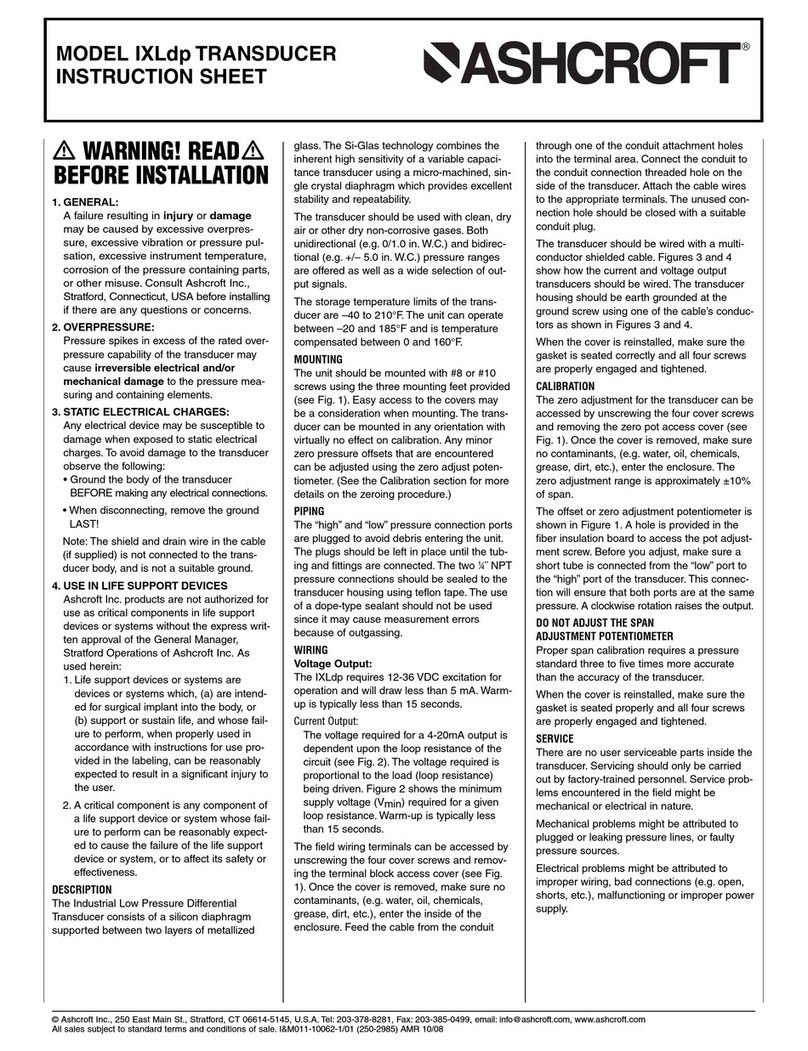
manuals.online logo
Brands
  1. Home
  2. •
  3. Brands
  4. •
  5. Ashcroft
  6. •
  7. Transducer
  8. •
  9. Ashcroft ZL91 Instruction Manual

Ashcroft ZL91 Instruction Manual

© 2021 Ashcroft Inc., 250 E. Main St., Stratford, CT 06614-5145, Tel: 203-378-8281, Fax: 203-385-0408, www.ashcroft.com
All sales subject to standard terms and conditions of sale. I&M011-10296_RevA_08-12-21
ZL91 FLUOROPOLYMER PRESSURE
TRANSDUCER INSTALLATION AND
MAINTENANCE SHEET
WARNING! READ
BEFORE INSTALLATION
1. GENERAL:
A failure resulting in injury or dam-
age may be caused by excessive
overpressure, excessive vibration
or pressure pulsation, excessive
instrument temperature, corrosion
of the pressure containing parts, or
other misuse. Consult Ashcroft Inc.,
Stratford, Connecticut, USA before
installing if there are any questions
or concerns.
2. OVERPRESSURE:
Pressure spikes in excess of the rated
overpressure capability of the trans-
ducer may cause irreversible elec-
trical and/or mechanical damage to
the pressure measuring and contain-
ing elements.
Fluid hammer and surges can de-
stroy any pressure transducer and
must always be avoided. A pressure
snubber should be installed to elimi-
nate the damaging hammer effects.
Fluid hammer occurs when a liquid
flow is suddenly stopped, as with quick
closing solenoid valves. Surges occur
when flow suddenly begins, as when
a pump is turned on at full power or a
valve is quickly opened.
Liquid surges are particularly damag-
ing to pressure transducers if the pipe
is originally empty. To avoid damaging
surges, fluid lines should remain full (if
possible), pumps should be brought
up to power slowly, and valves
opened slowly. To avoid damage from
both fluid hammer and surges, a surge
chamber should be installed.
Symptoms of fluid hammer and surge's
damaging effects:
• Pressure transducer exhibits an out-
put at zero pressure (large zero offset).
• Pressure transducer output remains
constant regardless of pressure
• In severe cases, there will be no output.
mm
FREEZING:
Prohibit freezing of media in pressure
port. Unit should be drained (mount
in vertical position with electrical ter-
mination upward) to prevent possible
overpressure damage from frozen media.
3. STATIC ELECTRICAL CHARGES:
Any electrical device may be sus-
ceptible to damage when exposed
to static electrical charges. To avoid
damage to the transducer observe the
following:
• Ground the body of the transducer
BEFORE making any electrical
connections.
• When disconnecting, remove the
ground LAST!
Note: The shield and drain wire in the
cable (if supplied) is not connected to
the transducer body, and is not a suit-
able ground.
Introduction
The ZL91 is a fluoropolymer pressure
transducer designed for ultrapure and
de-ionized water applications. It is con-
structed with PFA/PTFE wetted parts
that prevent metal ion elution and main-
tain the purity of your process fluid.
Mounting
When installing the ZL91, follow the
manufacturers recommended installa-
tion instruction for the specific compres-
sion fitting ordered.
When using the ZL91 with viscous
fluids, Ashcroft recommends that flow
through style transducers should be
mounted in the horizontal position to
reduce output errors.
Although the unit can withstand normal
vibration without damage or significant
output effects, it is always good practice
to mount the transducer where there is
minimum vibration.
Noise
For minimum noise susceptibility, avoid
running the transducer’s cable in a con-
duit that contains high current AC power
cables. Where possible avoid running
the cable near inductive equipment.
Shield Wiring - (Cable Termination Only)
Connect the braided shield to the guard
terminal on the reading instrument
(meter, etc.) if available or to ground or
to the power supply negative terminal.
Calibration - Zero Output Adjustment
ZL91 offers a zero point adjustment
potentiometer. To access the zero poten-
tiometer remove the black cap from the
top of the ZL91. Turn the potentiometer
using a standard screwdriver.
Instructions for calibration:
1. Power Unit
2. With no pressure applied to the sen-
sor, verify output.
3. If output has shifted from its ideal
value, (4mA for current output and
1.0 V for voltage output) turn poten-
tiometer until the output has reached
its ideal value.
Storage
The ZL91 should be stored in a dry,
cool and dust free environment.
Maintenance
In general, a periodic inspection of the
ZL91 should be performed at least twice
a year or as needed. This inspection
should include
A. Visual inspection
B. Check of the pressure inlets for cor-
rosion, clogging or leaking
C. Verify the output using calibrated
gauges
The ZL91 is not field repairable and should
be returned to Ashcroft for evaluation.
Wiring Diagrams
H
✔
HORIZONTAL VERTICAL
Potentiometer for Zero
point adjustment
3 Wire System (Voltage Output)
(dc Voltmeter)
Receiver
Power Source
12 to 24 Vdc
Power source (+) Red
Common Black
Output (+) White
ZL91
+
−
(dc Ammeter)
Receiver
24 Vdc ±10%
+ Red
– White
ZL91
+
+−
−
2 Wire System (Current Output)

© 2021 Ashcroft Inc., 250 E. Main St., Stratford, CT 06614-5145, Tel: 203-378-8281, Fax: 203-385-0408, www.ashcroft.com
All sales subject to standard terms and conditions of sale. I&M011-10296_RevA_08-12-21
ZL91 FLUOROPOLYMER PRESSURE
TRANSDUCER INSTALLATION AND
MAINTENANCE SHEET
Cable wiring color
Black
Red
White
Red
Output (+)
3wire2wire
(+)
White
(–)
Common
source
Power
Tube connection
PTFE(PFA)
PP
PP
60male screw
Flowell
S300male screw
Pillar
Flare nut(insert)
Entegris
20(A)nut(press fit)
Flowell
S300nut(press fit)
Pillar
Size
ZL91-17B
ZL91-16B
ZL91-14B,15B
ZL91-17A
ZL91-16A
ZL91-15A
ZL91-191,192,194,196
ZL91-181,182,184,186
ZL91-171,172,174,176
ZL91-161,162,164,166
ZL91-151,152,156
2.010.69
2.40
2.20
2.01
2.60
2.40
2.20
2.60
2.40
2.010.69
0.89
0.98
0.79
0.89
0.98
0.69
0.79
0.89
c
1.81
1.81
4.25
4.25
3.62
3.46
3.15
2.68
4.33
3.94
3.54
3.54
3.15 0.59
0.593.15
a
ZL91-141,144
b
Dimensions
Conecting port
O.D.1/4", I.D. 0.17˝
ZL91-1
 
Pillar S300male screw
Entegris Flaretek
Tube connection
Pillar S300nut(press fit)
Flowell 20(A)nut(press fit)
Pressure inlet
Flowell 60male screw
O.D.1/4", I.D. 5/32"
O.D.3/8", I.D. 1/4"
O.D.1/2", I.D. 3/8"
O.D.3/4", I.D. 5/8"
O.D.1", I.D. 7/8"
a
A
6
1
2
4
B
6
5
4
7
8
9
All dimensions are in inches
a (Size before construction)
1.18
78.74 (Standard)
1.57
1.97
Variable resister for
zero point adjustment
2ר 0.18
Shielded wire Air-release tube
Ø 0.19
Ø 1.81
0.39
b
c
1.02
White
(+)
2wire3wire
Output (+)
Red
White
Red
Black
Cable wiring color
PTFE(PFA)
PP
PP
Tube connection
size before construction
source
Power
(–)Common
S300nut(press fit)
Pillar
20(A)nut(press fit)
Flowell
Flare nut(insert)
Entegris
Dimensions
Size
O.D.1/2", I.D. 3/8"
O.D.3/8", I.D. 1/4"
O.D.1/4", I.D. 5/32"
O.D.1/4", I.D. 0.17˝
Conecting port
Entegris Flaretek
Flowell 20(A)nut(press fit)
Pillar S300nut(press fit)
Tube connection
Pressure inlet
ZL91-271,272,274,276
ZL91-261,262,264,266
ZL91-251,252,256
2.99
2.991.18
1.18
0.98 2.80
2.800.98
a
ZL91-241,244
b
6
5
4
7
6
1
2
4
ZL91-2
 
0.59
1.18
78.74 (Standard)
1.57
1.18
Variable resister for
zero point adjustment
2ר 0.17
Shielded wire Air-release tube
Ø 0.18
Ø 1.18
0.39
1.02
1.57
All dimensions are in inches
White
(+)
2wire3wire
Output (+)
Red
White
Red
Black
Cable wiring color
PTFE(PFA)
PP
PP
Tube connection
size before construction
source
Power
(–)Common
S300nut(press fit)
Pillar
20(A)nut(press fit)
Flowell
Flare nut(insert)
Entegris
Dimensions
Size
O.D.1/2", I.D. 3/8"
O.D.3/8", I.D. 1/4"
O.D.1/4", I.D. 5/32"
O.D.1/4", I.D. 0.17˝
Conecting port
Entegris Flaretek
Flowell 20(A)nut(press fit)
Pillar S300nut(press fit)
Tube connection
Pressure inlet
ZL91-271,272,274,276
ZL91-261,262,264,266
ZL91-251,252,256
2.99
2.991.18
1.18
0.98 2.80
2.800.98
a
ZL91-241,244
b
6
5
4
7
6
1
2
4
ZL91-2
 
0.59
1.18
78.74 (Standard)
1.57
1.18
Variable resister for
zero point adjustment
2ר 0.17
Shielded wire Air-release tube
Ø 0.18
Ø 1.18
0.39
1.02
1.57
All dimensions are in inches
ZL91 Tube ConnectionZL91 S300 Nut Connection

Other Ashcroft Transducer manuals

Ashcroft CXLdp Assembly instructions

Ashcroft

Ashcroft CXLdp Assembly instructions

Ashcroft IXLdp User manual

Ashcroft

Ashcroft IXLdp User manual

Ashcroft GC30 User manual

Ashcroft

Ashcroft GC30 User manual

Ashcroft k1 User manual

Ashcroft

Ashcroft k1 User manual

Ashcroft A2X User manual

Ashcroft

Ashcroft A2X User manual

Ashcroft IXLdp User manual

Ashcroft

Ashcroft IXLdp User manual

Ashcroft IXLdp User manual

Ashcroft

Ashcroft IXLdp User manual

Ashcroft KM15 User manual

Ashcroft

Ashcroft KM15 User manual

Ashcroft GC55 User manual

Ashcroft

Ashcroft GC55 User manual

Ashcroft CXLdp Instruction Manual

Ashcroft

Ashcroft CXLdp Instruction Manual

Ashcroft IXLdp User manual

Ashcroft

Ashcroft IXLdp User manual

Popular Transducer manuals by other brands

Humminbird XP 9 20 T quick start guide

Humminbird

Humminbird XP 9 20 T quick start guide

Clark Synthesis Prosound429 installation guide

Clark Synthesis

Clark Synthesis Prosound429 installation guide

Siemens Echomax XCT Series Operation manual

Siemens

Siemens Echomax XCT Series Operation manual

Simrad ES333-7CD -  REV A installation manual

Simrad

Simrad ES333-7CD - REV A installation manual

Siedle Novotechnik TP1 CANopen manual

Siedle

Siedle Novotechnik TP1 CANopen manual

Lumel VTR06 user manual

Lumel

Lumel VTR06 user manual

SSD ranger 5575 product manual

SSD

SSD ranger 5575 product manual

MKS Baratron 223B instruction manual

MKS

MKS Baratron 223B instruction manual

Veris E683 Series installation guide

Veris

Veris E683 Series installation guide

Simrad ES120-25X10 -  REV C datasheet

Simrad

Simrad ES120-25X10 - REV C datasheet

Desoutter Industrial Tools ART 4H5 User instructions

Desoutter

Desoutter Industrial Tools ART 4H5 User instructions

GE ApexPro T9 installation guide

GE

GE ApexPro T9 installation guide

Simrad ES38-12 - INSTALLATION REV A installation manual

Simrad

Simrad ES38-12 - INSTALLATION REV A installation manual

Balluff BTL6-V11V-M Series user guide

Balluff

Balluff BTL6-V11V-M Series user guide

Siemens 7XV5653-0BA00 manual

Siemens

Siemens 7XV5653-0BA00 manual

Daiichi Electronics FSPTT2-92A-33 instruction manual

Daiichi Electronics

Daiichi Electronics FSPTT2-92A-33 instruction manual

Siemens ST-H Series Operation manual

Siemens

Siemens ST-H Series Operation manual

SIAP+MICROS t018 TTP User manual and maintenance

SIAP+MICROS

SIAP+MICROS t018 TTP User manual and maintenance

manuals.online logo
manuals.online logoBrands
  • About & Mission
  • Contact us
  • Privacy Policy
  • Terms and Conditions

Copyright 2025 Manuals.Online. All Rights Reserved.