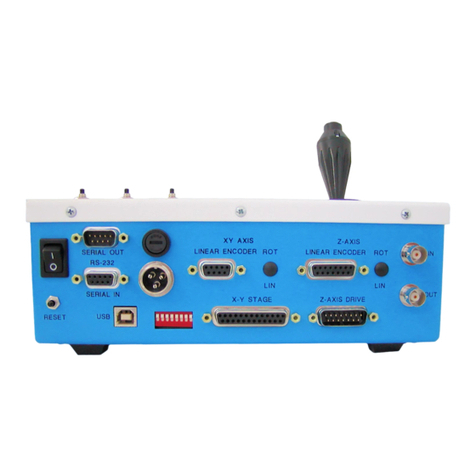
ASI Tiger TG-1000 User manual

2
Table of Contents
Electrical Characteristics ....................................................................3
WARNINGS ........................................................................................4
Description: .......................................................................................5
Tiger System: ...................................................................................................5
TIG/COM Card:....................................................................................................................................... 5
JOYSTICK / JOYPOD Input: ..................................................................................................................... 5
USB to PC Input:..................................................................................................................................... 5
RESET ..................................................................................................................................................... 5
Installation of Cables........................................................................................6
TG-1000 PROGRAMMING MANUAL....................................................8
Quick Reference –Main Operating Commands ................................................8
Quick Reference –Customization Commands ..................................................9
RS-232 Communication ..................................................................................10
Command ............................................................................................................................................ 10
Reply .................................................................................................................................................... 11
MS-2000 Reply Syntax ......................................................................................................................... 11
Examples.............................................................................................................................................. 11
Tiger Reply Syntax................................................................................................................................ 12
Error Codes ..........................................................................................................................................12
Query of Parameters ...........................................................................................................................13
TG-1000 and MS-2000’s instruction set differences ........................................13

3
Identifying Controller Configuration...............................................................15
Build Command ................................................................................................................................... 15
Tiger Banner.........................................................................................................................................17
A Note Regarding Units ..................................................................................18
TG-1000 Command Set...................................................................................18
Error Codes for TG-1000 Diagnostics ..............................................................68
Change log .....................................................................................................70
CLEANING & Maintenance: ............................................................................57
WARRANTY ....................................................................................................58

4
Electrical Characteristics
AC Input: 90-264 VAC, 3.3 A (peak), 50/60 Hz
AC In-rush Current (Cold Start): 77 A (maximum), at 240 VAC
Fuse Replacement: 2.0 A Fast Blow 250 VAC
(Spare fuse located in Power Jack on Back Panel)
Mains supply voltage fluctuations not to exceed 10% of the nominal voltage
Indoor use only

5
WARNINGS
1. Ensure power switch is in the OFF position before plugging in the power cord.
2. Do not unplug or plug-in devices / cables when power is on.
3. Do not remove the front or back panels; no user serviceable parts are inside.
4. Do not insert hand or non-isolated tools into Control Box even with power off. Stored
charge on capacitors could result in personal electrical shock or damaging of electrical
components if contact is made to internal circuit boards.
5. For indoor use only.
6. Do not position controller so that there is no access to the back mains supply input.
7. Protection provided by the equipment bay be impaired if the equipment is used in a
manner not specified by ASI.
8. In the event of device failure, contact ASI: (541) 461-8181
(800) 706-2284
International: 011-541-461-8181

6
Description:
Tiger System:
The Tiger system provides a case that houses multiple control cards and allows for future expansion. It
is available in 6, 8, or 16 slot configurations. The standard setup comes with +24, +5, & -5 VDC. The
power indicator shows that 5 VDC is on. The only card that comes standard with all Tiger systems is the
TIG/COM card.
TIG/COM Card:
The COM card is the base of the system. It provides communication to all cards installed into
the controller system via a backplane communication bus. The COM card actively monitors and
supervises all communications and inputs to the system and distributes the information to all
cards. Each card discerns what information to listen to and communicates with the COM card
to give responses on the USB port.
JOYSTICK / JOYPOD Input:
This port allows the attachment of the ASI JOYPOD unit. The joypod unit has an analog joystick,
multiple high resolution digital input knobs, as well as several switches and buttons. The COM card
monitors the input from the joypod and shares the information to all cards.Several serial USB port
commands can be used to set up which cards use the information and what it controls.
USB to PC Input:
This port allows the controller to be connected to a PC via USB which creates a virtual com port through
which high speed serial communication can be established. See the Tiger Programming manual for
more information.
COM Card
Power
Indicator
Reset
Joypod
Input
USB to PC
Input

7
RESET
The COM card also has a reset button which resets all the Cards installed as well as an input for the ASI.
See individual Control Card Manuals for details on each card type.
Installation of Cables
Plug the AC power cord into the rear of the controller. Attach the cable between the filterwheel and the
controller. Connect the serial cable between the computer and controller. WARNING: Ensure that the
power switch is in the “OFF” position while connecting or disconnecting connectors including the mains
power plug. Connecting and disconnecting with the power on can result in permanent damage to the
controller electronics.
The controller relies on proper orientation of the terminals on
the mains input plug. The ground terminal must be properly
earth grounded to provide safe protective grounding. Where
possible, correct connection of Neutral and Hot convention
should be followed.
Warning: Failure to follow Hot / Neutral conventions can result in failure of fuse shorting protection.
Danger: Failure to ground the ground terminal can result in failure of protection against electrical shock.
When setting up the controller several things should be taken into consideration. One, the controller
should not be setup in a location where access to the power cord is blocked. Although heat build up is
generally not an issue, the controller should be placed where it can get adequate ventilation to the
bottom air vents. The on/off power switch on the front of the controller should be easily accessible.
The controller should be close enough to the filter wheel / shutters that there is no strain on the
attachment cables.
Fuse
Ground
Neutral
Hot

11
Contents
TG-1000 PROGRAMMING MANUAL....................................................4
Quick Reference –Main Operating Commands ................................................4
Quick Reference –Customization Commands ..................................................4
RS-232 Communication ....................................................................................5
Command .............................................................................................................................................. 5
Reply ...................................................................................................................................................... 6
MS-2000 Reply Syntax ........................................................................................................................... 6
Examples................................................................................................................................................ 6
Tiger Reply Syntax.................................................................................................................................. 6
Error Codes ............................................................................................................................................ 7
Query of Parameters ............................................................................................................................. 7
TG-1000 and MS-2000’s instruction set differences ..........................................7
Identifying Controller Configuration.................................................................9
Build Command ..................................................................................................................................... 9
Tiger Banner.........................................................................................................................................10
A Note Regarding Units ..................................................................................11
TG-1000 Command Set...................................................................................11
Command: ACCEL ....................................................................................................................... 11
Command: AALIGN.....................................................................................................................12
Command: AFCONT (Requires Video Autofocus Hardware - See Autofocus Manual) .................12
Command: AFLIM (Requires Video Autofocus Hardware - See Autofocus Manual) ....................12
Command: AFOCUS (Requires Video Autofocus Hardware - See Autofocus Manual) ................... 12
Command: AFSET (Requires Video Autofocus Hardware - See Autofocus Manual) .............. 12

11
Command: AFMOVE (Requires Video Autofocus Hardware - See Autofocus Manual) ..................12
Command: AHOME (Requires ARRAY firmware module, not yet tested) ................................ 12
Command: AIJ (Requires ARRAY firmware module, not yet tested)........................................ 12
Command: ARRAY (Requires ARRAY firmware module, not yet tested) ..................................12
Command: AZERO .....................................................................................................................13
Command: BACKLASH ...............................................................................................................13
Command: BCUSTOM (Version 3+) .........................................................................................13
Command: BENABLE .................................................................................................................16
Command: BUILD ....................................................................................................................... 17
Command: CDATE ..................................................................................................................... 18
Command: CNTS........................................................................................................................ 18
Command: CUSTOMA ...............................................................................................................19
Command: CUSTOMB (PLANAR_CORRECTION firmware module required)............................. 23
Command: DACK ......................................................................................................................... 23
Command: DUMP.......................................................................................................................24
Command: ENSYNC ...................................................................................................................24
Command: EPOLARITY ...............................................................................................................24
Command: ERROR.....................................................................................................................25
Command: HALT........................................................................................................................ 25
Command: HERE........................................................................................................................25
Command: HOME.......................................................................................................................26
Command: INFO ........................................................................................................................27
Command: JOYSTICK ..................................................................................................................27
Command: JSSPD....................................................................................................................... 29
Command: KADC (For CRIFF and AF-DUAL Systems) ...............................................................29
Command: KD............................................................................................................................29

11
Command: KI .............................................................................................................................29
Command: KP .............................................................................................................................30
Command: LCD (not supported in TG-1000)............................................................................ 30
Command: LED (PWM_LED_DIM Firmware Required) .........................................................30
Command: LLADR......................................................................................................................30
Command: LOAD (RING BUFFER Firmware Module Required)................................................ 30
Command: LOCK (For CRIFF and AF-DUAL Systems)................................................................31
Command: LOCKRG (For CRIFF and AF-DUAL Systems)............................................................31
Command: MAINTAIN............................................................................................................... 31
Command: MOTCTRL ................................................................................................................32
Command: MOVE......................................................................................................................32
Command: MOVREL ..................................................................................................................33
Command: PCROS .....................................................................................................................33
Command: MULTIMV................................................................................................................34
Command: PEDAL (Requires Foot Pedal Hardware/Firmware) ................................................. 35
Command: RBMODE (RING BUFFER Firmware Module Required)........................................... 35
Command: RDADC.....................................................................................................................37
Command: RDSBYTE.................................................................................................................. 37
Command: RDSTAT ................................................................................................................... 38
Command: RELOCK (For CRIFF and AF-DUAL Systems).............................................................38
Command: RESET ...................................................................................................................... 38
Command: RTIME...................................................................................................................... 39
Command: RUNAWAY............................................................................................................... 39
Command: SAVESET ..................................................................................................................39
Command: SAVEPOS .................................................................................................................40
Command: SCAN (SCAN firmware required)............................................................................ 40

11
Command: SCANR (SCAN firmware required) ........................................................................... 40
Command: SCANV (SCAN firmware required) .......................................................................... 41
Command: SECURE (special hardware and U_SERVO_LK firmware module needed)............. 41
Command: SETHOME................................................................................................................ 42
Command: SETLOW................................................................................................................... 42
Command: SETUP...................................................................................................................... 42
Command: SPEED......................................................................................................................44
Command: SPIN......................................................................................................................... 44
Command: STATUS.................................................................................................................... 44
Command: STOPBITS (not supported in TG-1000).................................................................... 45
Command: TTL (only partly implemented in TG-1000)............................................................. 45
Command: UM ..........................................................................................................................47
Command: UNITS (not supported in TG-1000) ......................................................................... 47
Command: UNLOCK (For CRIFF or AF-DUAL Systems) ..............................................................47
Command: VB (Z and F arguments only for TG-1000) ..............................................................47
Command: VECTOR ................................................................................................................... 48
Command: VERSION.................................................................................................................. 48
Command: WAIT ....................................................................................................................... 48
Command: WHERE .................................................................................................................... 48
Command: WHO (TG-1000 v1.6+)............................................................................................ 49
Command: WRDAC (not supported on TG-1000) .....................................................................49
Command: ZERO ....................................................................................................................... 49
Command: Z2B .......................................................................................................................... 50
Command: ZF (requires ZFLOCK module) ................................................................................50
Command: ZS ............................................................................................................................50
Error Codes for TG-1000 Diagnostics ..............................................................52

11
TG-1000 PROGRAMMING MANUAL
The following section describes the RS-232 serial command set that the TG-1000 controller uses when
communicating with a host computer. It closely follows the command set for the MS-2000. If you don’t
need to know everything, just use the quick reference below to get started. Details of each command,
including examples, follow.
Quick Reference –Main Operating Commands
Command
Shortcut
Description
<DEL> , <BS>
Abort current command and flush input buffer
HALT
\
Halts all moves being executed
HERE
H
Writes a position to specified axis position buffer
HOME
!
Moves specified axes to physical limit switches
INFO
I
Returns a screen full of information about specified axis
MOTCTRL
MC
Enables/disables motor control for specified axis
MOVE
M
Writes a position to an axis target buffer
MOVREL
R
Writes a relative position to specified axis target buffer
RDSBYTE
RB
Returns a status byte for specified axis
RDSTAT
RS
Same as RDSBYTE, in decimal ASCII format
RESET
~
Resets the controller
SPEED
S
Sets the maximum velocity/speed of specified axis
SPIN
@
Causes specified axis to spin motor at given DAC rate
STATUS
/
Returns B-Busy, N-Not Busy
WHERE
W
Returns current position of specified axis
WHO
WHO
Prints list of cards with address and firmware information
ZERO
Z
Sets all axes to zero position (same as HERE <axis>=0 for all axes)

11
Quick Reference –Customization Commands
These commands support setup parameters. In most cases, these commands would be used only once
after the unit is powered up.
Command
Shortcut
Description
ACCEL
AC
Changes/Displays ramp time in milliseconds
BACKLASH
B
Changes axis backlash correction motion constant
BENABLE
BE
Enables/Disables buttons
ERROR
E
Changes/ Displays max position error allowable before the controller will
start re-correcting position.
JOYSTICK
J
Enables/Disables/Assigns manual control input for an axis
JSSPD
JS
Sets/Displays % Max speed for joystick ranges
MAINTAIN
MA
Makes axis hold its position indefinitely.
PCROS
PC
Changes/Displays position error at which controller considers a move to
be complete
SAVESET
SS Z
Saves current set-up parameters to FLASH memory.
SETLOW
SL
Sets/Displays lower firmware limit switch for an axis
SETUP
SH
Sets/Displays upper firmware limit switch for an axis

11
RS-232 Communication
The TG-1000 utilizes an RS-232 serial link to connect with any computer with an RS-232 serial port in
order to utilize all of the controller’s abilities. The current setup for the TG-1000 serial link is: 115200
baud, no parity, eight data bits, one stop bit, and no flow control (115200: 8 : N : 1 : None). This serial
control feature can be accessed through terminal programs such as TeraTerm, and HyperTerminal.
Software such as LabView can be used to send serial commands. Finally, high-level microscope control
software (e.g. Micro-manager, Molecular Devices’ Metamorph, Nikon Elements) uses serial commands
to communicate with the controller.
Command
The controller’s instruction set is implemented using the following format:
COMMAND X=?????? Y=?????? Z=?????? <Carriage Return>
The COMMAND is a string of ASCII characters such as MOVE or HOME, which must be followed by a
space. All commands are case-insensitive. Many commands have abbreviated versions that help cut
down on typing time and serial bus traffic.
Next are the axis parameters. (Bracketed “[ ]” parameters are optional.) The axis name is given,
followed immediately by an equal sign and the axis parameter value. Each axis must be separated from
the one before by one blank space. One or more axes may be specified on a single command line. An
axis symbol typed without an “=“ assignment is often assumed to mean “=0”, but that behavior isn’t
guaranteed in general (it does, however, work for the commonly-used MOVE and MOVREL commands).
Sometimes the command format may not require a parameter value (e.g., INFO X). Commands will
accept integer or decimal numbers; internal truncation or rounding will occur if fractional decimals are
of no meaning to the command.
axis or [axis] is the placeholder for the axis name, which is a single character. All 26 alphabet
characters A-Z can be used as axis names, and the special character * means “all axes” (not including
filterwheels). For example, X and Y are typically used for a sample translation stage, Z and F are
commonly used for focus axes, and A-D are the default letters for scanner axes. Filterwheels are
designated by numbers, TG-1000 can accommodate up to 10 wheels numbered 0-9.
When [Addr#] appears in the format, then the intended card address must be prepended to the
serial command, as the command is Card-Addressed.
“…” indicates more arguments can be sent with the same command.
All commands are completed with a Carriage Return (ASCII hex code: 0D). The controllers receive ASCII
characters one at a time and place them into their memory buffer. With the exception of single hex

11
code commands like the tilde (~), the controller will not process a command in the memory buffer until
the Carriage Return (<CR>) has been received.1
Reply
Upon receiving a Carriage Return <CR>, the TG-1000 will process the command stored in its command
buffer, clear the command buffer, and return a reply.
The TG-1000 has two reply syntaxes; the active one is set using the VB F command. The default syntax
is backwards compatible with the MS-2000 controller, including all the quirks and inconsistencies
between commands. The Tiger syntax is more self-consistent and in some cases more explanatory (e.g.
with WHERE), but is not backwards compatible. Choice of reply syntax is completely arbitrary and does
not affect operation.
MS-2000 Reply Syntax
When a command is recognized, the controller will send back a colon ‘:’ (hex code: 3A) to show that it is
processing the command. When processing of the command is complete, an answer is returned with
any requested information, typically beginning with the letter A. In some cases, the answer part of the
reply is delayed until the completion of the command. The reply is terminated by a carriage return and
a linefeed character (<CR><LF>). In the examples below, the <CR> and <CR> <LF> are implied.
This programming manual gives examples in the MS-2000 reply syntax unless otherwise specified.
Examples
(Typed commands are in THIS TYPEFACE; computer replies are in THIS TYPEFACE.)
MOVE X=1234 Z=1234.5
:A
MOVE X Y Z
:A
WHERE X
:A 0
MOVE X=4 Y=3 Z=1.5
:A
WHERE X Y Z
:A 4 3 1.5
WHERE Z Y X
:A 4 3 1.5
1ASI’s Control Character Bracketed Command Set, e.g., <Ctrl G><Ctrl H>, cause the memory command buffer to be emptied. This
allows the daisy-chaining of other peripherals, such as ASI’s SC-2 shutter controller, on the RS-232 line without causing unrecognized command
errors to be reported back by the TG-1000 and MS-2000. [does this apply to TG-1000?]

11
Tiger Reply Syntax
In the Tiger syntax no :A is sent back. Furthermore, whenever an axis position or command value is
returned (i.e. whenever the command is a query), the axis letter is always specified. Consequently,
when no information needs to be sent back and there is no error the controller simply replies with
<CR><LF> only.
The above examples in Tiger reply syntax are as follows:
MOVE X=1234 Z=1234.5
MOVE X Y Z
WHERE X
X=0
MOVE X=4 Y=3 Z=1.5
WHERE X Y Z
X=4 Y=3 Z=1.5
WHERE Z Y X
X=4 Y=3 Z=1.5
Error Codes
When a command is received that the TG-1000 cannot interpret, for one reason or another, an error
message is returned in the following format:
:N<error code>
The error codes are as follows:
:N-1 Unknown Command (Not Issued in TG-1000)
:N-2 Unrecognized Axis Parameter (valid axes are dependent on the controller)
:N-3 Missing parameters (command received requires an axis parameter such as x=1234)
:N-4 Parameter Out of Range
:N-5 Operation failed
:N-6 Undefined Error (command is incorrect, but for none of the above reasons)
:N-7 Invalid card address
:N-8..:N-10 Reserved

11
:N-11..:N-20 Reserved for filterwheel
:N-21 Serial Command halted by the HALT command
:N-30..:N-39 Reserved
Query of Parameters
Most commands used to set parameter values can be queried for the current values using the question-
mark syntax:
CMND X? Y? Z? F?
The controller will respond with CMND’s current settings, e.g.
:A X=0 Y=1 Z=10 F=2
This feature is most useful when using a terminal program to change controller parameters to verify that
you have made the changes that you think you did, or to check present settings.
TG-1000 and MS-2000’s instruction set differences
This section is intended to quickly bring the users up to speed on the major differences in the serial
commands between TG-1000 and MS-2000 controller.
Where possible the TG-1000 commands were kept close to the MS-2000 controller commands.
The Tiger reply syntax, described above, was added to Tiger starting in COMM card firmware v1.92.
Commands where the axis letter is specified work just like MS-2000, e.g. MOVE, MOVREL, and WHERE.
For example, X and Y axis reside on card with address “1”, and Z resides on card with address “2”. When
M X=## Y=### Z=### is issued the COMM card in TG-1000 controller parses the command, and
redirects the command to the appropriate card automatically. These commands are called Axis-Specific
Commands. A card address should not be specified with an Axis-Specific command, otherwise
undefined behavior may result from any mismatch between the address specified and the card with
the axis as determined by the COMM card.
The TG-1000 is able to support multiple add-ons like CRISP and Piezo stages whereas MS-2000 was only
able to support one, so we were forced to alter the command set to handle commands which are
intended for a certain card but do not contain the axis name. In those cases, the user must specify
which card the command is intended for, and the COMM card will relay the command appropriately.
For example, the SS Z command saves the settings into non-volatile memory, but the user may not
want all the settings on all the cards to be saved. For the TG-1000 the user has to add the card address
in front of the command to make it work. For example, if the card that drives XY axis has the address
“1”, to only save setting on this card user should issue 1SS Z. These commands are called Card-
Addressed Commands.2
2Previously Card-addressed commands they were called “Non-Addressed Commands,” referring to the

11
Importantly, for Card-Addressed Commands the setting applies to all axes on the card. For example, the
ring buffer delay can be set independently for the XY stage on one card and a piezo stage on a different
card. However, if a card contains more than one independent axis (e.g. a ZF card for two linear stages,
or a Micro mirror card for 2 scanners) then the same setting applies to all axes. Continuing our example,
the ring buffer on the ZF card would control both Z and F axes (though one of these axes could be
disconnected from the ring buffer) so Z and F could not have separate ring buffer delay times.
Various methods of determining the address of a specific card are given below.
A third category is Broadcast commands, like STATUS, HALT, RESET, and ZERO. They are routed to
all cards in a TG-1000 system by default, just like the MS-2000. However, in most cases they can also be
directed at a single card by simply adding the card address, so they could be considered as special type
of Card-Addressed Commands sent to all cards if an address is not specified.
A final category includes commands that default to a particular card, though they can be addressed to
specific cards as well. There are sub-categories of commands sent to the COMM card unless otherwise
specified (e.g. BUILD and WHO), commands sent to whatever card has the X axis or else all the stage
cards if the X axis doesn’t exist (e.g. JSSPD and LED), and commands sent to whatever card has the Z
axis or all the stage cards if the Z axis doesn’t exist (e.g. most CRISP and autofocus commands). These
sub-categories may be referred to as Comm-Default, Stage-Default, and Focus-Default commands
respectively.
Beginning with COMM card firmware version 3.10 a special axis letter * was added. When this
character is specified in an Axis-specific command then it applies to all the axes in the controller. For
instance, all axes can be moved to zero position using M *=0.3The * axis letter can also be combined
with card addressing to apply the command to all the axes on the same card, e.g. 3M *=0 will move
all axes on card address 3 to their zero position, and 3! * will home all axes on card 3.
How does the user find out a card address? When the TG-1000 is turned on or when WHO serial
command is issued, the controller prints out card address, axis names, firmware version and firmware
build date of all the cards installed in the system (see section Tiger Banner below for more details). Also,
more complete information about the cards and corresponding axes can be accessed using the BUILD
Xcommand which is described in the section Build Command below.
As an illustrative example, the controller may have the following configuration as reported on startup:
................................................................
At 30: Comm v1.5 TIGER_COMM May 07 2013:15:42:05
At 31: X:XYMotor,Y:XYMotor v2.4 STD_XY Jun 11 2013:17:00:12
fact that the command itself does not carry address information and thus it needed to be separately
specified.
3Actually the =0 can be omitted, since numeric arguments for MOVE default to 0.

11
At 32: Z:Piezo v2.4 ADEPT_PIEZO Jun 11 2013:17:05:00
Joystick ready.
System ready.
The card addresses are shown in ASCII code. At 31 indicates a card with X and Y axes has the address
“1” (ASCII code of 1 is 31).
To save settings in non volatile memory: 1SS Z (Card-Addressed)
To print its error dump buffer: 1DU Y (Card-Addressed)
To move X and Y axis: M X=### Y=### (Axis-Specific)
Similarly the card with Z axis has address “2” (ASCII code of 2 is 32).
To move Z axis: M Z=### (Axis-Specific)
To issue pzinfo command on this card: 2PZINFO (Card-Addressed)
To put in closed loop external input mode: 2PZ Z=1 (Card-Addressed)
To save settings into non-volatile memory: 2SS Z (Card-Addressed)
To run short calibration on the piezo: 2PZC (Card-Addressed)
Table 1 TG-1000 addresses
Addressee
Usage
Value
TG-1000 Comm
Hard coded, re-assignable
0x30 (‘0’)
Stage/ FW/Shutter
Unique Address
0x31 to 0x39, then 0x81 to
0xF5
Stage Broadcast
Recognized by all stage controllers
0xF6
Filterwheel Broadcast
Recognized by all FW controllers
0xF7
Shutter Broadcast
Recognized by all shutter controllers
0xF8
LCD Broadcast
Recognized by all LCD controllers
0xF9
Broadcast
Recognized by all cards
0xFD
Broadcast except
Comm
Recognized by all cards except TG-1000
Comm
0xFE
Table of contents
Other ASI Controllers manuals