manuals.online logo
Brands
  1. Home
  2. •
  3. Brands
  4. •
  5. Barco
  6. •
  7. Controllers
  8. •
  9. Barco ScreenPRO II User manual

Barco ScreenPRO II User manual

System Setup
Ethernet Port
Connect to Ethernet Switch on an isolated
network. Used for communications with
devices such as video routers, matrix
switchers, BlendPRO-II and ScreenPRO-II.
Also used for downloading code.
Ext Comm Port
For serial communications
with external devices such
as routers.
Quick Start Guide
Visibly yours
Barco Media and Entertainment
11101 Trade Center Drive
Rancho Cordova, CA
95670 • USA
Phone:
Fax:
Technical Support:
Websites:
+1 (916) 859-2500
+1 (916) 859-2515
+1 (866) 374-7878
www.folsom.com
www.events.barco.com
P/N 26-0505004-00, Rev A
ID Setup and Remote Enable — Set up your
individual ScreenPRO-II IDs, and enable remote
control on each ScreenPRO-II.
Before you begin, ensure that your system is properly
cabled. Use the sample charts on the back of this
guide, or refer to Chapter 3 in the User’s Guide.
Tally Connector
Requires optional Tally Board.
Connect to 8 external devices for
relay closure control. Refer to
Appendix A for connector pinouts.
Memory Card Slot
Store and recall system configurations
using customer supplied Flash Memory
Card (minimum size: 512 MB)
KEYBOARD TALLY
MEMORY CARD
EXT COMM
CONSOLE ETHERNET
T250V 2A FUSE
CAUTION: FOR CONTINUED PROTECTION
AGAINST RISK OF FIRE, REPLACE ONLY
WITH SAME TYPE AND RATING OF FUSE
Keyboard Port
Requires optional Tally Board.
Connect to customer supplied
PS-2 keyboard for entering
names and values.
AC
Connect to AC
power source.
Console Port
For serial communications
and downloading code.
1
System Power Up — Power up the entire system,
and download code (if required).
2
Return to Factory Default — Perform a complete
factory reset on all devices. This procedure resets all
router tables and source mappings.
3
Touch Screen Calibration — Calibrate the
Controller’s Touch Screen display.
4
Restore from Flash Memory Card — If you backed
up to Flash Memory, restore the configuration at this
point. No further setup steps are necessary.
5Programming EDID — For your background and DSK
sources, program EDID to ensure proper
communications to your PCs at the preferred resolution.
6
Standard Destination Setup — Set up your single
screen destinations (maximum 4) and/or your
widescreen destination (maximum 1).
7
Router Setup — Set up your system’s routing
switcher(s), including type, communications, output
patching, and designating Aux outputs.
8
Aux Destination Setup — Set up your system’s
Auxiliary destinations, including Aux, ImagePRO Aux
and ScreenPRO-II Aux destinations as required.
9
Input Patching — Associate (patch) specific router
inputs to specific source buttons on the Controller.
Assign tally connections as desired.
10
Output Format Setup — Configure the output format
for each ScreenPRO-II in your system to the native
resolution of the display or projector.
11
Genlock Setup — Set up Genlock for each destination
on the Output Menu. For a widescreen destination,
verify all BlendPRO-II “widescreen lock” connections.
12 Sync Setup — Set up sync parameters for the monitors
and projectors connected to the system.
13
Projector Setup — Set up your projectors for both
single screen and widescreen destinations.
14
Background Setup — Set up the two background
sources. Remember (on ScreenPRO-II) that BG/DSK
input B is shared between DSK and Background B.
15
Input Setup — Set up your system’s inputs. For
widescreen configurations only, adjust each input’s
phase and color balance at the output of BlendPRO-II.
16
DSK Setup — Set up the DSK as a DVI source or a
frame grab. Remember (on ScreenPRO-II) that BG/DSK
input B is shared between DSK and Background B.
17
LOGO Setup — Set up the LOGO as “black” or a frame
grab.
18
Save the Setup — From the Home Menu, press SAVE
to save the state of the Controller in non-volatile
memory.
19
Backup to Flash Memory Card — Back up your
system configuration to a customer-supplied Flash
Memory Card.
20
System setup is comprised of 20 sequences,
each of which includes many steps. For
error-free installation, always refer to the
associated section in Chapter 5 of the User’s Guide.
The circled sequence numbers are identical.
Layer Functions Section
Source Crop
Top
Left Bottom
Right
Reset Fine
Adjust
ADJUSTMENT PANEL
LIGHT
WIPE MIX
TRANSITIONS
CUT AUTO
TRANS
BG
ABG
BDSK LOGO
Split
LAYER
ALAYER
B
Program
Clear
Layer
PIP KEY Full
Screen Clone Swap
Z-Order Move
Setup Move Mix
Source Swap Toggle Freeze
LAYER FUNCTIONS
Change
active layer
to a PIP
Take active
layer to full
screen
Copy layer to
opposite screen
(widescreen only)
Set up a
“Move” on
active layer
Co-locate
both PIPs
(Split is Off)
Toggle
sources with
each transition
Change
active layer
to a Key
Change visual
layer priority
(Split mode only)
Pend “Move”
on the
active layer
Independently
locate PIPs
(Split is Off)
Freeze the
active layer
on Pgm, Pvw
Source Selection Bus
Joystick Section Destination / Aux Bus
Transition Section Layer Control Section
1
92
10 3
11 4
12 5
13 6
14 7
15 8
16 SHIFT SDI
1SDI
2
SOURCE SELECTION
Program
1 2 3 4 DEST
AUX
DESTINATIONS / AUX
ALL
Red LEDs
Solid: Source is on Program, associated destination is enabled
Blinking: Split is Off. Layer is on Program, opposite Layer on Preview
Source Selection Bus
Blinking: Source on Preview, blinking layer active for modification
Solid: Source on Preview, layer not active for modification
Each button is an input that
can be assigned to a PIP,
Key or Aux destination
Press to
access
sources 9-16
SDI buttons only
active when internal
routing enabled
Connect to
low voltage
“script” light.
Control
“script” light
brightness.
Adjust the selected PIP or Key. X-Axis
(left/right), Y-Axis (up/down), Z-Axis
(size). Z-Axis also adjusts value of
highlighted parameter on Touch Screen.
Crop bottom
and right
edges
Crop
boundaries
of PIP or Key
Adjust
source within
PIP or Key
Crop top and
left edges
Reset the
current effect
to default Increase
precision of
Joystick range
Press to select all
destinations. Double-
punch to turn all off.
Switch between standard and
Aux destinations. When lit, Aux
destinations can be selected.
Press 1-4 to enable one destination, press
two (or more) simultaneously to enable a
group. All selections mutually exclusive.
• Destination/Aux bus is one bus — not
two separate and independent buses.
• Source selections apply to all
enabled buses only
• Transitions will only be performed if the
desired destinations are enabled
T-Bar
Manually
transition sources
to/from Program,
based on current
transition type.
Select wipe as
the current
transition type
Select mix as
the current
transition type
Instantly cut
images from
Preview to
Program
Transition automatically
from Preview to Program.
Use Effects Menu to set
transition parameters.
Red LEDs
Indicate layers
on Program
Select unscaled
background Aor B
on Preview. BG B
and DSK are
mutually exclusive.
Select scaled
layer Aor Bon
Preview, to
assign as
PIP or Key
Select unscaled
DSK on
Preview
Select unscaled
LOGO on
Preview
Change
between Split
and Mix modes
Select any combination of
layers on Preview:
•Blinking: Layer is
selected and active
for adjustment
•Solid: Layer is
selected on Preview,
but is not active for
adjustment
Press to remove
active (blinking)
layer from Preview
3 4
5 6
7 8
WIPE and MIX effects can
be assigned on a per
destination basis, and
performed simultaneously.
Presets SectionTouch Screen Menu Section
V Position
V Size < 58.9% > 452
H
O
M
EN
A
V
PIP ADJUSTMENT
B
O
R
D
R
H Size < 37.3% > 674
70
A
D
J
TRACK SIZE
S
H
D
O
W
E
F
X
Move Rate [ 2.0 ]
Key Frame Effect [ LINEAR ]
H Position -34
--------------------------------
OPERATION:
JOY Z TO SIZE, X Y TO POSITION
1
1 2 3 4 5 6 Learn Delete Next Previous Page
PRESETS
Page
Four ways to access a function or a menu:
• Touch a button on the Touch Screen
• Press the Softkey adjacent to a label
• Use NAV to move the highlight, then ADJ
• Touch a line to move the highlight, then ADJ
1
Softkeys
Softkey labels (when
present) appear on the
Touch Screen
NAV
Move the highlight up
and down, or adjust the
labeled parameter
ADJ
Adjust the
highlighted parameter
Red LED
When lit, indicates
current “page” of Presets
Press to recall a Controller
setup (a “Preset”) to
Preview. Each button
represents a single “look”
Hold and
press 1-6 to
delete Preset
Hold and
press 1-6 to
select page
Jump to next
or previous
valid Preset
Hold and
press 1-6 to
store Preset
Touch Screen Menu Section
Used for system configuration,
setup and operational adjustments,
such as PIPs and Keys.
Presets Section
Stores and recalls Controller
setups. 36 Presets are available —
6 pages of 6 Presets each. 2
1
Layer Functions Section
When a layer is active, buttons in
this section apply, enabling you to
change the layer’s mode and
adjust the source.
3
Source Selection Bus
Selects the sources that are
routed to PIPs and Keys. Buttons
are provided for both analog and
SDI sources.
4
Joystick Section
Includes a 3-axis Joystick and
dedicated buttons that enable you
to adjust PIPs, Keys and many
additional system parameters.
5
Destination / Aux Bus
Routes signals to one or more
destinations, such as projectors and
Aux monitors. Four standard and
four Aux destinations are provided.
6
Transition Section
Enables you to select a transition
type, and perform a Preview-to-
Program transition. Use the T-Bar
for manually mixing sources.
7
Layer Control Section
Controls the overall “look” on
Preview and Program. Selects
the layer(s) that will transition
to or from Program.
8
1 2
MatrixPRO RGBHV Router
ScreenPRO-II #2
ScreenPRO-II #1
ImagePRO
Aux Destination 2
PresentationPRO-II
Aux Destination 1
ScreenPRO-II Controller
Ethernet Switch
(Local Network Only)
Single Screen Destinations
ScreenPRO-II
BlendPRO-II
Ethernet Switch
BlendPRO-II
ScreenPRO-II #2
ScreenPRO-II #1
ScreenPRO-II Controller
MatrixPRO HD-SDI Router
ImagePRO
PresentationPRO-II
Widescreen Destination
ScreenPRO-II Controller User’s Guide
Terminated
Un-terminated
In
Loop
Un-terminated
In
Loop
Un-terminated
Sample System — External Routing Sample System — Internal Routing
PC1: Background (DVI)
PC2: DSK (DVI)
Preview
Left Preview
Right
Program
Left Program
Right
GENLOCK WIDESCREEN LOCK
IN OUT
PC1: Background (DVI)
PC2: DSK (DVI)
Preview
Left Preview
Right
Program
Left Program
Right
Camera
MAC PC
Analog DA
Digital DA
DVD or VTR
Server or
D-VTR
Widescreen Lock Connections
ID
#1
ID
#2
ID
#3
ID
#4
In
Loop Widescreen Lock
(Required) Genlock
(Optional)
IN LOOP
GENLOCK
Termination
BlendPRO-II
Rear
Chassis
ScreenPRO-II
Rear
Chassis
Breakout Cables for Analog Inputs
Breakout Cable
Wire Color Comp
Video S-Video
(Y/C) YUV
(YPbPr) RGB
Sync on Green RGB
Comp Sync RGB
Separate H V
R
G
B
H Sync
V Sync
(Chrom) (Pr)
(Lum) (Lum)
(Pb)
For complete details on all installation, setup, configuration and operations procedures, please refer to
the ScreenPRO-II Controller User’s Guide.
P/N 26-0505004-00, Rev A
Aux Destination 1
Aux Destination 2
(Local Network Only)

Other Barco Controllers manuals

Barco Sedomat 1800 User manual

Barco

Barco Sedomat 1800 User manual

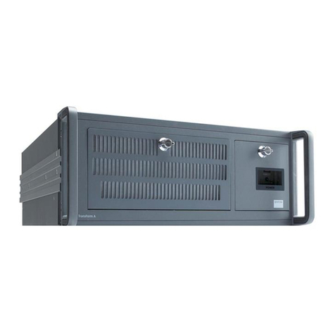
Barco TransForm A User manual

Barco

Barco TransForm A User manual

Barco Sedomat 600 User manual

Barco

Barco Sedomat 600 User manual

Barco EC Series Installation and operating manual

Barco

Barco EC Series Installation and operating manual

Barco EC Series Installation and operating manual

Barco

Barco EC Series Installation and operating manual

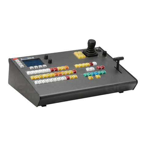
Barco ScreenPRO-II User manual

Barco

Barco ScreenPRO-II User manual

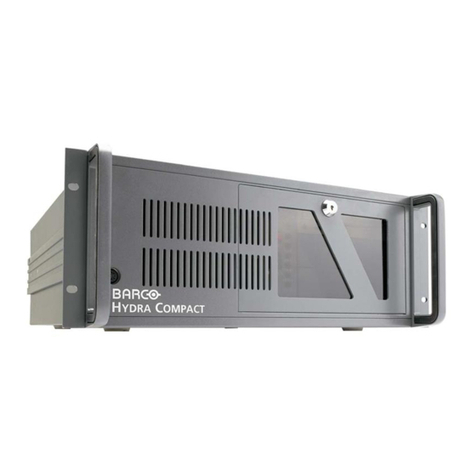
Barco Hydra Compact User manual

Barco

Barco Hydra Compact User manual

Barco MXRT-1450 User manual

Barco

Barco MXRT-1450 User manual

Barco P110 User manual

Barco

Barco P110 User manual

Barco Sedomat 1500 User manual

Barco

Barco Sedomat 1500 User manual

Barco BarcoMed 2MP2HX User manual

Barco

Barco BarcoMed 2MP2HX User manual

Barco KVD User manual

Barco

Barco KVD User manual

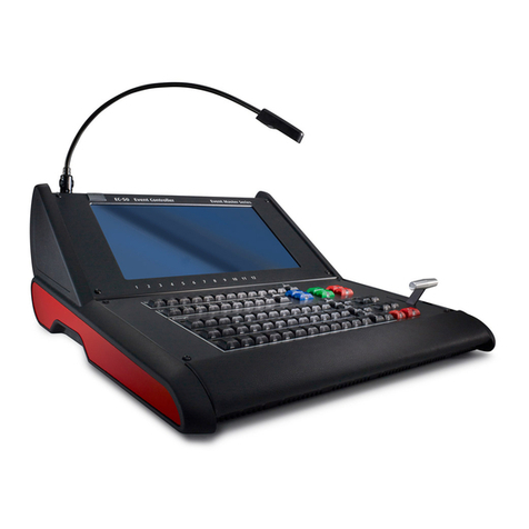
Barco Event Master EC-50 Series User manual

Barco

Barco Event Master EC-50 Series User manual

Barco EC-210 User manual

Barco

Barco EC-210 User manual

Barco Argus Owner's manual

Barco

Barco Argus Owner's manual

Barco Sedomat 2800 User manual

Barco

Barco Sedomat 2800 User manual

Barco EOS X Terminal User manual

Barco

Barco EOS X Terminal User manual

Barco Argus User manual

Barco

Barco Argus User manual

Barco Sedomat 2500 Owner's manual

Barco

Barco Sedomat 2500 Owner's manual

Barco Argus X Terminal User manual

Barco

Barco Argus X Terminal User manual

Barco Sedomat 5800 User manual

Barco

Barco Sedomat 5800 User manual

Barco TransForm A User manual

Barco

Barco TransForm A User manual

Barco Sedomat 5000 User manual

Barco

Barco Sedomat 5000 User manual

Barco EC-30 User manual

Barco

Barco EC-30 User manual

Popular Controllers manuals by other brands

Philips 9290 014 61062 installation guide

Philips

Philips 9290 014 61062 installation guide

OmniCure LX500 quick start guide

OmniCure

OmniCure LX500 quick start guide

Furious FPV Fortini F4 OSD REV.3 user manual

Furious FPV

Furious FPV Fortini F4 OSD REV.3 user manual

Norac UC4 Plus Rogator 64 Series installation manual

Norac

Norac UC4 Plus Rogator 64 Series installation manual

Mitsubishi Electric MELSEC-F FX-USB-AW user manual

Mitsubishi Electric

Mitsubishi Electric MELSEC-F FX-USB-AW user manual

SMC Networks MXQ6 Series Operation manual

SMC Networks

SMC Networks MXQ6 Series Operation manual

MTT MS3714 user manual

MTT

MTT MS3714 user manual

Omron V680-CA5D01-V2 instruction sheet

Omron

Omron V680-CA5D01-V2 instruction sheet

Savant LCB-DMX1 Deployment guide

Savant

Savant LCB-DMX1 Deployment guide

Orion OriLink 23408 manual

Orion

Orion OriLink 23408 manual

Asentria TeleBoss 830 user manual

Asentria

Asentria TeleBoss 830 user manual

Skov DOL 278AT user manual

Skov

Skov DOL 278AT user manual

Siemens Simatic S7-1500R manual

Siemens

Siemens Simatic S7-1500R manual

Timewave PK-232 MBX operating manual

Timewave

Timewave PK-232 MBX operating manual

LOVATO ELECTRIC ATL600 instruction manual

LOVATO ELECTRIC

LOVATO ELECTRIC ATL600 instruction manual

HTW HTW-KJR86A1E Installation and operation manual

HTW

HTW HTW-KJR86A1E Installation and operation manual

HIMA HIMatrix M45 manual

HIMA

HIMA HIMatrix M45 manual

Trek 610D Operator's manual

Trek

Trek 610D Operator's manual

manuals.online logo
manuals.online logoBrands
  • About & Mission
  • Contact us
  • Privacy Policy
  • Terms and Conditions

Copyright 2025 Manuals.Online. All Rights Reserved.