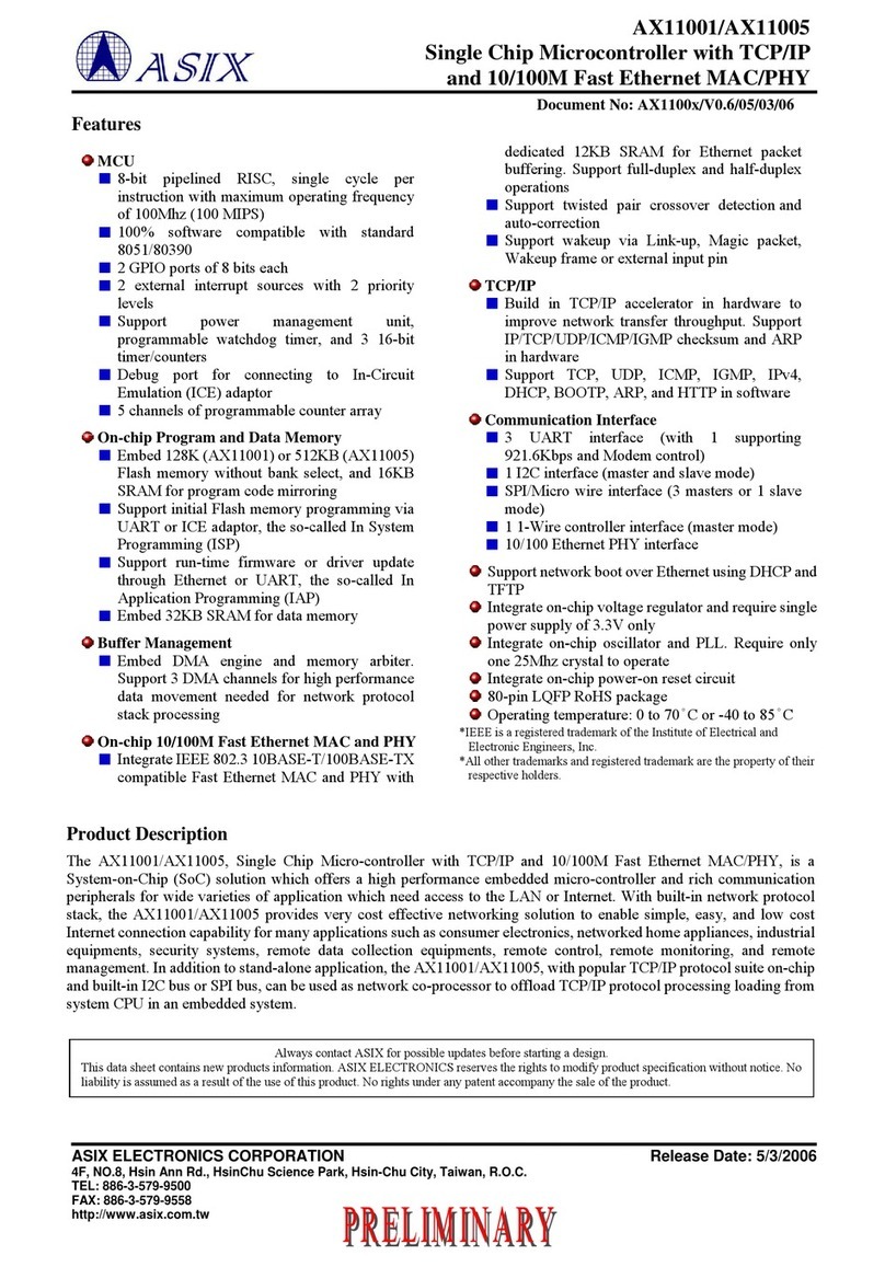
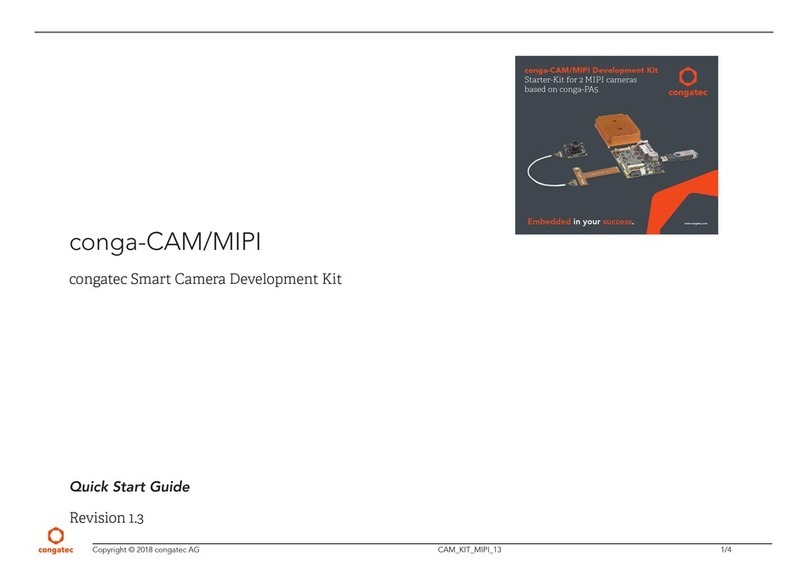
ASIX AX110 Series User manual

1
Copyright © 2006-2011 ASIX Electronics Corporation. All rights reserved.
AX110xx Development Kit
User Guide
Revision 1.70
Aug. 01st, 2011
AX110xx Development Kit
User Guide

2
Copyright © 2006-2011 ASIX Electronics Corporation. All rights reserved.
AX110xx Development Kit
User Guide
Revision History
Revision Date Description
1.0 2006/7/13 New release.
1.1 2006/7/21 1. Add Section 5 “I2C EEPROM Programming”, Appendix B. “80-pin
Development Board I2C EEPROM Default Setting” and Appendix
C. “128-pin Development Board I2C EEPROM Default Setting”.
2. Modify Figure 5 “AX11015 128-pin Development Board DIP
Switches” to correct the labels of P0_0~P0_7, P1_0~P1_7,
P2_0~P2_7 and Ethernet LEDs on AX11015 128-pin development
board.
3. Update Appendix D “80-pin Development Board schematic” to
AX1100x 80-pin Development Board schematics v1.01.
4. Update Appendix E “128-pin Development Board schematic” to
AX11015 128-pin Development Board schematics v1.02.
1.2 2007/4/2 1. Add Section 7-1 “COM Port Flash Programming Method Under
Windows”.
2. Add Section 8-3 “Upper Protocol Modules”.
3. Add Section 10 “AX110xx Mass Production Solutions”.
4. Add a note for RS-232 Null modem converter and AX11025 128-
pin Development Kit information in Section 1.
5. Add Section 4 “How to compile AX110xx development board demo
firmware”.
6. Update the pictures of the demo firmware web pages in Section 3.
7. Add the CAN interface configuration information in Section 5-2-7
and Appendix C for AX11025 128-pin development kit.
8. Modify Section 8-2 to add information about AX110xx uIP TCP/IP
module.
9. Update the Software Availability table in Appendix A.
10. Change the default value of 80-pin EEPROM offset 0x12 to 0x87 in
Appendix B.
11. Update 80-pin/128-pin development board reference schematics in
Appendix D and E.
1.3 2007/12/31 1. Add Section 3-4 to introduce AX11025 demo firmware functions.
2. Add Figure 5 “AX110xx Demo Firmware Run-time Code Starting
Address” in Section 4.
3. Add some more information in Section 2, 3-1-5, 3-2-1, 3-3-1, 6 and
7-3.
4. Add the “UARTH.EXE” utility information in Appendix A.
5. Update AX11025 Development Kit information in Section 1.
6. Update some information in Section 5-2.
7. Correct some typos in Section 3-1-4, 3-1-5.
8. Update the latest 128-pin development board reference schematic in
Appendix E.

3
Copyright © 2006-2011 ASIX Electronics Corporation. All rights reserved.
AX110xx Development Kit
User Guide
1.4 2008/8/25 1. Modified Section 2 to add Quick Start information.
2. Updated the revised Device Finder utility information in Section 3-
1.
3. Added Section 3-1-3 to indicate the EEPROM setup function
information of the Device Finder utility.
4. Modified the note messages in Section 5-2-9, 5-2-10, 5-2-11, 6-5.
5. Updated the revised Windows ISP tool information in Section 7-1.
6. Added Figure 17 “AX110xx Peripheral Software Modules” in
Section 8-1.
7. Modified some descriptions in Section 8-2.
8. Added Appendix D to indicate the AX11025 128-pin Development
Board I2C EEPROM Default Setting.
9. Updated Appendix E “80-pin Development Board schematic” to
AX11001&AX11005 80-pin Development Board schematic v1.10.
10. Updated Appendix F “128-pin Development Board schematic” to
AX11015&AX11025 128-pin De25lopment Board schematic v1.30.
1.5 2009/12/01 1. Remove Appendix E “AX11001&AX11005 80-pin Development
Board schematic”.
2. Remove Appendix F “AX11015&AX11025 128-pin Development
Board schematic”.
3. Correct some typos in Section 5-1-5, 5-2-13.
4. Added Section 8-1 AX110xx Ethernet Boot Loader.
5. Added Section 9-3, 9-4, 9-5 DoCD HAD2 Debugger description.
6. Modified some descriptions in Appendix A.
1.6 2010/04/13 1. Updated the revised “How to use DoCD HAD2 Debugger with Keil
IDE” in Section 9-5.
2. Updated Figure 8 and 18 “TFTPD32 TFTP/DHCP Server Setting”.
1.70 2011/08/01 1. Updated the information in Section 2-1 and 4.
2. Updated Figure 1, 2, 10, 11, 23.
3. Added ELNEC’s Device Programmer information in Section 10-2.
4. Updated the Section 9-4 description.
5. Changed the revision number to 3-digit format.

4
Copyright © 2006-2011 ASIX Electronics Corporation. All rights reserved.
AX110xx Development Kit
User Guide
Table of Contents
1.Introduction..........................................................................................8
2.Quick Start .........................................................................................12
2-1.How to compile AX110xx Demo Firmware Source Code?..........................14
2-2.How to program AX110xx Demo Firmware Code onto AX110xx Flash
memory?..................................................................................................................16
2-3.How to verify AX110xx Demo Firmware functionality? .............................17
2-4.How to start implementing my own AX110xx firmware?............................20
3.Software Function Description.........................................................21
3-1.Device Finder Utility .....................................................................................21
3-1-1.Main Window.......................................................................................................... 21
3-1-2.DF Setting Dialog................................................................................................... 22
3-1-3.EEPROM Dialog .................................................................................................... 23
3-1-4.Search Dialog ......................................................................................................... 24
3-1-5.IP Search Dialog..................................................................................................... 24
3-1-6.Device Setup Dialog ............................................................................................... 25
3-2.AX1100x 80-pin Development Board Web Server.......................................26
3-2-1.Web Server Main Page ........................................................................................... 26
3-2-2.LED Control Web Page.......................................................................................... 27
3-2-3.Temperature Sensor Web Page............................................................................... 28
3-3.AX11015 128-pin Development Board Web Server.....................................29
3-3-1.Web Server Main Page ........................................................................................... 29
3-3-2.LED Control Web Page.......................................................................................... 30
3-3-3.Temperature Sensor Web Page............................................................................... 32
3-4.AX11025 128-pin Development Board Web Server.....................................33
3-4-1.Web Server Main Page ........................................................................................... 33
3-4-2.LED Control Web Page.......................................................................................... 34
4.How to compile AX110xx development board demo firmware.....36
5.Development Board DIP Switches Setup.........................................39
5-1.AX1100x 80-pin Development Board DIP Switches Setting .......................39
5-1-2.S1 Switch Setting..................................................................................................... 40
5-1-3.S2 Switch Setting..................................................................................................... 40
5-1-4.S3 Switch Setting..................................................................................................... 40
5-1-5.S4 Switch Setting..................................................................................................... 41
5-1-6.S5 Switch Setting..................................................................................................... 41
5-1-7.S6 Switch Setting..................................................................................................... 42
5-1-8.S7 Switch Setting..................................................................................................... 42
5-1-9.S8 Switch Setting..................................................................................................... 42
5-2.AX11015/AX11025 128-pin Development Board DIP Switches Setting ....43
5-2-1.S1 Switch Setting..................................................................................................... 44
5-2-2.S2 Switch Setting..................................................................................................... 44

5
Copyright © 2006-2011 ASIX Electronics Corporation. All rights reserved.
AX110xx Development Kit
User Guide
5-2-3.S3 Switch Setting..................................................................................................... 44
5-2-4.S4 Switch Setting..................................................................................................... 44
5-2-5.S6 Switch Setting..................................................................................................... 45
5-2-6.S7 Switch Setting..................................................................................................... 45
5-2-7.S8 Switch Setting..................................................................................................... 45
5-2-8.S9 Switch Setting..................................................................................................... 47
5-2-9.S10 Switch Setting................................................................................................... 47
5-2-10.S11 Switch Setting................................................................................................... 48
5-2-11.S12 Switch Setting................................................................................................... 48
5-2-12.S14 Switch Setting................................................................................................... 49
5-2-13.S15 Switch Setting................................................................................................... 49
6.I2C EEPROM Programming............................................................50
7.Flash Programming...........................................................................54
7-1.COM Port Flash Programming Method Under Windows.............................54
7-1-1.Environment Setup.................................................................................................. 54
7-1-2.Starting Windows ISP Tool..................................................................................... 54
7-1-3.Example Procedure................................................................................................. 55
7-2.COM Port Flash Programming Method Under MS-DOS .............................56
7-3.Ethernet Boot Loader Flash Programming Method ......................................58
8.Software Sample codes......................................................................64
8-1.AX110xx Ethernet Boot Loader....................................................................64
8-1-1.AX110xx Ethernet Boot Loader Description .......................................................... 64
8-1-2.How to program AX110xx Ethernet Boot Loader code?........................................ 64
8-1-3.How to verify AX110xx Ethernet Boot Loader code?............................................. 64
8-2.Peripheral Software Modules ........................................................................65
8-3.TCP/IP Stacks ................................................................................................65
8-4.Upper Protocol Modules................................................................................67
8-5.More sample codes ........................................................................................67
9.Software Development Tools.............................................................68
9-1.Software Compiler Tool ................................................................................68
9-2.Software Debugger Tool................................................................................68
9-3.DoCD HAD2 Debugger Key Features ..........................................................69
9-4.How to setup DoCD HAD2 Debugger Environment? ..................................71
9-5.How to use DoCD HAD2 Debugger with Keil IDE?....................................80
10.AX110xx Mass Production Solutions...............................................85
10-1.Advantech Equipment Corporation’s Flash Programmer Solution...............85
10-2.ELNEC’s Flash Programmer Solution ..........................................................86
10-3.AX110xx Manufacture Program Solution.....................................................87
Appendix A. Software Availability..........................................................88

6
Copyright © 2006-2011 ASIX Electronics Corporation. All rights reserved.
AX110xx Development Kit
User Guide
Appendix B. AX1100x 80-pin Development Board EEPROM Default
Setting........................................................................................................90
Appendix C. AX11015 128-pin Development Board EEPROM Default
Setting........................................................................................................91
Appendix D. AX11025 128-pin Development Board EEPROM Default
Setting........................................................................................................92

7
Copyright © 2006-2011 ASIX Electronics Corporation. All rights reserved.
AX110xx Development Kit
User Guide
List of Figures
Figure 1.AX1100x 80-pin Development Board ............................................................................................. 9
Figure 2.AX11015 128-pin Development Board ......................................................................................... 10
Figure 3.AX11025 128-pin Development Board ......................................................................................... 11
Figure 4.AX110xx Demo Firmware Run-time Code Starting Address .......................................................13
Figure 5.AX110xx Demo Firmware Code Flash Programming Methods.................................................... 16
Figure 6.AX110xx Development Board Demo System ............................................................................... 17
Figure 7.Windows machine COM Port Setting Example............................................................................. 18
Figure 8.The TFTPD32 TFTP/DHCP Server Setting ..................................................................................18
Figure 9.AX110xx Demo Firmware Run-time Code Starting Address .......................................................36
Figure 10. The DIP Switches of AX1100x 80-pin Development Board......................................................... 39
Figure 11. The DIP Switches of AX11015/AX11025 128-pin Development Boards..................................... 43
Figure 12. The Main Window of Windows ISP Tool ..................................................................................... 54
Figure 13. AX1100x 80-pin Development Board UART 0 Interface ............................................................. 56
Figure 14. AX11015/AX11025 128-pin Development Board UART 0 Interface........................................... 56
Figure 15. Flash Programming Utility Command Lines ................................................................................. 57
Figure 16. Flash Programming Time............................................................................................................... 57
Figure 17. The COM Port Setting for AX110xx UART0 Debug Console...................................................... 58
Figure 18. The TFTPD32 TFTP/DHCP Server Setting................................................................................... 59
Figure 19. The TFTPD32 TFTP/DHCP Server Log Messages....................................................................... 60
Figure 20. AX110xx Peripheral Software Modules ........................................................................................ 65
Figure 21. Features Supported in lwIP, Original uIP and AX110xx uIP TCP/IP Modules ............................ 66
Figure 22. The Architecture of AX110xx Upper Protocol Modules ............................................................... 67
Figure 23. DoCD HAD2 Hardware Debugger Module................................................................................... 68
Figure 24. AEC’s LABTOOL-848XP Turbo Gang Programmer ................................................................... 85
Figure 25. ELNEC’s BeeHive 208S and 204 Programmer ............................................................................. 86
Figure 26. AX110xx Manufacture Program.................................................................................................... 87
Figure 27. AX110xx Software Availability .................................................................................................... 89
Figure 28. AX1100x 80-pin Development Board EEPROM Default Setting................................................. 90
Figure 29. AX11015 128-pin Development Board EEPROM Default Setting............................................... 91
Figure 30. AX11025 128-pin Development Board EEPROM Default Setting............................................... 92

8
Copyright © 2006-2011 ASIX Electronics Corporation. All rights reserved.
AX110xx Development Kit
User Guide
1. Introduction
This document provides the overviews of AX110xx Development Kit.
ASIX Electronics provides three kinds of AX110xx Development Kits for customers’ reference.
AX1100x 80-pin Development Kit is for users to evaluate AX11001/AX11005 products,
AX11015 128-pin Development Kit is for users to evaluate AX11015 product and AX11025
128-pin Development Kit is for users to evaluate AX11025 product. If you need to purchase the
AX110xx development boards or reference design boards, please contact ASIX's Sales
([email protected]) for details.
AX1100x 80-pin development kit consists of five components:
AX1100x 80-pin development board with a 1-Wire temperature sensor,
AX110xx Development Kit CD,
One RS-232 cable with a Null modem converter,
One RJ-45 Ethernet cable,
One 5V/3A AC/DC power adapter
AX11015 128-pin development kit consists of five components:
AX11015 128-pin development board with a 1-Wire temperature sensor,
AX110xx Development Kit CD,
One RS-232 cable with a Null modem converter,
One RJ-45 Ethernet cable,
One 5V/3A AC/DC power adapter
AX11025 128-pin development kit consists of five components:
AX11025 128-pin development board,
AX110xx Development Kit CD,
One RS-232 cable with a Null modem converter,
One RJ-45 Ethernet cable,
One 5V/3A AC/DC power adapter

9
Copyright © 2006-2011 ASIX Electronics Corporation. All rights reserved.
AX110xx Development Kit
User Guide
Figure 1. AX1100x 80-pin Development Board
Note: The DoCD HAD2 module is not included in the AX110xx Development Kit.

10
Copyright © 2006-2011 ASIX Electronics Corporation. All rights reserved.
AX110xx Development Kit
User Guide
Figure 2. AX11015 128-pin Development Board
Note: The DoCD HAD2 module is not included in the AX110xx Development Kit.

11
Copyright © 2006-2011 ASIX Electronics Corporation. All rights reserved.
AX110xx Development Kit
User Guide
Figure 3. AX11025 128-pin Development Board

12
Copyright © 2006-2011 ASIX Electronics Corporation. All rights reserved.
AX110xx Development Kit
User Guide
2. Quick Start
This section describes the information about how to start evaluating the AX110xx development
board and implementing the firmware code on the AX110xx target applications.
The AX110xx Development Kit CD provides all the necessary AX110xx technical documents,
reference schematics, demo firmware source codes and utilities. Users just need to prepare the
Keil IDE development tool (refer to Section 9-1: Software Compiler Tool for details) before
implementing AX110xx firmware on your target applications. The DCD's DoCD HAD2
debugger is optional for AX110xx (refer to Section 9-2: Software Debugger Tool for details)
because all AX110xx demo firmware source codes already support the UART console
debugging function.
Please prepare the following equipments before starting to evaluate the AX110xx development
board:
zWindows machine
zKeil IDE development tool (http://www.keil.com/c51/selector.asp)
zAX110xx development board with 1 5V/3A AC/DC power adapter
zAX110xx Development Kit CD
¾AX110xx development board demo firmware source code
¾AX110xx boot loader binary code
¾AX110xx I2C EEPROM utility binary code
¾AX110xx Windows ISP
¾AX110xx Device Finder utility
¾TFTPD32 TFTP/DHCP Server utility
zRS-232 NULL modem cable (*Note)
zRJ-45 Ethernet cable
Note: The following RS-232 Null modem converter should be connected to the RS-232 cable
included in AX110xx development board package; otherwise, the AX110xx couldn’t establish
the connection with PC or other RS-232 devices.

13
Copyright © 2006-2011 ASIX Electronics Corporation. All rights reserved.
AX110xx Development Kit
User Guide
AX110xx demo firmware source code supports two project files (BUILD\AX110xx.Uv2 and
BUILD_RT\AX110xx.Uv2) for different AX110xx applications. The BUILD\AX110xx.Uv2
project file is suitable to the AX110xx applications that need not use the AX110xx Ethernet boot
loader code and the starting address of AX110xx firmware is allocated at 0. The
BUILD_RT\AX110xx.Uv2 project file is suitable to the AX110xx applications that work with
AX110xx Ethernet boot loader code and the starting address of AX110xx firmware is allocated
at 24K. The AX110xx Flash range between offset 16K and 24K can be used to store some
software variables of AX110xx firmware such as the configuration settings of Device Finder
utility. Please refer to the following figure for more details.
Figure 4. AX110xx Demo Firmware Run-time Code Starting Address
AX110xx
Demo Firmware
Run-time Code
AX110xx
Demo Firmware
Run-time Code
Range for Saving SW
Variables
Boot Loader
U
p
to 2M
Starting address
from 24
K
0
16
K
AX110xx Demo Firmware
with Boot Loader
Up to 2M
Starting address
from 0
AX110xx Demo Firmware
without Boot Loader

14
Copyright © 2006-2011 ASIX Electronics Corporation. All rights reserved.
AX110xx Development Kit
User Guide
2-1. How to compile AX110xx Demo Firmware Source Code?
The following are the procedures to compile the AX110xx demo firmware source code. Please
refer to Section 4: How to compile AX110xx development board demo firmware for more
details.
a) Please copy a proper AX110xx demo firmware source code (e.g. the whole “AX1100x 80-
pin Development Board” folder) from the “Demo Firmware” subdirectory of AX110xx
Development Kit CD to the Windows machine (e.g. “D:\AX1100x 80-pin Development
Board”).
b) Change to the AX110xx demo firmware source folder (e.g. “D:\AX1100x 80-pin
Development Board”) on the Windows machine.
c) Open a proper project file (BUILD\AX110xx.Uv2 or BUILD_RT\AX110xx.Uv2) from the
AX110xx demo firmware source code in the Keil IDE development tool.
d) Select Rebuild target on the Keil IDE to compile the AX110xx demo firmware source code.

15
Copyright © 2006-2011 ASIX Electronics Corporation. All rights reserved.
AX110xx Development Kit
User Guide
e) After the source code was compiled successfully, you should see the following similar
messages on the Keil IDE development tool. The following is the sample compiler messages
for the BUILD_RT\AX110xx.Uv2 project file of AX1100x 80-pin demo firmware source
code.
Note: The AX110xx.Uv2 project file is for Keil IDE uVision 2 & 3 while the AX110xx.uvproj
project file is for Keil IDE uVision 4 only.
f) You can program the re-compiled AX110xx firmware code onto the AX110xx Flash through
a proper AX110xx Flash Programming method. Please refer to Section 2-2: How to
program AX110xx Demo Firmware Code onto AX110xx Flash memory for more details.

16
Copyright © 2006-2011 ASIX Electronics Corporation. All rights reserved.
AX110xx Development Kit
User Guide
2-2. How to program AX110xx Demo Firmware Code onto AX110xx Flash
memory?
There are two solutions to program the AX110xx firmware run-time code onto the AX110xx
Flash memory of your target applications. One solution is to program the AX110xx firmware
run-time code with starting address 0 onto AX110xx Flash memory by running the AX110xx
Windows ISP tool directly; another one is to program the AX110xx firmware run-time code with
starting address 24K onto AX110xx Flash memory through the AX110xx Ethernet boot loader.
In this case, you should program the AX110xx Ethernet boot loader code onto AX110xx Flash
memory by running the AX110xx Windows ISP tool first.
The AX110xx firmware run-time code with starting address 0 compiled by using the
BUILD\AX110xx.Uv2 project file should be programmed onto the AX110xx Flash memory by
using the Windows ISP UART0 Flash programming method. Please refer to Section 7-1: COM
Port Flash Programming Method Under Windows for more details.
The AX110xx firmware code with starting address 24K compiled by using the
BUILD_RT\AX110xx.Uv2 project file should be programmed onto the AX110xx Flash memory
by using the AX110xx Ethernet Boot Loader Flash programming method. Please refer to Section
7-3: Ethernet Boot Loader Flash Programming Method for more details.
Figure 5. AX110xx Demo Firmware Code Flash Programming Methods
AX110xx
Demo Firmware
Run-time Code
AX110xx
Demo Firmware
Run-time Code
Range for Saving SW
Variables
Boot Loader
U
p
to 2M
Starting address
from 24
K
0
16
K
U
p
to 2M
Starting address
from 0
AX110xx Demo Firmware
with Boot Loader
1. Run WinISP to program
AX110xx boot loader
via the UART0
2. Program AX110xx run-time
code via the boot loader
AX110xx Demo Firmware
without Boot Loader
1. Run WinISP to program
AX110xx run-time code
via the UART0 directly

17
Copyright © 2006-2011 ASIX Electronics Corporation. All rights reserved.
AX110xx Development Kit
User Guide
2-3. How to verify AX110xx Demo Firmware functionality?
The demo system illustration of AX110xx development board is shown in below figure.
Figure 6. AX110xx Development Board Demo System
AX110xx development board demo firmware provides a basic Web Server to support the LED
Control and Temperature Sensor functions and will request an IP address from DHCP server. If
there is no DHCP server on the network, AX110xx development board firmware will assign a
default IP address (e.g. 192.168.0.3).
The following are the detailed procedures about how to verify AX110xx demo firmware
functionality,
1. Connect the Ethernet port of AX110xx development board and the Ethernet port of Windows
PC with a RJ-45 cable.
2. Connect the UART0 interface of AX110xx development board and the COMx port of
Windows machine with a RS-232 Null modem cable.
Note: This step is optional and can be skipped if the user need not check the UART0
debugging messages of AX110xx demo firmware.
3. Connect the 5V/3A AC/DC power adapter to AX110xx development board.
4. Boot up the Windows machine with Ethernet interface that is configured to a proper IP
address (e.g. 192.168.0.190).

18
Copyright © 2006-2011 ASIX Electronics Corporation. All rights reserved.
AX110xx Development Kit
User Guide
5. Run Hyper Terminal application to create a connection between AX110xx board and the
Windows machine, the COMx port should be set to 9600 baud rate, 8 data bit, NO parity
check, 1 stop bit and NO flow control.
Note: Windows 7/Vista doesn’t support the Hyper Terminal Tool; please find the third party
utility (e.g. Tera Term) to see the UART debug messages on these Operation Systems.
Figure 7. Windows machine COM Port Setting Example
6. Startup the TFTPD32 DHCP/TFTP Server utility (i.e. TFTPD32.EXE) on the Windows
machine and follow the following procedures to configure the TFTPD32 DHCP Server.
Please refer to below figure for more details.
Figure 8. The TFTPD32 TFTP/DHCP Server Setting

19
Copyright © 2006-2011 ASIX Electronics Corporation. All rights reserved.
AX110xx Development Kit
User Guide
a) Set the “IP pool starting address“ field (e.g. 192.168.0.3) to the same subnet mask with
the “Server interfaces IP address” (e.g. 192.168.0.190).
b) Set the “Size of pool” field to a number larger than 0 (e.g. 10).
c) Press the [Save] button to take effect the new setting.
7. Power ON the AX110xx development board, and then you should see the following debug
messages of AX110xx Ethernet boot loader and demo firmware run-time code on the
HyperTerminal console.
AX110xx bootloader v3.1.0 version for DoCD HAD Debugger
1. Execute Runtime.
2. Download runtime via RS232.
3. Download runtime via Ethernet.
4. Download new bootloader via Ethernet.
Please input 1,2,3 or 4 to execute above :
Get new IP : c0a8000a
Get subnet mask : ffffff00
Get gateway : c0a80001
TFTP server IP : c0a80032
Download file total length = 0x2c0cf bytes.
download ok.
Wait runtime code.
UART-0 init ok.
UART-2 init ok.
ASIX AX110xx 128PIN Demo Firmware V3.0.0 (06/07/11 16:39:53)
DHCP init ok.
GCONFIG_Init()..
…
DHCP request... IP: 192.168.0.3
…
12.EEPROM DATA: 21 3c 0f 80 30 00 54 0c 00 c6 0e 00 f2 05 10 e0
1d 19 87 00 ff ff ff ff 10 03 00 a8 c0 00 ff ff
ff 04
GUDPBC_Init()...
8. Now, you can run the AX110xx Device Finder utility to search the AX110xx development
board and enter the AX110xx web server by pressing the “Web Browser” button on the
Device Finder main window. Please refer to Section 3-1: Device Finder Utility for more
details.

20
Copyright © 2006-2011 ASIX Electronics Corporation. All rights reserved.
AX110xx Development Kit
User Guide
2-4. How to start implementing my own AX110xx firmware?
The AX110xx Development Kit CD provides the workable AX110xx demo firmware source
codes. Customers can easily implement their own AX110xx firmware based on the AX110xx
demo firmware source code.
Before start modifying the AX110xx demo firmware source code to reach the requirements of
your AX110xx target applications, we strongly suggest you to study the AX110xx Software
User Guide and AX110xx Upper Protocol Developer Guide first. These documents describe
the detailed information of all AX110xx driver and upper protocol modules.
Please refer to Section 8: Software Sample codes for the details of all available AX110xx
drivers and upper protocols. You can get all AX110xx driver modules source codes from the
AX110xx Development Kit CD. If you need the available AX110xx upper protocol source codes,
This manual suits for next models
3
Table of contents
Other ASIX Microcontroller manuals
Popular Microcontroller manuals by other brands

Lattice
Lattice LPTM10-12107-DEV-EVN quick start
Texas Instruments
Texas Instruments Serial Programming Adapter MSP430 Student guide
Microsemi
Microsemi M1AFS-EMBEDDED-KIT-2 quick start guide
Cypress
Cypress FM4 Series Peripheral Manual

mikroElektronika
mikroElektronika BIGdsPIC6 user manual
Renesas
Renesas DK-S124 user manual

