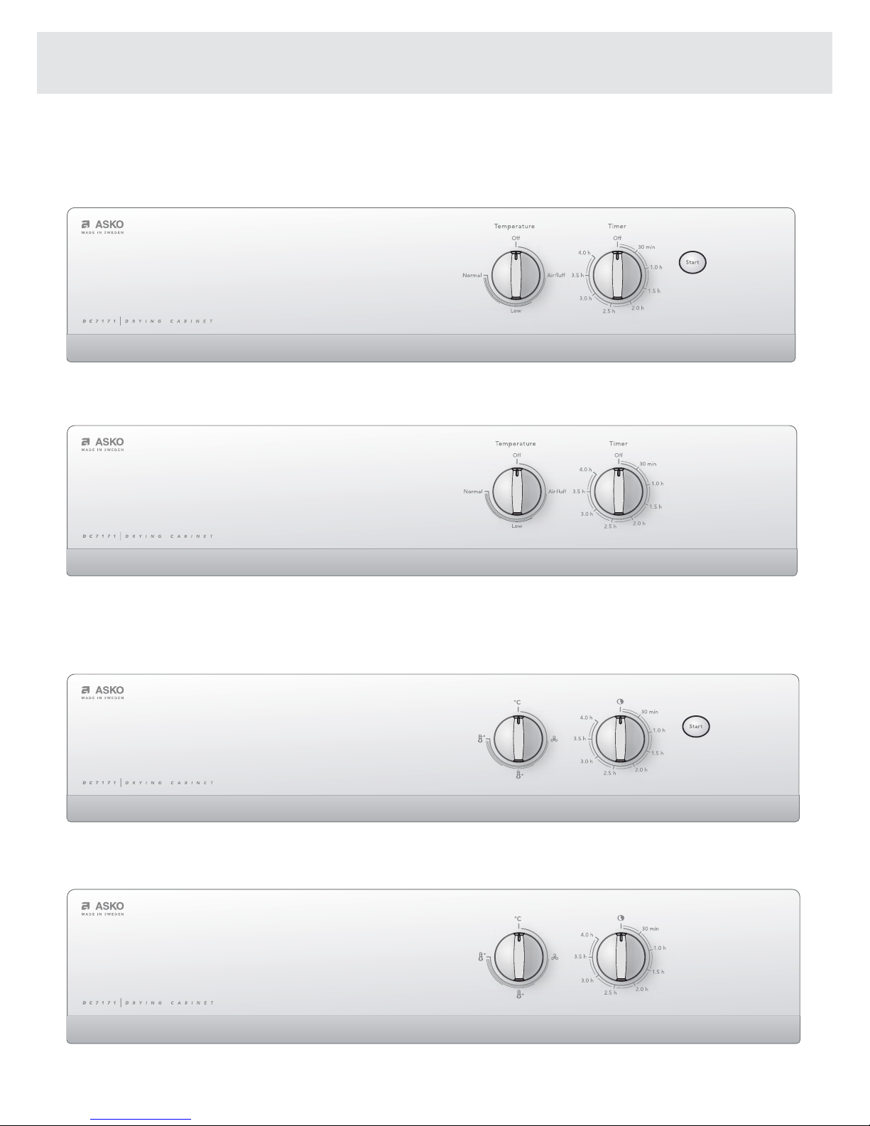
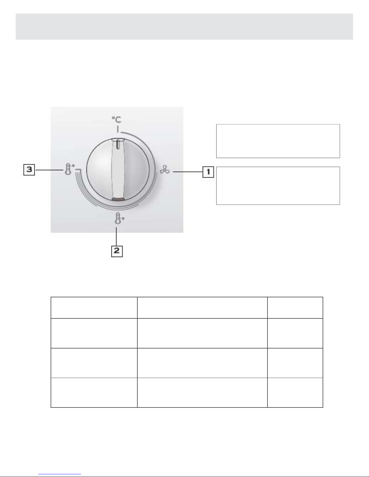
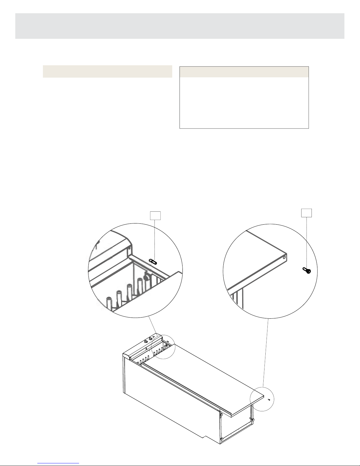
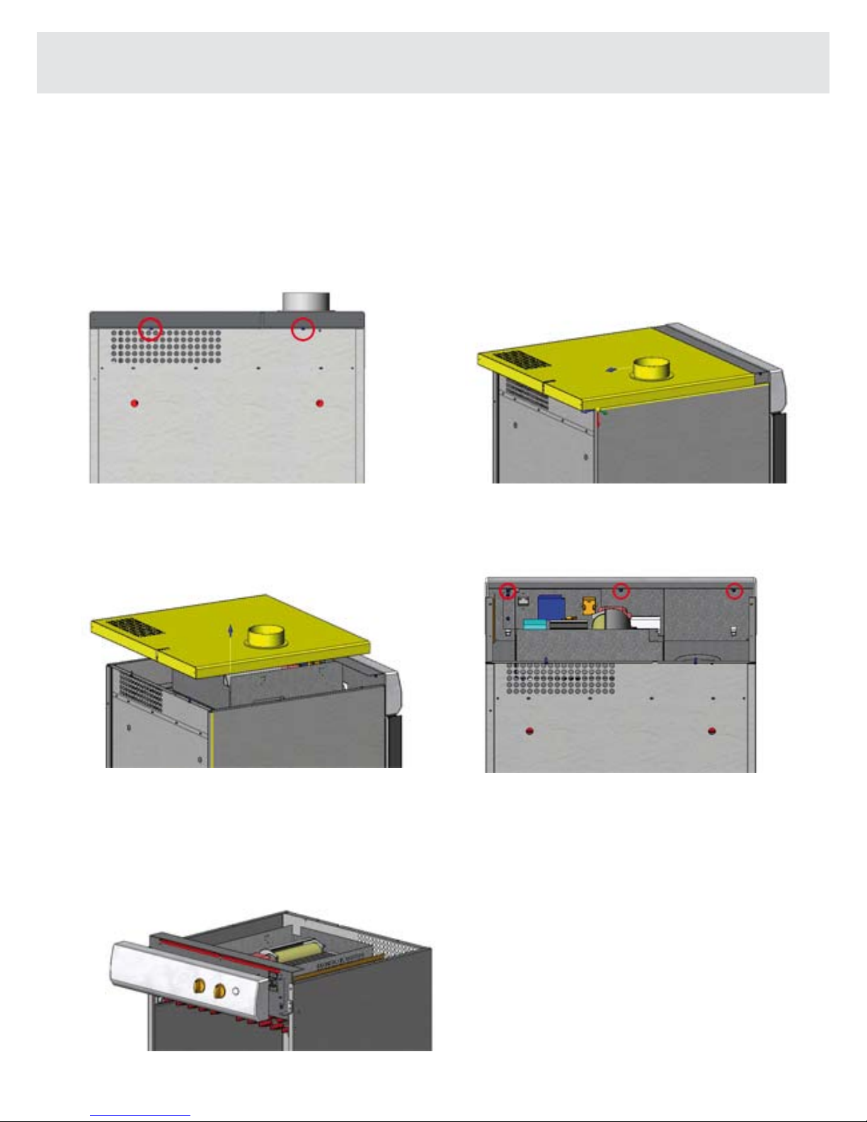
Asko DC 7171 User manual

SERVICE MANUAL
DRYING CABINET

Contents
Servicing………………………………………………………...
3
Presentation of the different models…………………………….
4
Setting the temperature selector knob…………………………...
5
Control panel…………………………………………………….
6
Placing the door the other way round…………………………...
7
Changing the casing unit………………………………………...
8
Changing the panel………………………………………………
9
Changing the selector knob……………………………………...
10
Changing the fan/motor and the protection against overheating..
11
Changing the element……………………………………………
12
Changing the thermostat………………………………………...
13
Changing the timer………………………………………………
14
Changing the start button (exterior)……………………………..
15
Changing the start button (interior)……………………………..
16
Changing the contactor………………………………………….
17
Changing the door contact breaker……………………………...
18
Changing the hangers……………………………………………
19
Technical information 120V…………………………………….
20
Circuit diagram DC7171 with start button, 120V……………….
21
Trouble shooting...........................................................................
22

Servicing
Before you contact customer service,
you should find out the designation of the model, its
type and its serial number. The designation of the
model is inscribed on the cabinet control panel. The
type and the serial number are inscribed on the iden-
tification plate which is placed on the inside of the
cabinet.
DC XXXX
?????????????????????
????????????????
????????????????
1
2
3
4
5
Typskylt
1. Model
2.
3. Article number
4. Serial number (12 figures)
5. Type
3
Identification plate (inside)

Presentation of the different models
ASKO DC7171 with start button, with text
ASKO DC7171 without start button, with text
ASKO DC7171 without start button, with symbols
ASKO DC7171 with start buttons, with symbols
4

Setting the temperature selector knob
5
Setting Articles to be dried Temperature
1
Air fluff
Foam-rubber products, plastics,
heat-sensitive items
Fan only
2
Low
Sports clothing, underwear, shirts,
blouses, silk goods, machine-
washable knit products
Low
3
Normal
Heavy work clothing, denim, cotton
garments, cotton sweatshirts
Normal
Do not use heat when drying
foam-rubber lined clothing or
similar articles
The cycle control regulates the
temperature on a stepless scale,
from no heat to the normal position
with full temperature.

Control panel
1. Temperature setting
2. Timer
3. START-button (only certain markets)
6

Placing the door the other way round
7
1
2
Excessive Weight Hazard
Use two or more people to handle the
drying cabinet.
Failure to do so can result in back or
other injury.
Warning!
You can change your door swing from a
right-side opening to a left-side opening, if
desired.
1. Place the drying cabinet on its back.
2. Remove the hinge pin at the lower hinge
(1) and lift off the door.
3. Remove the plastic plug and press it in
place on the lower hinge on the opposite
site.
4. Remove the hinge pin from the upper hinge
(2) and fit it to the opposite side.
5. Unscrew the glove hanger on the inside
of the door and turn it completely around.
The glove hanger is secured with four
screws.
6. Rotate the door, position it and secure it
with the lower hinge pin (1).
Reverse door swing

Changing the casing unit
Disengage the cabinet from the wall and pull it forward!
1- Loosen two screws at the rear edge of the
cabinet
2- Draw the cover backwards
3- Lift off the cover 4- Unscrew four screws on the inside of the
top cover plate
5- Unscrew two screws on the side of the casing unit, draw it backwards and lift it off.
8

Changing the panel
Disengage the cabinet from the wall and pull it forward!
1- Loosen two screws at the rear edge
of the cabinet
2- Draw the cover backwards
3- Lift off the cover 4- Unscrew three screws behind the panel
5- Stand in front of the cabinet, slanting the upper part of the panel outwards and care-
fully draw it upwards (to release the catches) and then outwards.
9

Changing the selector knob
Disengage the cabinet from the wall and pull it forward!
1- Loosen two screws at the rear edge
of the cabinet
2- Draw the cover backwards
3- Lift off the cover 4- Unscrew three screws behind the panel
5- Stand in front of the cabinet, slanting the upper
part of the panel outwards and carefully draw it
upwards (to release the catches) and then outwards.
PRESS IN
6. On the back side of the panel the selector
knobs are held firmly in place with two catches.
Press in the catches to release the selector
knob and draw it out.
When installing, press in the selector knob so that the catches snap into place.
(This is done when the panel is mounted on the cabinet) 10

Changing the fan/motor and the protection
against overheating
Disengage the cabinet from the wall and pull it forward!
1- Loosen two screws at the rear edge
of the cabinet
2- Draw the cover backwards
3- Lift off the cover 4- It is firmly fixed with 4 screws
Changing the protection against overheating
Fixed on the element, screwed firmly into place with 2 screws
11

Changing the element
Disengage the cabinet from the wall and pull it forward!
1- Loosen two screws at the rear edge
of the cabinet
2-Draw the cover backwards
3- Lift off the cover 4- Unscrew four screws on the inside of the
top cover plate
5- Unscrew two screws on the side of the casing unit, draw the casing unit back-
wards and lift it off.
6. On the underside of the casing unit you will find 4
screws which hold the element firmly in place.
12

Changing the thermostat
Disengage the cabinet from the wall and pull it forward!
1- Loosen two screws at the rear edge
of the cabinet
2- Draw the cover backwards
3- Lift off the cover 4- Unscrew four screws on the inside of the
top cover plate
5- Unscrew two screws on the side of the
casing unit, draw the casing unit backwards
and lift it off. 6. Remove the 2 screws from the front,
take the bulb out of the bulb socket
Screws for the thermostat 13

Changing the timer
Disengage the cabinet from the wall and pull it forward!
1- Loosen two screws at the rear of
the cabinet
2- Draw the cover backwards
3- Lift off the cover 4- Unscrew four screws on the inside of the
top cover plate
5- Unscrew two screws on the side of the
casing unit, draw the casing unit backwards
and lift it off. 6. TRemove the 2 screws which hold the timer
in place on the front side of the casing unit.
Screws
14

Changing the start button (exterior)
Disengage the cabinet from the wall and pull it forward!
1- Loosen two screws at the rear edge
of the cabinet
2- Draw the cover backwards
3- Lift off the cover 4- Unscrew three screws behind the panel
5- Stand in front of the cabinet, slanting the upper
part of the panel outwards and carefully draw it
upwards (to release the catches) and then
outwards.
PRESS IN
6. On the back side of the panel the selector
knobs are held firmly in place with two catches.
Press in the catches to release the start button
and draw it out.
When installing, press in the start button so that the catches snap into place.
(This is done when the panel is mounted on the cabinet) 15

Changing the start button (interior)
Disengage the cabinet from the wall and pull it forward!
1- Loosen two screws at the rear edge
of the cabinet
2- Draw the cover backwards
3- Lift off the cover 4- Unscrew four screws on the inside of the
top cover plate
5- Unscrew two screws on the side of the casing unit, draw the casing unit back-
wards and lift it off.
PRESS IN the catches on both sides
and draw out the start button. 16

Changing the contactor
Disengage the cabinet from the wall and pull it forward!
1-Loosen two screws at the rear edge
of the cabinet
2- Draw the cover backwards
3- Lift off the cover 4- Change the contactor by pressing it
downwards and backwards at the same time
that you lift off the back part of the contactor.
17

Changing the doorswitch
Disengage the cabinet from the wall and pull it forward!
1- Loosen two screws at the rear edge
of the cabinet
2- - Draw the cover backwards
3- Lift off the cover 4- Unscrew three screws behind the panel
5- Stand in front of the cabinet, slanting the upper
part of the panel outwards and carefully draw it
upwards (to release the catches) and then
outwards.
6. Unclip the securing catch and draw out
the doorswitch
Unclip
18

Changing the hangers
Detach the hanger stop on both sides and pull out the hangers.
Changing the door edging strip
HANGER STOP
Turn up the edging strip, unscrew the screws from the metal panel and change the edging strip.
19

Technical data
20
Capacity: About 7 1/2 lbs (3.5 kg) of laundry (cotton)
Dewatering capacity: 0.56 ounce/min (16 gram/min)
Electrical connection: Single-phase, 120 V, 60 Hz
Motor: 43 W
Heating element output: 1200 W
Overheating protection: Yes
Time switch: Adjustable up to 4 hours
Hanging length: 630 in. (16 meters)
Dimensions: Height 68” (173.0 cm) Adjustable 67 3/4” - 68 3/4”
(172.0 cm - 174.5 cm)
Width 23 7/16” (59.5 cm)
Depth 24” (61.0 cm)
Weight: About 133 lbs (60 kg)
Color: White or Titanium
Noise level: Max. 58 dB(A)
Energy consumption and drying times
Drying spun-dried wash *)
Setting Energy consumption Drying time Heat
Low 0.33 kWh/lb (0.72 kWh/kg) laundry About 210 min. 45°C (113°F)
Normal 0.34 kWh/lb (0.75 kWh/kg )laundry About 130 min. 65°C (149°F)
Manufacturing standards
See the cabinet’s rating plate
*) The values can vary depending on spin dry speeds.
Installation spacing for custom cabinetry
For built-in installation, minimum ventilation openings in the top and between the cabinet and
the rear wall must be ½” (13 mm).
Exhaust
When the drying cabinet is working, 45 m³ of moist air are evacuated per hour. This air is
taken from the room where the unit is installed.
Technical characteristics
Other manuals for DC 7171
5
Table of contents
Other Asko Dryer manuals