Asko TL751 XXLW User manual

Service Guide
Tumble dryer
Version1
2008.02.13
Asko TL751 XXLW
TL751 XXLT

Contents
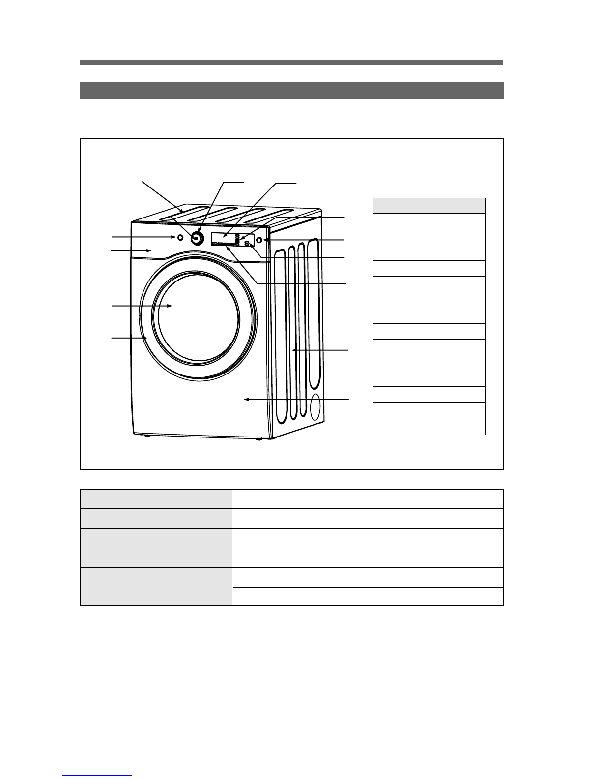
❏ Tumble Dryer Basics...............................................................................................2
❏ Dryer Specification..................................................................................................4
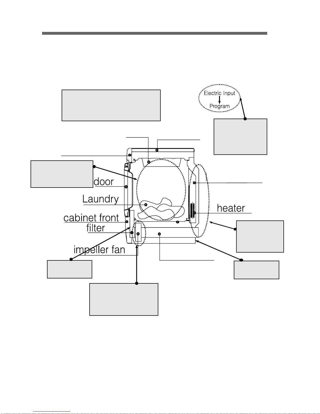
❏ Operating Mechanism Diagram (Electric Type)....................................................5
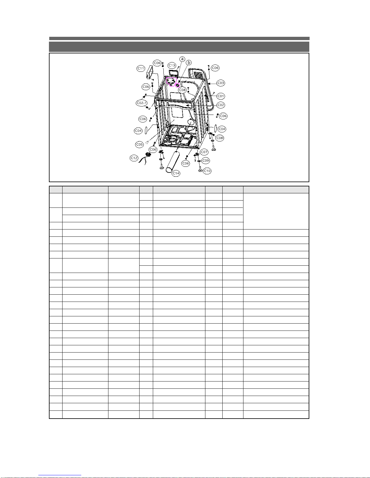
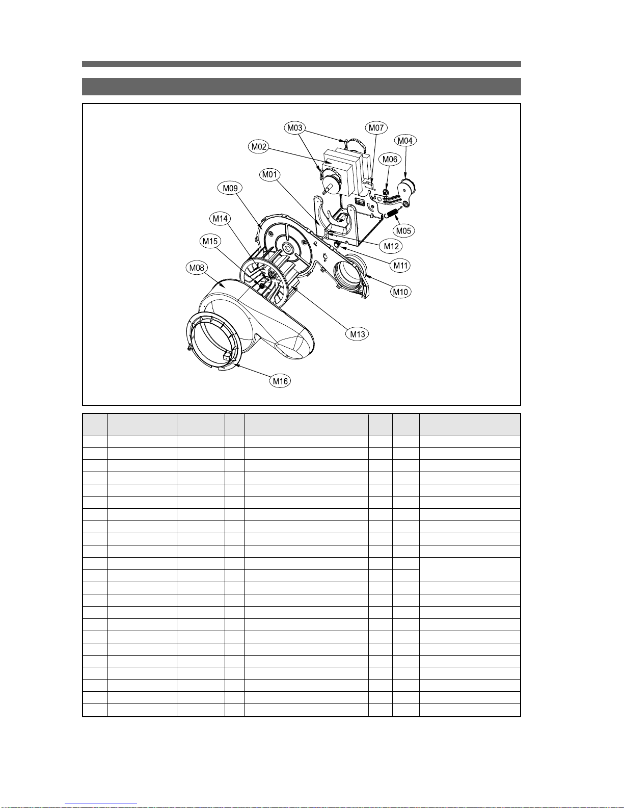
❏ Parts List by Ass’y...................................................................................................6
❏ PCB Function Specification .................................................................................16
❏ Drum Dryer Troubleshooter.................................................................................29
❏ Dryer Installation...................................................................................................31
❏ Dryer Service Notices ..........................................................................................35
❏ Dryer electronic devices
Electric Parts List - Electric Clothes Dryer...........................................................36
Fan Thermostat ....................................................................................................37
Thermostat Cut-Out .............................................................................................38
Thermostat Control...............................................................................................39
Lamp Assembly ...................................................................................................40
Door Switch ..........................................................................................................41
Heater Assembly..................................................................................................42
Belt Switch (Microswitch)....................................................................................43
Fan Thermistor ....................................................................................................45
Dryer Motor ..........................................................................................................46

2
Paddles in a rotating drum move the laundry front to back ashot air heated by electricity (or gas) dries the
laundry using timeddry or sensor controlled dry programs.
❑ Tumble Dryer
1. Tumble Dryer Basics
◆Large Capacity/Time-Saving
• A large quantity of laundry can be dried at a time, saving energy as well as time.
◆Automatic Digital Dry
• The digital sensor measures the humidity of laundry for optimum drying.
◆Large Door
• The dryer has a large transparent door for convenient monitoring of laundry.
◆Lint Filter
• Lint and dust are filtered during the drying process.
◆Sterilizing Dry
• The high-temperature air dries laundry with sterilizing effects.
◆Drying Shoes
• The drying rack provided with the unit is helpful when drying shoes as well as sensitive fabric.
◆Child Safety
• The drum stops automoatically as soon as the door is opened. The unit will not restart until
the Start button has been pressed.
2. Key Features

◆Dry Time
• Adjust the length of time for drying.
◆Sensor Dry
• Automatically dry according to the types of laundry.
◆Rack Dry
• Dry sensitive fabric (e.g. sweaters, silk, lingerie) on the rack.
◆Anti-crease
• Prevent wrinkles in case laundry is left in the drum after the drying process.
◆Damp Signal
• Buzzer sounds when the laundry is just damp enough to be ironed.
◆ Delay Start
• Delays starting the unit for between 1-12 hours in 1 hour increments.
3
3. Key Functions

4
❑ Dryer Specification
1. Product Overview
Dimensions 27"(W)x 32.4"(D)x 40.2"(H)
Weight 128 lbs(58.5 kg)
Capacity IEC 7.3 cu.ft (22.9lb)
Rated Power Power source : Electric
Rating 120/240V 60Hz
23.5A 5300w
No. Parts
1DOOR FRAME
2DOOR GLASS
3 CONTROL PANEL
4 CABINET FRONT
5TOP
6 CABINET
7CYCLE OPTIONS
8 PROGRAM OPTIONS
9PROGRAMS
10 ROGRAM KNOB
11 DELAY START BUTTON
12 START/STOP BUTTON
13 POWER BUTTON
14 DISPLAY WINDOW
914
8
1
2
1
1
7
6
4
1
2
3
13
10
5

5
?Operating Mechanism
• Controller operation
• Operator/heater/air supplier/ventilator operation
• Automatic operation of the controller
• Drying by the automatic sensor
1. Controller
• MAIN PCB
• FRONT PCB
• HARNESS
• TERMINAL BLACK
(240V 60Hz)
4. Heat Exchanger & Dryer
• DRUM
•PADDLE
• Drying temperature sensor
5. FILTERING
• FILTER ASS'Y
6. Air-Ventilator
• Air-vent duct
3. Heater
• HEATER
ASS'Y(5KW)
• THERMOSTAT
• DUCT INLET
2. Drive
• IMPELLER FAN
• MOTOR ASS'Y
• THERMOSTAT
• BELT/IDLER ASS'Y
Operating Mechanism Diagram (Electric Type)
drum top plate
control panel
intake duct
exhaust duct

6
1. CABINET ASS'Y
❑ PartsList by Ass’y
Part Code
3610812300
3612206500
3612206600
3610392900
3612207900
7122401411
3611427900
7122401011
3611428000
3613802300
3612008000
7121401211
3615304200
3615304300
3612006400
3612100600
7122401411
PRPSSWAD45
7122401411
3612797000
7122401411
7S422X4081
3611428100
7122401411
3614413500
7112401008
3613557900
3613558000
3613558100
Specifications
SGCC 0.8T
SGCC 0.8T
SGCC 1.6T
SGCC 1.6T
SGCD 0.8T
SGCC 1.2T
T2S TRS 4x14 MFZN
SGCC 0.8T
T2S TRS 4x10 MFZN
ABS
ABS
NYLON
POM
T2S PAN 4x12 MFZN
SECC 3.0T
SECC 3.0T
ABS
BUTYL, DWD-100DR
T2S TRS 4x14 MFZN
UL, Electric Main
T2S TRS 4x14 MFZN
UL, E-Dryer Main Harness
T2S TRS 4x14 MFZN
TT3 TRS 4x8 SE MFZN
SGCC 0.8T
T2S TRS 4x14 MFZN
SGCC 0.5T
T1 TRS 4x10 SUS
WE31'S Wiring Connection
WE31'S Caution
WE31'S Warning
Remarks
"1 Piece SVC Part : Cabinet+
Frame T+Base U caulking"
Fix Frame Upper to Cabinet
Fix Cover Back to Cabinet
Fix Harness(Cabinet & Base U)
Fix Fixture Plate to Cabinet
Fix Supporter Leg F/R to Base U
Electric Type, Terminal Block
Fix Main PCB to Cabinet
Electric Type
Fix Terminal Block to Cabinet
Fix Earth wire to Cabinet & Base U
Fix Cover Terminal to Cabinet
Fix Duct Exhaust to Cabinet
Cabinet rear, English&French
Color
White
Titanium
NA
NA
NA
NA
NA
NA
NA
White
Titanium
NA
NA
NA
NA
NA
White
NA
NA
NA
NA
NA
NA
NA
NA
NA
NA
NA
NA
NA
NA
CostinUSD($)
Part Name
CABINET
FRAME TOP L
FRAME TOP R
BASE U
FRAME UPPER
SCREW TAPPING
COVER BACK
SCREW TAPPING
COVER DUCT
LOCK HARNESS M
FIXTURE PLATE
SCREW TAPPING
SUPPORTER LEG F
SUPPORTER LEG R
FIXTURE LEG
FOOT
SCREW TAPPING
PCB DRYER MAIN AS
SCREW TAPPING
HARNESS AS
SCREW TAPPING
SPECIAL SCREW
COVER TERMINAL
SCREW TAPPING
DUCT EXHAUST AS
SCREW TAPPING
LABEL CONNECTION
LABEL CAUTION CAB
LABEL WARNING CAB
No.
C01
-
-
C02
C02-1
C03
-
C04
C05
C06
-
C07
C08
C09
C10
-
C11
-
C12
-
-
C13
-
C14
-
-
-
-
1) :ElectrictypedryerCabinet 2) : Gastype dryerCabinet
Qt'y
1
1
1
1
1
1
6
1
12
2
2
14
8
8
2
2
4
4
8
1
2
1
2
2
1
1
1
1
1
1
1

7
2. DRYER MOTOR ASS'Y
Part Code
3610608500
7122401411
36189L5D00
3611206000
3610609100
3615115500
3616003000
3619047500
7121301611
3611144900
3611145000
3612323200
7122401411
7112401411
3619047620
7121300811
361AAAAC20
7122401411
3611886200
3616039100
3616039200
3611428200
7122401411
Specifications
SGCC 2.0T
T2S TRS 4x14 MFZN
AC120V 60Hz
SK5 0.7T
DWR-WE31
HSW3
S18A M6x10(FLANGE)
UL.16A,250AC,HINGELEVER,N-C,200G
T2S PAN 3x16 MFZN
PP(Heat resisting)
PP(Heat resisting)
EPDM, 320x15x2.0T
T2S TRS 4x14 MFZN
T1 TRS 4x14 MFZN
UL.70ON.85OFF.125V/15A,250V/7.5A
T2S PAN 3x8 MFZN
UL-DRYER.R40=26.065K.R90=4.4278K
T2S TRS 4x14 MFZN
PP(Heat resisting)+BUSHING
SPC
NUT HEX 3/8-24 UNF LH
PP(Heat resisting)
T2S TRS 4x14 MFZN
Remarks
Fix Bracket Motor to Base U
Fix Micro s/w to Bracket Motor
1 Piece SVC Part
Fix Case Fan R to Bracket Motor
Fix Case Fan to Base U
Fix Thermostat Fan to Case Fan
Fix Thermistor Fan to Case Fan
Fix Cover Fan to Case Fan
Color
NA
NA
NA
NA
NA
NA
NA
NA
NA
NA
NA
NA
NA
NA
NA
NA
NA
NA
NA
NA
NA
NA
NA
Cost in
USD($)
Part Name
BRACKET MOTOR
SCREW TAPPING
MOTOR DRYER
CLAMP MOTOR
BRACKET IDLER AS
SPRING IDLER
SPECIAL BOLT
SWITCH MICRO
SCREW TAPPING
CASE FAN F
CASE FAN R
GASKET PIPE
SCREW TAPPING
SCREW TAPPING
THERMOSTAT FAN
SCREW TAPPING
THERMISTOR FAN
SCREW TAPPING
IMPELLER FAN AS
SPECIAL WASHER
SPECIAL NUT
COVER FAN
SCREW TAPPING
No.
M01
-
M02
M03
M04
M05
M06
M07
-
M08
M09
M10
-
-
M11
-
M12
-
M13
M14
M15
M16
-
Qt'y
1
4
1
2
1
1
1
1
2
1
1
1
3
2
1
2
1
1
1
1
1
1
2

8
3. SUPPORT DRUM REAR ASS'Y
Part Code
3615304500
3610608800
3610608900
7122401411
3614714400
3616039400
3616039300
3617510300
3617510200
3612802500
3619047610
3619047600
3612797100
7122400811
7122400811
7122401411
Specifications
STS430 J1L BB 0.8t
SGCC 1.0t
SGCC 1.0t
T2S TRS 4x14 MFZN
WE31'S Roller As
T=1.0 ID=10.5 OD=21
M10 P1.5
ALCOSTA 0.7t
ALCOSTA 0.7t
240V 5,000W
UL,PCC,140OFF/-35ON,250V/25A
UL,EMERSON,125-OFF/94-ON,250V/25A
UL1015 AWG12
T2S TRS 4x8 MFZN
T2S TRS 4x8 MFZN
T2S TRS 4x14 MFZN
Remarks
FixBracket Sup.U & S to Cabinet
Fix Roller Assy to Sup.Drum R
Electric Type
Electric Type
1 Piece SVC Part
Sub Heater wire
Fix Duct Inlet F&R
Fix Thermostat to Duct Inlet
Fix Duct Inlet to Sup. Drum R
Color
NA
NA
NA
NA
NA
NA
NA
NA
NA
NA
NA
NA
NA
NA
NA
NA
Cost in
USD($)
Part Name
SUPPORT DRUM REAR
BRACKET SUP.R-SIDE
BRACKET SUP.R-UPPER
SCREW TAPPING
ROLLER AS
WASHER SHAFT
NUT HEX
DUCT INLET FRONT
DUCT INLET REAR
HEATER DRYER AS
THERMOSTAT SAFETY
THERMOSTAT HI-LIMIT
HARNESHEATER(DRYER)
SCREW TAPPING
SCREW TAPPING
SCREW TAPPING
No.
B01
B02
B03
-
B04
B05
B06
B07
B08
B09
B10
B11
B12
-
-
-
Qt'y
1
2
1
7
2
2
2
1
1
1
1
1
1
12
4
6

9
4. SUPPORT DRUM FRONT ASS'Y
Part Code
3615304600
3613053400
3613053300
3613625400
3615505100
7112401208
3614714400
3616039400
3616039300
3611909700
3611909600
3611909500
3617500400
7112401408
7122401411
3614825500
3612009600
3612009700
3612797200
3613802400
Specifications
SECD 0.8t,Painting
SECD 0.8t, Painting
PP(Heat resisting)
14 BASE LEAD WIRE TYPE
AC 125V 15W
ABS(Transparent)
T1 TRS 4x10 STS
WE31'S Roller As
T=1.0 ID=10.5 OD=21
M10 P1.5
PP(Heat resisting)
PP(Heat resisting)
PP+NYLON MESH
DWR-WE31, ALCOSTA 0.6t
T2S TRS 4x14 STS
T2S TRS 4x14 MFZN
STS430 2B 0.8T
PP(Heat resisting)
PP(Heat resisting)
UL. DRYER. SUB-SENSOR
M TYPE 15x19
Remarks
Fix Window Lamp to Sup Drum F
Insert injection
Fix Body Filter to Sup. Drum F
Fix Duct Outlet As to Sup Drum F
Located center position
Located right position
Fix Harness Sensor to Sup Drum F
Color
White
Gray
NA
NA
NA
Blue
NA
NA
NA
NA
Gray
Gray
Gray
NA
NA
NA
NA
Gray
Gray
NA
NA
Cost in
USD($)
Part Name
SUP. DRUM-F
HOUSING LAMP
SOCKET LAMP
LAMP
WINDOW LAMP
SCREW TAPPING
ROLLER AS
WASHER SHAFT
NUT HEX
BODY FILTER R
BODY FILTER F
FILTER DUST AS
DUCT OUTLET AS
SCREW TAPPING
SCREW TAPPING
SENSOR MOISTURE
FIXTURE SENSOR A
FIXTURE SENSOR B
HARNESS SENSOR
LOCK HARNESS
No.
S01
S02
S03
S04
S05
-
S06
S07
S08
S09
S10
S11
S12
-
-
S13
S14
S15
S16
S17
Qt'y
1
1
1
1
1
1
1
2
2
2
1
1
1
1
3
3
2
1
1
1
1

10
5. DRUM ASS'Y
Part Code
361411100
361A401000
7122502008
3614010600
3617010000
3616591200
Specifications
BUTYL, 670x70x2t
PP(Heat resisting)
T2 TRS 5x20 STS
Felt+Synthetic leather
SUS 0.5t 660 x 570
POLY TYPE 2,340mm
Remarks
1 Piece SVC Part : Bonding
Fix Lifters to Drum
1 Piece SVC Part : Bonding
Color
NA
Gray
NA
NA
NA
NA
Cost in
USD($)
Part Name
PAD DRUM
LIFTER
SCREW TAPPING
SEAL DRUM AS
DRUM
BELT V
No.
D01
D02
-
D03
D04
D05
Qt'y
6
3
12
2
1
1

11
6. CABINET FRONT ASS'Y
F14
F11
F10
F06
F07
F17
F15
F02
F01
F03 F04
F16
F05
F08
F09
F12
F13
Part Code
3610812500
3612323300
3615304400
3619047700
3613802500
7002401608
3612208000
361310110
7115401608
3612903600
3610916500
3616030000
3612323000
36117ABR00
3618304300
3612208100
3611428300
7115402008
3613557500
3613557600
3613557700
Specifications
SGCD 0.8t
SGCD 0.8t
EPDM 150x15x3.0T
SGCC 2.0t
125V/5A
WE31's Door Lock As
WE31's Door Lock As
T2S TRS 4x16 STS
PP(Heat resisting)
POM
T1 FLT 4x14 STS
Zn-Dc, Zn Painted
Zn-Dc, Zn Painted
POM
F/L BOLT(SE) 5x12 STS
WE31
Glass
ABS(Transparent)
ABS
ABS
ABS
ABS
T1S FLT 4x20 STS
DWR-WE31'S WARNING
DWR-WE31'S CAUTION
DWR-WE31'S ASKO RATING
Remarks
1 Piece SVC Part
Fix Door Lock As to Cabinet F
Fix Hook Door to Frame Door I
Fix Door Hinge to Cabinet F
Fix Frame Door O & I
English & French
English & French
English & French
Color
White
Titanium
NA
NA
White
Titanium
Gray
NA
NA
White
Titanium
NA
Gray
NA
NA
Silver
Titanium
Silver
Titanium
NA
NA
NA
NA
Cost in
USD($)
Part Name
CABINET-F
GASKET CABINET F
SUPPORTER HINGE
SWITCHDOOR(DRYER)
DOOR LOCK AS
SCREW MACHINE
FRAME DOOR I
HOOK DOOR
SCREW TAPPING
HINGE DOOR
CAP HINGE DOOR
SCREW MACHINE
GASKET DOOR
GLASS DOOR
PROTECTOR GLASS
FRAME DOOR O
COVER HANDLE
SCREW TAPPING
LABEL WARNING F
LABEL CAUTION F
LABEL RATING
No.
F01
F02
F03
F04
F05
-
F06
F07
-
F08
F09
-
F10
F11
F12
F13
F14
-
F15
F16
F17
Qt'y
1
1
4
2
1
1
1
2
1
1
1
1
1
2
4
1
1
1
1
1
1
1
13
1
1
1

12
Part Code
3614288900
3616637800
3615506300
3616637900
3615506400
3616638100
3616638000
3616638200
3616638300
3613054700
3613054500
3613054600
PRPSSWAD55
3611147600
3610917700
71224012411
71224012411
3613557800
Specifications
ABS + SILK PRINT
ABS + SILK PRINT
ABS + SILK PRINT
ABS + SILK PRINT
ABS(Transparent) + Film
ABS + SILK PRINT
ABS + SILK PRINT
ABS(Transparent) + Film
ABS
ABS
ABS
ABS
ABS
ABS
ABS
ABS
ABS(Transparent)
ABS
ABS
ASKO Elec Front PCB As
ABS
ABS
ABS
T2S TRS 4x12 MFZN
T2S TRS 4x12 MFZN
WE31'S WIRING
Remarks
ABS + Film in-mold injection
1 Piece SVC Part
1 Piece SVC Part
Fix Panel F to Frame Upper
Fix Case PCB F to Panel F
Panel F Back
Color
White
Titanium
White
Titanium
White
Titanium
White
Titanium
White
Titanium
White
Titanium
White
Titanium
White
Titanium
White
Titanium
NA
NA
NA
NA
NA
White
Titanium
NA
NA
NA
Cost in
USD($)
Part Name
PANEL F
BUTTON POWER
WINDOW COURSE
BUTTON START
WINDOW DISPLAY
BUTTON OPTION
BUTTON FUNCTION
DIAL KNOB OUTER
DIAL KNOB INNER
LED COURSE
HOLDER COURSE
HOLDER FUNCTION
PCB F AS
CASE PCB FRONT
CASE SCREW
SCREW TAPPING
SCREW TAPPING
LABEL WIRING
No.
P01
P02
P03
P04
P05
P06
P07
P08
P09
P10
P11
P12
P13
P14
P15
-
-
-
Qt'y
1
1
1
1
1
1
1
1
1
1
7
7
1
1
1
1
1
1
1
1
1
1
1
1
1
1
7
1
7. PANEL ASS'Y

13
8. TOP ASS'Y
L02
L01
Part Code
3614533010
3615304110
7122401411
36124234000
Specifications
SECD 1.2T
SECD 1.2T
ABS + EPDM
ABS + EPDM
T2S TRS 4x14 MFZN
PP(Heat resisting)
Remarks
Fix Plate Sup. to Plate T
Accessory
Color
White
Titanium
White
Titanium
NA
Gray
Cost in
USD($)
Part Name
PLATE TOP
PLATE SUPPORTER AS
SCREW TAPPING
DRYER RACK
No.
L01
L02
-
A01
Qt'y
1
1
2
2
4
1
A01

14
PCB Function Specification
No.
1
2
3
4
5
Index
Features of the
dryer
Programs and
Operation
Adopted sensors
Load control
Display
Descriptions
1. Applied model: dryer for use in U.S & Canada.
2. Heating type: electric heater
3. Voltage: PCB, motor -120V/60Hz, HEATER - 240V/60Hz
4. PCB type: Front PCB (shared with other models)
Main PCB Types - electric
1. Sensor drying Programs - 7
Timed drying Programs – 3
2. Options - 7
1. Humidity sensor
2. Temperature sensor: at the duct outlet
1. Motor
2. Electric heating type: heater/2.5KW/2 units
1. Program and operation display : Lamp LED and display
Miscellaneous
Comprehensive function specification of the unit including operation of a 27-inch dryer (for use in U.S.) by drying
programs and drying functions, control of electronic devices by PCB, operation by S/W, test function, error mode, and
so on.
1. Front PCB Function Specification

15
2-1. Setting by Courses
1) Sensor Dry Program
A. Temperatures are not changed in Sensor Dry Program so the initial setting is not altered.
B. Temp Level is set to “High” while Dry Level is set to “Very Dry”.
C. All options of Dry Level can be selected in Sensor dry programs.
D. The program can not be changed while the unit is running or has been paused.
2. Detailed Descriptions
Synthetics Everyday Wear Towels Bulky Items
Very Dry 1:01 1:05 1:05 1:10
More Dry 54 1:02 55 1:00
DRY LEVEL Normal 47 59 50 55
Less Dry 40 56 45 50
Damp Dry 33 53 40 45
Dry Level Default Normal Normal Normal Normal
TEMP CONTROL Medium Mid High High High
SENSOR DRY PROGRAM
Gentle Ultra Gentle Iron Dry
Very Dry 1:00 55 -
More Dry 50 45 -
DRY LEVEL Normal 40 35 -
Less Dry 30 25 -
Damp Dry 20 20 25
Dry Level Default Normal Normal Damp Dry
Temp Control Low Low Ultra Low
SENSOR DRY PROGRAM
E. Dry times are approximate and will vary by load.

16
2) TIMED DRY PROGRAM
Quick Dry FRESHEN UP AIR DRY
TEMP Time 30 30 35
CONTROL Temp Default High Mid high -
DRY LEVEL - - -
TEMP Ultra Low ~ High Ultra Low ~ High -
TIMED DRY PROGRAM
A. Temp can be selected in Timed Dry Programs.
B. Dry Level can not be selected in Timed Dry Programs and Iron Dry.
C. Operation time does not change even if Temp is changed.
D. Dry Level and Program LED are off (not selected) if Dry Time is set while only Temp is on (the default set is High).
E. Time can be changed by using More Time and Less Time buttons when Timed Dry Program and Dry Time are
selected.
F. Pushing More Time or Less Time button increases or decreases time by a minute. The maximum drying time is
1hour and 50 minutes and minimum 10 minutes. This includes 5 minutes of cooling time.
G.Dry times are approximate and will vary by load.

17
2-2. Operation
1) Overview
➔ Different operation processes are applied to Sensor Dry Programs and Timed Dry programs.
➔Sensor Dry Programs judge the condition of laundry with humidity/temperature sensors so as to decide
the appropriate dry level.
➔Timed Dry Programs drylaundry per temperature/time conditions set by the operator.
2) Process of Sensor Dry Program
A. Power Button On
➔“_ _ _” is displayed at LED window.
➔Press Start Button to automatically select Everyday Wear Program.
B. Operation Selection
➔Select dry program with the Program Knob.
➔Buttons operate as per 2-1.
➔The selected programs and options (Program/Dry Sensor/Temp./Dry Time/Signal)goes on.
➔Option LED may go on and off according to your selection.

18
3) Process of Timed Dry Programs
A. Power Button On
➔“_ _ _” is displayed at LED.
➔“Check Filter” of Custom LED goes on and off before you press Start Button.
➔“High” of initial Beeper goes on and the previous Beeper value is displayed when you switch
on the power.
B. Operation Selection
➔Select operation with Course Switch/Button.
➔“Check Filter” of Custom LED goes on and off before you press Start Button. Once the unit starts
operating, “Check Filter” goes off.
➔Buttons operate as per 2-1.
➔The selected Course/Dry Level/Temp Control/Time Dry/Beeper goes on and Custom LED displays
Dry/Cooling.
➔Option LED may go on and off according to your selection.
C. Operation Process
➔Once operation starts, LED of Custom LED goes off.
➔Humidity data are not produced and Heater is controlled by the temperature set by Temp Control.
➔Time is not changed but drying/cooling continues during the time set initially.
4) Process of Time Dry Course
A. Selection of Time Dry
➔Course Selection foes off.
➔Dry Level can not be selected (Default: “High”) but only Temp Control.
➔Buttons operate as per 2-1 (Same as Manual Dry).
B. Operation Process
➔The process is the same as Manual Dry.
➔“Check Filter” of Custom LED goes off if you press Start Button.

19
2-3. Operation of Load and Sensor
1) Operation of Heater - Electric Type
➔On/Off goes on according to temperatures set or measured by the sensor. Regardless of the control by
the microcomputer, however, the heater may go off if a temperature reaches Thermostat Off
Temperature as per outlet conditions.
➔As regards temperature setting, refer to 2-4 (button operation and temp control).
➔If you stop the unit temporarily, the machine stops operating until it resumes the function.
➔If Sensor Course is selected and Temp Control is set to Low or Ultra Low, only the outer heater
operates. Two heaters function if other temperatures are selected.
➔If Manual Course is selected and Temp Control is set to Low or Ultra Low, only the outer heater
operates. Two heaters function if other temperatures are selected.
➔If Time Dry Course is selected and Temp Control is set to Ultra Low, only the outer heater operates.
Two heaters function if the temperature is set to Low.
➔The heater goes off if Cooling or Wrinkle Care is selected.
➔The heater goes off if Air-Dry of Manual Course is selected, for Temp Control is not available.
2) Operation of the Motor
➔The motor continues its function once operation starts.
➔The motor stops if you stop the unit temporarily.
➔The motor continues to operate during Cooling.
➔If Cooling or Wrinkle Care is selected, the motor turns on for 10 seconds and off for 5 minutes and 50
seconds.
3) Door Control
➔The heater and motor operate only the door is closed.
➔If the door is opened during the operation, the heater and motor turn off. If you press Start Button while
the door is opened, LED goes on for a second.
➔The unit operates only after the door is closed.
Other manuals for TL751 XXLW
1
This manual suits for next models
1
Table of contents
Other Asko Dryer manuals