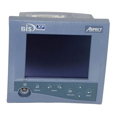
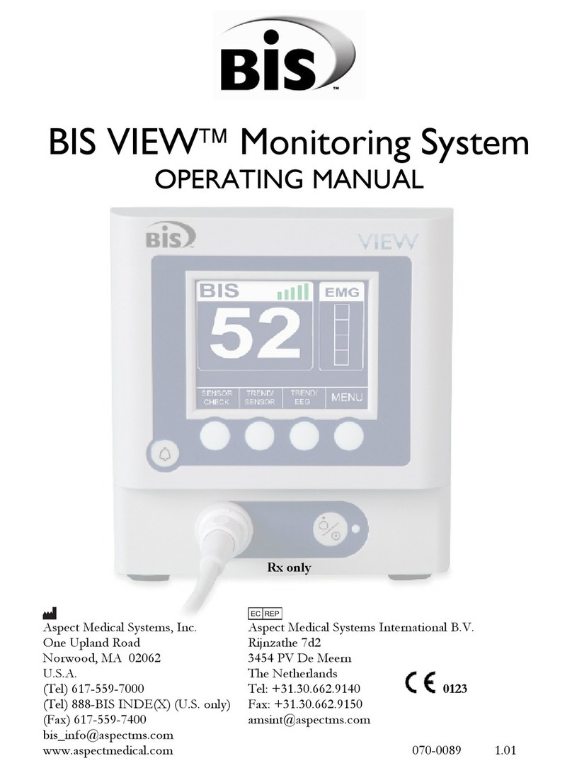
Aspect Medical Systems BISPECTRAL INDEX A-2000 User manual

Aspect Medical Systems
A-2000
TM
BISPECTRAL INDEX
(BIS
) MONITORING SYSTEM
S E R V I C E M A N U A L
Caution:
U.S. Federal law restricts this device
to sale by or on the order of a physician.
© Copyright, 1999, Aspect Medical Systems. All rights reserved. Copying or other reproduction of
this document is prohibited without prior written consent of Aspect Medical Systems.
Aspect Medical Systems, Inc.
2 Vision Drive
Natick, MA 01760-2059
U.S.A.
508-653-0603
800-442-7688
bis_info@aspectms.com
www.aspectms.com
075-0002 1.00

TABLE OF CONTENTS
1. INTRODUCTION .............................................................................. 1-1
1.1 ABOUT THIS MANUAL ....................................................................................1-1
1.2 INTRODUCING THE A-2000 BIS MONITORING SYSTEM.............................1-2
1.2.1 Principal Components ................................................................................1-2
1.2.2 How The A-2000 Works .............................................................................1-3
1.3 INSTRUMENT IDENTIFICATION .....................................................................1-3
1.3.1 A-2000 Monitor ...........................................................................................1-3
1.3.2 A-2000 Digital Signal Converter .................................................................1-3
1.3.3 Software Revision Numbers .......................................................................1-3
1.4 PROPRIETARY INFORMATION AND DEVICES.............................................1-3
2. SAFETY PRECAUTIONS................................................................. 2-1
2.1.1 WARNINGS, CAUTIONS, AND NOTES....................................................2-1
2.1.2 Warnings: ...................................................................................................2-1
2.1.3 Cautions: ....................................................................................................2-3
2.2 KEY TO SYMBOLS ..........................................................................................2-5
3. PRINCIPLES OF OPERATION........................................................ 3-1
3.1 SYSTEM ARCHITECTURE...............................................................................3-1
3.1.1 The Digital Signal Converter (DSC)............................................................3-1
3.1.2 The A-2000 Monitor....................................................................................3-7
3.1.3 A-2000 Printer ............................................................................................3-8
4. PREPARATION FOR USE AND INSTALLATION ........................... 4-1
4.1 ENVIRONMENT ................................................................................................4-1
4.1.1 Shipping and Storage Environment............................................................4-1
4.1.2 Operating Environment...............................................................................4-1
4.1.3 Power Requirements and System Grounding ............................................4-2
4.1.4 Site Preparation..........................................................................................4-2
4.2 INSTRUMENT CONNECTIONS .......................................................................4-3
4.2.1 Digital Signal Converter Connections.........................................................4-3
4.2.2 Power Cord Connections............................................................................4-3
4.2.3 Printer Connector .......................................................................................4-3
4.3 INSTALLATION AND VERIFICATION PROCEDURE .....................................4-4
4.4 REPACKAGING FOR SHIPPING AND STORAGE..........................................4-4

5. PREVENTIVE MAINTENANCE, CARE AND CLEANING ............... 5-1
5.1 CARE AND CLEANING ....................................................................................5-1
5.1.1 Cleaning the Monitor and Digital Signal Converter.....................................5-1
5.1.2 Disinfecting the Monitor and Digital Signal Converter ................................5-1
5.1.3 Cleaning the Monitor Display......................................................................5-1
5.2 ROUTINE MAINTENANCE ...............................................................................5-2
5.2.1 Checking the Battery ..................................................................................5-2
5.2.2 Checking Leakage Current.........................................................................5-2
5.2.3 Monitor System Checkout Procedure.........................................................5-4
5.2.4 DSC Checkout Procedure ..........................................................................5-5
5.2.5 Patient Interface Cable (PIC) Checkout Procedure....................................5-5
6. DIAGNOSTICS AND TROUBLESHOOTING................................... 6-1
6.1 GENERAL TROUBLESHOOTING....................................................................6-1
6.2 THE A-2000 DIAGNOSTIC PROCEDURES.....................................................6-4
6.2.1 Power-Up Diagnostics ................................................................................6-4
6.2.2 Automatic Diagnostics ................................................................................6-8
6.2.3 Manual Diagnostics ..................................................................................6-13
7. DISASSEMBLING AND REASSEMBLING THE A-2000................. 7-1
7.1 REQUIRED TOOLS AND SUPPLIES...............................................................7-2
7.2 THE MONITOR CASE.......................................................................................7-3
7.2.1 Opening the Monitor Case..........................................................................7-3
7.2.2 Closing the Monitor Case ...........................................................................7-3
7.3 THE ELECTRO/LUMINESCENT DISPLAY......................................................7-7
7.3.1 Removing the E/L Display Board................................................................7-7
7.3.2 Reattaching the E/L Display Board.............................................................7-7
7.4 THE FRONT PANEL SWITCH SET..................................................................7-9
7.4.1 Removing the Switch Set ...........................................................................7-9
7.4.2 Installing the New Switch Set .....................................................................7-9
7.5 THE PRINTED CIRCUIT BOARD ASSEMBLY .............................................. 7-11
7.5.1 Removing the Printed Circuit Board assembly.........................................7-11
7.5.2 Installing the Printed Circuit Board Assembly...........................................7-11
7.6 THE MAIN PCB...............................................................................................7-14
7.6.1 Removing the Main PCB ..........................................................................7-14
7.6.2 Installing the Main PCB ............................................................................7-14
7.7 THE POWER SUPPLY PCB ...........................................................................7-19
7.7.1 Removing the Power Supply PCB ............................................................7-19
7.7.2 Installing the Power Supply PCB ..............................................................7-19

7.8 THE BATTERY................................................................................................7-22
7.8.1 Removing the Battery...............................................................................7-22
7.8.2 Installing the Battery .................................................................................7-22
7.9 THE FAN .........................................................................................................7-24
7.9.1 Removing the Fan ....................................................................................7-24
7.9.2 Installing the Fan ......................................................................................7-24
7.10 THE CLAMP SHOE ASSEMBLY....................................................................7-26
7.10.1 Removing the Clamp Shoe Assembly......................................................7-26
7.10.2 Installing the Clamp Shoe Assembly........................................................7-26
7.11 FUSE REPLACEMENT ...................................................................................7-27
8. A-2000 SPECIFICATIONS.............................................................. 8-1
8.1 GENERAL SPECIFICATIONS: .........................................................................8-1
8.1.1 Type of Protection against Electric Shock of the System:..........................8-3
8.1.2 Degree of Protection against Electric Shock of the System: ......................8-3
8.1.3 Degree of Protection against the Ingress of Water: ...................................8-3
8.1.4 Mode of Operation of the System:..............................................................8-3
8.1.5 Classification: .............................................................................................8-3
8.2 OPTIONS AND ACCESSORIES:......................................................................8-3
8.3 Digital Signal Converter (DSC) Connector....................................................8-4
8.4 WARRANTY ......................................................................................................8-5
9. APPENDICES .................................................................................. 9-1
9.1 APPENDIX I - A-2000 PARTS LIST................................................................9-1
9.2 APPENDIX II - SENSOR SIMULATOR - INSTRUCTIONS FOR USE ...........9-2

TABLE OF FIGURES
Figure 1-1 The A-2000 BIS Monitoring System................................................................1-4
Figure 1-2 Rear View of Monitor .....................................................................................1-5
Figure 3-1 The A-2000 System Block Diagram................................................................3-2
Figure 3-2 The A-2000 Signal Flow Diagram ...................................................................3-3
Figure 3-3 The Digital Signal Converter (DSC) ................................................................3-6
Figure 7-1 Opening the Monitor Case............................................................................7-5
Figure 7-2 The E/L Display Cable ...................................................................................7-5
Figure 7-3 The Keypad Cable Tension Flange ...............................................................7-6
Figure 7-4 The Four Mounting Screws............................................................................7-8
Figure 7-5 The Cable Access Port ................................................................................7-10
Figure 7-6 Remove the covering on the back of the new switch set.............................7-10
Figure 7-7 Place rear case assembly face down on a scratch free work surface.........7-13
Figure 7-8 Fan Cable ....................................................................................................7-13
Figure 7-9 Release standoff tab by squeezing with needle-nose pliers ........................7-15
Figure 7-10 The L bracket.............................................................................................7-15
Figure 7-11 Gently pull and flex to separate PCBs .......................................................7-16
Figure 7-12 Line up Interconnect PCB pins to Main PCB socket..................................7-16
Figure 7-13 Align standoffs and push in until standoff tabs snap into place .................7-17
Figure 7-14 Install L bracket by holding long side; short side connects to Main PCB...7-17
Figure 7-15 The L Bracket Installed ..............................................................................7-18
Figure 7-16 Gently flex and pull Power Supply PCB free of pins ..................................7-20
Figure 7-17 Remove four screws on rear of Power Supply PCB ..................................7-20
Figure 7-18 Remove shield from rear of Power Supply PCB........................................7-21
Figure 7-19 Battery and cable .......................................................................................7-23
Figure 7-20 Fan wiring orientation and Clamp Shoe screws ........................................7-25
Figure 7-21 Updated System with 2 Fan Mounting screws and Copper Tape..............7-25
Figure 7-22 Releasing the plastic locking tabs of the fuse holder.................................7-28
Figure 7-23 Re-installing the fuse holder ......................................................................7-28

SECTION I INTRODUCTION
- 1-1 -
SECTION I
1.
INTRODUCTION
1.1
ABOUT THIS MANUAL
This Service Manual contains information necessary to diagnose, troubleshoot and repair
the Aspect Medical Systems A-2000™ BIS
Monitoring System. Also included are
instructions for the unit’s installation, maintenance, care and cleaning. A parts list is
provided in the appendices at the back of the manual.
This manual is intended for Aspect Medical Systems service technicians and/or
authorized Aspect distributors who have been trained by Aspect to perform the service
procedures described within this manual. It assumes prior knowledge and experience
with the internal workings of medical devices and electronics.
Caution:
Refer to the section on disassembling and reassembling before
attempting to service the inside of the A-2000.
Section I provides a functional overview of the A-2000, its principal components, and
instrument identification.
Section II discusses important safety precautions. Before attempting to set up or service
the A-2000, please familiarize yourself with the safety information provided in this section.
Section III describes the A-2000 monitor hardware and how it operates. Included are the
assemblies and parts that make up the monitor and the Digital Signal Converter (DSC).
Section IV provides preparation for use and installation instructions, including
environmental considerations, instrument connections and system setup and check out.
Section V describes normal maintenance, care and cleaning procedures.
Section VI describes the A-2000 diagnostic tools and provides tables to aid in
troubleshooting the system.
Section VII describes the removal and replacement procedure for each subassembly.
Note:
This manual was not designed for repairing the unit to the level of its
individual components (e.g. the chips on the main board). The manual is
intended solely for the troubleshooting and replacement of its
subassembly modules (e.g. the electro-luminescent display and power
supply).
Section VIII contains the A-2000 specifications.
Appendix I contains a list of replaceable parts and subassemblies.
Appendix II contains the Sensor Simulator instructions for use.

SECTION I INTRODUCTION
- 1-2 -
1.2
INTRODUCING THE A-2000 BIS MONITORING SYSTEM
Aspect Medical Systems A-2000 BIS Monitoring System is a user-configurable patient
monitoring system designed to monitor the hypnotic state of the brain based on
acquisition and processing of EEG signals. The A-2000 processes raw EEG signals to
produce a single number, called the Bispectral Index
, or BIS, which correlates to the
patient’s level of hypnosis. It operates from an AC power source of 100V to 240V,
47/63Hz, and provides a minimum 20 minutes of automatic back-up battery power.
The monitor is menu-driven with fixed keys for choosing the options available.
1.2.1
Principal Components
The system is composed of a monitor and a digital signal converter, with a patient
interface cable (PIC), and BIS Sensor.
1.2.1.1 Monitor
The monitor contains the operator control panel, an electro-luminescent display screen,
and connectors for the digital signal converter and printer.
Front Panel Controls:
The [SILENCE] key toggles audible alarms on and off.
The left [←] and right [→] arrow keys are used to enter Review
mode and to scroll data back and forth while in Review mode.
The [MENU/EXIT] key is used to enter and exit the Setup Menu.
In Review mode it will return the user to the main screen. It is
also used to halt certain procedures, such as the sensor check,
and to answer "no" to a question.
The up [↑] and down [↓] arrows are used to move from one
menu selection to another.
The [SELECT] key is used to move between menu selections, to
confirm an entry, and to answer "yes" to a question.

SECTION I INTRODUCTION
- 1-3 -
1.2.1.2 Digital Signal Converter (DSC)
The Digital Signal Converter is about the size of a computer mouse. It contains the EEG
amplifiers and analog filters. The DSC digitizes EEG waveforms for transmission to, and
processing by, the monitor. The DSC’s long flexible Monitor Interface Cable connects to
the front of the monitor, and the shorter “DSC pigtail” cable connects to the Patient
Interface Cable (PIC).
The attachment clip on the DSC is used to secure it in a convenient location near the
patient’s head. The patient connection is accomplished by attaching the Aspect BIS
Sensor to the PIC.
1.2.2
How The A-2000 Works
A detailed description of how the A-2000 works is contained within Section V of the A-
2000 Operating Manual and will not be discussed in this Service Manual. Please refer to
the A-2000 Operating Manual (070-0015) for additional information.
1.3
INSTRUMENT IDENTIFICATION
1.3.1
A-2000 Monitor
Monitor identification information is permanently marked on the rear panel. This
information includes instrument model and serial numbers, power ratings, cautions, and
the Aspect Medical Systems shipping address.
1.3.2
A-2000 Digital Signal Converter
The A-2000 Digital Signal Converter identification information is permanently marked on
the rear panel of the Digital Signal Converter. This information includes instrument model
and serial numbers and cautions.
1.3.3
Software Revision Numbers
Software revision numbers are displayed in the Diagnostic Menu.
1.4
PROPRIETARY INFORMATION AND DEVICES
Information and descriptions contained in this guide are the property of Aspect Medical
Systems and may not be copied, reproduced or distributed without prior written
permission. Portions of the A-2000 design are proprietary and are the subject of patents
and patents pending.

SECTION I INTRODUCTION
- 1-4 -
Figure 1-1 The A-2000 BIS Monitoring System

SECTION I INTRODUCTION
- 1-5 -
Figure 1-2 Rear View of Monitor
Clamp
Shoe
Fuse
Holder
Serial
Port
Potential
Equalization
Terminal

SECTION I INTRODUCTION
- 1-6 -

SECTION II SAFETY PRECAUTIONS
- 2-1 -
SECTION II
2.
SAFETY PRECAUTIONS
INTRODUCTION
Caution:
Carefully read the entire A-2000 Operating Manual before using the monitor in a
clinical setting.
2.1.1
WARNINGS, CAUTIONS, AND NOTES
The terms warning, caution, and note have specific meanings in this manual.
•A WARNING advises against certain actions or situations that could result in personal
injury or death.
•A CAUTION advises against actions or situations that could damage equipment,
produce inaccurate data, or invalidate a procedure, although personal injury is
unlikely.
•A NOTE provides useful information regarding a function or procedure.
KEY TO SYMBOLS
A key to the symbols used on the A-2000 appears at the end of this section.
2.1.2
Warnings:
EXPLOSION HAZARD: DO NOT USE THE A-2000 IN A FLAMMABLE ATMOSPHERE
OR WHERE CONCENTRATIONS OF FLAMMABLE ANESTHETICS MAY OCCUR.
FOR PROPER GROUNDING, THE POWER RECEPTACLE MUST BE A THREE-WIRE
GROUNDED OUTLET. A HOSPITAL GRADE OUTLET IS REQUIRED. NEVER
ADAPT THE THREE-PRONG PLUG FROM THE MONITOR TO FIT A TWO-SLOT
OUTLET. IF THE OUTLET HAS ONLY TWO SLOTS, MAKE SURE THAT IT IS
REPLACED WITH A THREE-SLOT GROUNDED OUTLET BEFORE ATTEMPTING TO
OPERATE THE MONITOR.
IF THE INTEGRITY OF THE EXTERNAL PROTECTIVE EARTH GROUND IS IN
DOUBT, THE A-2000 SHALL BE OPERATED FROM ITS INTERNAL BATTERY
POWER SOURCE ONLY.
GROUND WIRE LEAKAGE CURRENT MUST BE CHECKED WHENEVER
INSTRUMENT CASE IS OPENED BY A QUALIFIED BIOMEDICAL ENGINEERING
TECHNICIAN.
ELECTRICAL SHOCK HAZARD: THE MANUFACTURER’S INSPECTION OF THIS
APPARATUS VERIFIED THAT THE GROUND LEAKAGE CURRENT AND THE
PATIENT SAFETY CURRENT WERE LESS THAN THE SPECIFIED LIMITS
ESTABLISHED BY THE APPLICABLE SAFETY STANDARDS. AS A MATTER OF
SAFE PRACTICE, THE INSTITUTION SHOULD CONDUCT PERIODIC TESTS TO
VERIFY THESE CURRENTS. WHENEVER AN EVENT SUCH AS SPILLAGE OF
BLOOD OR SOLUTIONS OCCURS, RE-TEST BEFORE FURTHER USE.

SECTION II SAFETY PRECAUTIONS
- 2-2 -
UNIVERSAL PRECAUTIONS SHALL BE OBSERVED TO PREVENT CONTACT WITH
BLOOD OR OTHER POTENTIALLY INFECTIOUS MATERIALS. PLACE
CONTAMINATED MATERIALS IN REGULATED WASTE CONTAINER.
DO NOT MIX DISINFECTING SOLUTIONS (e.g. BLEACH AND AMMONIA) AS
HAZARDOUS GASES MAY RESULT.
ELECTRICAL SHOCK HAZARD: DO NOT REMOVE MONITOR COVERS DURING
OPERATION OR WHILE POWER IS CONNECTED TO MONITOR.
FOR CONTINUED PROTECTION AGAINST FIRE OR DAMAGE, ALWAYS REPLACE
OLD FUSE WITH THE SAME FUSE TYPE AND RATING.
ANY PROCEDURES THAT REQUIRE THE REMOVAL OF THE MONITOR’S COVER
AND INTERNAL PARTS SHOULD BE PERFORMED BY A QUALIFIED BIOMEDICAL
ENGINEERING TECHNICIAN. POWER OFF THE UNIT USING THE POWER SWITCH.
UNPLUG THE MONITOR BEFORE DISASSEMBLING/ REASSEMBLING THE
A-2000.
IF METAL COMES IN CONTACT WITH THE TERMINALS ON THE BATTERY, IT
COULD RESULT IN PERMANENT DAMAGE TO THE BATTERY AND IS AN
ELECTRICAL SHOCK HAZARD.
DUE TO THE BATTERY OPERATION POSSIBLE WITH NO AC CONNECTED,
EXTREME CARE MUST BE USED WHEN DISASSEMBLING AND ASSEMBLING THE
A-2000 MONITOR. WITH AC DISCONNECTED AND BATTERY POWER ON, HIGH
VOLTAGE IS PRESENT ON THE E/L DISPLAY AND POWER SUPPLY PCB. DO NOT
ACTIVATE POWER ON SWITCH WITH CASE OPEN!
SHOCK HAZARD: DO NOT ATTEMPT TO DISCONNECT THE POWER CORD WITH
WET HANDS. MAKE CERTAIN THAT YOUR HANDS ARE CLEAN AND DRY BEFORE
TOUCHING THE POWER CORD.
FOR A-2000s USED OUTSIDE OF NORTH AMERICA: A HARMONIZED LINE CORD
WITH CONDUCTORS HAVING A CROSS SECTIONAL AREA GREATER THAN 0.75
MM
2
MUST BE USED.
THE CONDUCTIVE PARTS OF ELECTRODES OR SENSOR AND CONNECTORS,
INCLUDING THE NEUTRAL ELECTRODE, SHOULD NOT CONTACT OTHER
CONDUCTIVE PARTS INCLUDING EARTH.
TO REDUCE THE HAZARD OF BURNS IN THE HIGH FREQUENCY SURGICAL
NEUTRAL ELECTRODE CONNECTION, THE SENSOR OR ELECTRODES SHOULD
NOT BE LOCATED BETWEEN THE SURGICAL SITE AND THE ELECTRO-SURGICAL
UNIT RETURN ELECTRODE.
TO MINIMIZE THE RISK OF PATIENT STRANGULATION, THE PATIENT INTERFACE
CABLE (PIC) MUST BE CAREFULLY PLACED AND SECURED.
BE SURE MONITOR IS MOUNTED SECURELY IN PLACE TO AVOID PERSONAL
INJURY.

SECTION II SAFETY PRECAUTIONS
- 2-3 -
WHEN CONNECTING EXTERNAL EQUIPMENT (e.g. DATA CAPTURE COMPUTER),
THE SYSTEM LEAKAGE CURRENT MUST BE CHECKED AND MUST BE LESS
THAN THE IEC601-1-1 LIMIT.
THE USE OF ACCESSORY EQUIPMENT NOT COMPLYING WITH THE EQUIVALENT
SAFETY REQUIREMENTS OF THIS EQUIPMENT MAY LEAD TO A REDUCED LEVEL
OF SAFETY OF THE RESULTING SYSTEM. CONSIDERATION RELATING TO THE
CHOICE SHALL INCLUDE:
•USE OF THE ACCESSORY IN THE PATIENT VICINITY;
•EVIDENCE THAT THE SAFETY CERTIFICATION OF THE ACCESSORY HAS
BEEN PERFORMED IN ACCORDANCE TO THE APPROPRIATE IEC 601-1
AND/OR IEC 601-1-1 HARMONIZED NATIONAL STANDARD.
FAN WIRE MUST BE POSITIONED AS SHOWN IN FIG. 7-21. INCORRECT ROUTING
OF FAN WIRE MAY RESULT IN A HAZAROUS CONDITION.
2.1.3
Cautions:
U.S. Federal law restricts this device to sale by or on the order of a physician.
Refer to the section on disassembling and reassembling before attempting to
service the inside of the A-2000.
Carefully read the entire A-2000 Operating Manual before using the monitor in a
clinical setting.
Periodically check the battery by operating an A-2000 that has been disconnected
from the wall socket and which has been charging the battery for at least four
hours. After long periods of storage (e.g. > 1 month) it may be necessary to cycle
(discharge, then charge) the battery a few times to get full charge capacity. If the A-
2000 fails to operate reliably from the battery for twenty minutes, battery
replacement is required.
The A-2000 contains an internal Nickel-Metal-Hydride battery. The battery must be
removed by a qualified service technician and disposed of or recycled in
accordance with the national laws of the country. Contact Aspect Medical Systems,
Inc. or the local distributor for a replacement battery.
A burned out fuse usually indicates a serious problem with the electrical system of
the A-2000 unit. Call service before attempting to remove and replace a fuse.
If metal comes in contact with the battery terminals, permanent damage to the
battery and other connecting parts could result.
Do not autoclave the Digital Signal Converter or Monitor. Autoclaving will seriously
damage both components.
Do not submerge.
Do not block fan output. Keep at least three full inches of unobstructed space
between rear of instrument and wall and other instruments. Do not allow other
instruments to block airflow. Do not block ventilation inlet holes on the underside
of monitor.

SECTION II SAFETY PRECAUTIONS
- 2-4 -
Do not open Digital Signal Converter for any reason. The seal to prevent liquids
from entering the Digital Signal Converter may be damaged if opened. Service or
repairs must be performed only by qualified biomedical technicians.
The A-2000 has been designed to operate with a disposable BIS Sensor. The
sensor is a silver/silver chloride electrode array that utilizes Aspect’s patented
Zipprep
technology and uses a proprietary connector. Use of incorrect types of
electrodes may result in intermittent loss of signal or poor signal quality.
Continuous impedance checking may need to be disabled if the 1 nanoampere 128
Hz impedance check signal interferes with other equipment, e.g., evoked potential
monitors.
VERY IMPORTANT! Use only the Loctite number specified. Using the incorrect
Loctite will damage plastic components.
Use only the parts and tools specified. Use of any others may damage the
instrument.
Failure to position E/L Display screen gasket properly may result in a monitor that
will allow fluid to leak in when the display is cleaned.
Replace battery only with same type of approved battery. Use of non-approved
battery may result in incorrect operation or damage to the monitor.
A-2000 is a trademark and Bispectral Index, BIS and Zipprep are registered trademarks
of Aspect Medical Systems, Inc.

SECTION II SAFETY PRECAUTIONS
- 2-5 -
2.2
KEY TO SYMBOLS
ON (power; connection to the mains)
OFF (power; disconnection from the mains)
Audible Alarm Silenced
Operating on Battery
Type BF Equipment
Attention, Consult Accompanying Documents
J1
Attention, J1 RS-232 Serial Port, Consult
Accompanying Documents
J2
Attention, J2 Printer Port, Consult Accompanying
Documents

SECTION II SAFETY PRECAUTIONS
- 2-6 -
Fuse, Replace only with same Type and Rating
Equipotential
Alternating Current
Dangerous Voltage
Protective Earth (ground)
Storage Temperature Limits

SECTION III PRINCIPLES OF OPERATION
- 3-1 -
SECTION III
3.
PRINCIPLES OF OPERATION
The A-2000 BIS Monitoring System consists of:
•The BIS monitor with built-in battery backup and detachable power cord
•The Digital Signal Converter (DSC)
•Aspect’s BIS Sensor Patient Interface Cable (PIC) and BIS Sensor
This section describes the architecture of the A-2000 monitor and DSC and how their
constituent parts interact.
3.1
SYSTEM ARCHITECTURE
Hardware is divided into two main components: the monitor and the digital signal
converter (DSC). The A-2000 monitor contains the circuits for digitally processing the
EEG data, computing the processed parameters, and displaying the waveforms and
processed parameters. The circuits to acquire and digitize the EEG signals reside in the
Digital Signal Converter (DSC).
The monitor also contains the circuits for powering the monitor, DSC, and companion
printer. Integral to these circuits is a battery backup. Printer function is not available
while on battery backup.
A block diagram depicting the monitor subassemblies appears in Figure 3-1. A signal flow
diagram appears in Figure 3-2.
After passing through input protection circuits in the DSC, the EEG signals are differentially
amplified and filtered to remove DC and high frequency components. The signals are
digitized by separate one bit sigma-delta analog to digital converters. The outputs from the
converters are multiplexed onto the DSC communications line and de-multiplexed in the
monitor prior to being fed to the Digital Signal Processor (DSP). The DSP filters the signals
and computes the processed variables. The results are passed to the host CPU for display.
3.1.1
The Digital Signal Converter (DSC)
The DSC contains the inputs, amplifiers, and digitizers for two channels of EEG. It has a
single point connection that connects via a Patient Interface Cable (PIC) to a BIS Sensor.
The A-2000 is designed to process one channel using the BIS Sensor, the A-2000 and DSC
hardware is capable of two channels. The sensor and PIC contains circuits for identifying
them to the monitor. This permits the monitor to configure automatically.
The DSC constantly monitors the combined source impedance at its inputs, and also has
facility for measuring the individual impedance of the channel and ground electrodes. There
are circuits for injecting self-test voltages into the amplifier inputs.

SECTION III PRINCIPLES OF OPERATION
- 3-2 -
Figure 3-1 The A-2000 System Block Diagram

SECTION III PRINCIPLES OF OPERATION
- 3-3 -
Figure 3-2 The A-2000 Signal Flow Diagram
Table of contents
Other Aspect Medical Systems Medical Equipment manuals
Popular Medical Equipment manuals by other brands

B. Braun
B. Braun Aesculap Instructions for use/Technical description

Care Fusion
Care Fusion Alaris Propofol-Paedfusor Directions for use

Gamma+
Gamma+ CADIAX compact Series operating instructions

Smith & Nephew
Smith & Nephew JOURNEY II BCS manual

B. Braun
B. Braun Infusomat fmS Instructions for use

Contec
Contec CMS50DL user manual