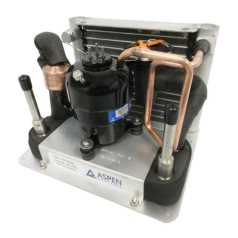
Aspen LCM-Twin T38 Owner's manual

24 St. Martin Dr.
Marlborough, MA 01752
Installation and Operation Instructions
LCM-Twin T38
FP00066, FP00102
Installations Notes
Date of Purchase
Date of Installation
Installer
Model Number
Serial Number

OM00017 Rev B, FP00066, FP00102 Operation Manual –March 24, 2023 Page 2of 10
Contents
System Information ......................................................................................................................................3
Safety ............................................................................................................................................................3
General Operation ........................................................................................................................................4
Environmental...........................................................................................................................................4
Condenser Fans.........................................................................................................................................4
Fluid Connections......................................................................................................................................4
Mounting...................................................................................................................................................4
Power Supply –FP00066 ONLY.................................................................................................................6
Power Supply –FP00102 ONLY.................................................................................................................6
Thermal Switch .........................................................................................................................................6
Compressor Control..................................................................................................................................6
Performance .................................................................................................................................................7
Maintenance.................................................................................................................................................8
Customer Service ..........................................................................................................................................8
Commercial Product Warranty .................................................................................................................8
Warranty Repairs......................................................................................................................................9
Technical Support ...................................................................................................................................10
Aspen Contact Information.....................................................................................................................10
APPENDIX....................................................................................................................................................10

OM00017 Rev B, FP00066, FP00102 Operation Manual –March 24, 2023 Page 3of 10
System Information
The T-38 Liquid Chiller Module (LCM-1400) is a chassis mounted cooling system. The LCM is the core of a
variable speed, vapor-compression chiller. When properly installed, the LCM uses vapor compressor
technology to cool a circulating coolant. The LCM consists of a compressor (with drive board),
condenser, over-pressure valve, filter dryer, expansion valve, evaporator, and fans.
Figure 1: LCM (FP00066, FP00102) Assembly (drive board and cable not shown)
Safety
The LCM contains Tetrafluoroethane (R-134a) as a refrigerant. R-134a is an approved long-term
replacement for CFC-based refrigerants and an approved ozone depleting substance (ODS) alternative.
In the event that the LCM is damaged, general work clothing, leather gloves, and eye protection should
be worn to prevent exposure to refrigerants. The LCM also contains Polyalkylene glycol (PAG) oil, which
is used by the compressor. Contact Aspen for the MSDS for either of these internal fluids.
Precautions relating to the personnel hazards regarding contact with this substance should be outlined
in training and technical manuals.
Disposal of R-134a must comply with federal, state, and local disposal or discharge laws.
WARNING! R-134A is subject to U.S. Environmental Protection Agency Clean Air Act
Regulations Section 608 in 40 CFR Part 82 regarding refrigerant recycling, therefore the
refrigerant must be evacuated from the LCM prior to disposal of the assembly.
CAUTION! Skin contact with refrigerant may cause frostbite.
CAUTION! The compressor, discharge copper line, and condenser may get extremely
hot. Do not touch during operation

OM00017 Rev B, FP00066, FP00102 Operation Manual –March 24, 2023 Page 4of 10
General Operation
Environmental
Coolant Water, Glycol/Water Mixtures (contact Aspen for use of other coolants)
Ambient (Operation) -20°C to 50°C (-4°F –122°F)
Ambient (Storage) -20°C to 50°C (-4°F –122°F)
Weight 5.4 kg (12 lb)
Size 22.6 x 33.7 x 21.3 cm (9.0 x 13.26 x 8.4 in)
Condenser Fans
To operate properly, airflow must be provided to the condenser prior to turning the compressor on.
Two fans are attached to the condenser, which requires a 48 VDC (FP00066) or 24 VDC (FP00102) power
supply. The provided fans each generates 138 cfm (without restriction). Aspen Systems does NOT
recommend using the available voltage output on the compressor drive board to operate the fan. Please
connect the fan directly to a 48 VDC supply (FP00066) or 24 VDC supply (FP00102). See Figure 2 for
airflow direction.
Fluid Connections
The LCM terminates with 3/8-inch John Guest push-to-connect (Speedfit) fittings. The user must adapt
their cooling loop to these fittings. These fittings are rated to 140 psig with suitable tubing.
Provided Fittings: John Guest Superseal Speedfit: SI031212S
A customer supplied coolant pump must be used to generate coolant flow across the evaporator. In
order to achieve the maximum performance from the system, proper insulation of the coolant lines may
be required.
Mounting
The LCM is supplied on an 0.063-inch-thick aluminum base plate. There are four #10 clearance holes
(0.221-inch diameter) that can be used to hold down the LCM. See drawing (Figure 2) for hole locations
and full outer dimensions. Insulation and screw heads may protrude beyond the defined overall
geometry. Contact Aspen directly if a solid model is required.
WARNING! The system must be used with the supplied fans and the airflow path must not be
obstructed. Obstruction of the airflow path may cause the system to overheat and damage the
compressor.
CAUTION! When using a water-based coolant, care must be taken to avoid freezing in the
evaporator. THE LCM IS CAPABLE OF FREEZING WATER WITHIN THE EVAPORATOR IN LESS
THAN 1 MINUTE IF WATER FLOW STOPS OR SLOWS WHILE THE LCM CONTINUES TO RUN.
Freezing the evaporator could rupture the evaporator causing a water and/or refrigerant leak.

OM00017 Rev B, FP00066, FP00102 Operation Manual –March 24, 2023 Page 5of 10
Figure 2: LCM Dimensional Drawing - Note all dimensions are in inches
Airflow direction
Airflow direction

OM00017 Rev B, FP00066, FP00102 Operation Manual –March 24, 2023 Page 6of 10
Power Supply –FP00066 ONLY
The CB00067 motor drive board PCB shipped with the LCM is a 48 VDC unit. The operating voltage range
is 43 VDC –50 VDC. The LCM may draw up to 10.5 A of current during normal operation (compressor
and fans combined). Aspen recommends at least 16 AWG wire for the power supply to the compressor
drive board with an in-line 10 A fuse (see Appendix page 3)
Power Supply –FP00102 ONLY
The CB00066 motor drive board PCB shipped with the LCM is a 24 VDC unit. The operating voltage range
is 22 VDC –30 VDC. The LCM may draw up to 16 A of current during normal operation (compressor and
fans combined). Aspen recommends at least 12 AWG wire for the power supply to the compressor drive
board with an in-line 15 A fuse (see Appendix page 3).
Thermal Switch
The LCM is provided with a thermal switch attached to the top of the compressor. This thermal switch
provides protection for the compressor to prevent overheating in the case of a failure condition (e.g.
blocked air, failed fan, elevated ambient temperature, etc). This thermal switch shall be connected to
the overheat tab (TB11) and the ground tab (TB9).
Compressor Control
Please refer to the Universal Low Noise Sinusoidal BLDC Drive manual (see appendix) for detailed
wiring and functionality of the drive board. Use the included three-conductor harness to connect the
drive to the compressor.
The motor drive board is a variable speed drive. This allows the cooling capacity of the system to be
adjusted by increasing or decreasing the compressor speed. The compressor drive board can use one of
four different speed input signals: 0 –5 V analog voltage (factory default), 0 –10 VDC analog voltage, 4 –
20 mA, and frequency (see Appendix pages 5 - 6). The firmware has a minimum speed of 1200 RPM
(condition-dependent) and a maximum speed of 6500 RPM.
CAUTION! The LCM must be operated in the vertical orientation. Operation of the
system at an orientation of >10° from vertical may result in reduced system capacity.
Operation at >30° from vertical will reduce capacity and may damage the compressor.
CAUTION! Operating the LCM outside the voltage range will void the system warranty.
CAUTION! Operating the LCM on battery power will void the system warranty.
CAUTION! Operating the LCM outside the voltage range will void the system warranty.
CAUTION! Operating the LCM on battery power will void the system warranty.
CAUTION! Operating the LCM without the thermal switch connected will void the system warranty.

OM00017 Rev B, FP00066, FP00102 Operation Manual –March 24, 2023 Page 7of 10
Note: In some conditions, the compressor will reach its nominal current limit. This condition is most
likely in warmer ambient conditions. A 24V compressor will limit at (15 A), which will cause the
compressor to reduce speed until the current drops to 15 A. The 48V compressor will limit at 10A and
will lower compressor speed until the current reaches 10A.
Figure 3 –FP00102 & FP00066 Drive-Board Jumper Configuration
The FP00102/ FP00066 drive-board default jumper configuration is shown in the image above. More
information about jumper settings and the driveboard functionality is located in the appendix.
Performance
The performance curve below (Figure 4) defines the performance of the LCM. The data shown below is
derived using 2 L/min water flow and a 30% glycol solution for subzero operation.
CAUTION! Aspen recommends the following operating sequence: (1) power on the drive board, (2)
ground the enable line (3) apply a speed signal to run the compressor. Applying power to the drive
board while the enable line is grounded may result in high in-rush currents
CAUTION! Power and phase wires are not intended for repeated connection and disconnection.
Multiple connections and disconnections of these wires to the board can result in poor electrical
contact, leading to cable overheating and system damage.

OM00017 Rev B, FP00066, FP00102 Operation Manual –March 24, 2023 Page 8of 10
Figure 4: LCM Performance Map
Maintenance
The LCM is a sealed unit and does not require regular maintenance to operate. Depending on
environmental conditions the condenser fins could become fouled with dust and debris. A fouled
condenser will cause the LCM to operate inefficiently and potentially over-heat and shut down. To clean
the condenser, follow the steps below. All work should be performed while wearing safety glasses and
ear protection with the LCM powered off.
1. Use a damp (water), lint free towel and wipe the inner face of the condenser. Be careful not to
bend or damage any of the fins.
2. Alternatively, the user may remove the fan and air may be blown through the condenser to
remove any dust. Use a compressed air source regulated to between 50 and 100 psi and keep
the nozzle at least 2 inches away from the condenser face. Be sure to reattach the fan and fan
guard when finished cleaning the coils.
Customer Service
Commercial Product Warranty
Aspen System LLC (hereinafter referred to as “Aspen”), warrants to the original purchaser that products
sold shall be free from defects in material and workmanship for the warranty period not to exceed one
year from the date of shipment. If buyer claims that a product violates such warranty, Aspen, upon
notice promptly given, will either examine the product at buyer’s site, or issue shipping instructions for
return to Aspen at buyer’s expense, transportation charges prepaid.
CAUTION! Directing airflow at the condenser fins at an angle may result in
bending/damage of the LCM fins, resulting in decreased condenser performance.

OM00017 Rev B, FP00066, FP00102 Operation Manual –March 24, 2023 Page 9of 10
Aspen’s sole obligation under its warranty shall be, at its option, to repair, replace or refund the price of
any product thereof which is proved to violate such warranty. In no event, whether based on contract,
indemnity, warranty, tort (including negligence), strict liability or otherwise, shall Aspen be liable to the
buyer for special, indirect, incidental or consequential damages whatsoever including, without
limitation, loss of profit or revenue.
The above warranty is buyer’s exclusive remedy and Aspen hereby expressly disclaims all other
warranties, express or implied, including the implied warranty of merchantability and the implied
warranty of fitness for a particular purpose. The foregoing shall constitute the sole remedy of the buyer
and the sole liability of Aspen.
This Limited Warranty shall not apply to any product or component thereof which has been repaired or
altered outside of Aspen’s factory in any manner so as, in Aspen’s sole judgment, to affect its
serviceability, or to any product that has been subject to alteration, accident, misuse, abuse, neglect or
normal wear. The Limited Warranty shall not apply to products which have been assembled or installed
or used in a manner contrary to Aspen’s printed instructions, or due to failure to follow Aspen printed
instructions for operation and maintenance. This product is designed and intended to be installed and
operated in an enclosure that is sealed from the ambient environment. Exposure to water leakage into
the enclosure and/or excessive condensation from exposure to humid ambient air during operation will
void this warranty. Any technical assistance provided by Aspen’s personnel or representatives in system
design is construed to be a proposal and not a recommendation. The responsibility for determining
feasibility rests with the user and should be subject to test. Only the terms expressed in this Limited
Warranty shall apply and no distributor, corporation or individual is authorized to amend, modify or
extend this warranty in any way on resale.
Warranty Repairs
Any product returned and found to be under warranty will be repaired or replaced at the discretion of
Aspen Systems, LLC. Depending on the circumstances of the problem, it may be deemed necessary to
return the products to Aspen Systems. for repair. In order to return the product for repair, please
contact Aspen Systems via email, telephone, or through the Aspen Systems’ website (see Contact
Information)

OM00017 Rev B, FP00066, FP00102 Operation Manual –March 24, 2023 Page 10 of 10
Technical Support
Technical Support is available from Aspen Systems from 8:00 AM to 5:00 PM (EST) Monday through
Friday via phone or email (see contact information). Technical support can also be requested on-line. To
expedite assistance for problems, be able to provide the following information:
•Your name, phone number, company, division and city.
•Product number, serial number and revision (located on the LCM evaporator bracket).
•A detailed description of your problem.
Aspen Contact Information
Email: info@aspensystems.com
Phone: 508-281-5322
Website: http://aspensystems.com/contact
APPENDIX
See following pages for appendix

Aspen Compressor, LLC
24 St. Martin Drive, Marlborough, MA 01752 508-281-5322 508-281-5323
web: www.aspencompressor.com email: info@aspencompressor.com
Feb, 2023 Rev. D 1 of 15
ASPEN COMPRESSOR
Universal Low Noise Sinusoidal BLDC Drive
Operating Instructions
Aspen’s Universal Low Noise Sinusoidal BLDC Drive can be operated in 2 distinct modes. This allows it the
ability to seamlessly replace all existing Aspen drives, as well as offer significant compressor noise
reduction, lower compressor operational speeds and several different input types for speed control. It also
has the ability to operate any compressor in the Aspen Compressor line.
Drive Mode Jumper Configuration –
Mode 1 operation is a direct replacement for the 1501017, 1501018, 1501029, & 1501031 High
Performance BLDC drive originally used on all A and Q series compressors. In this mode the drive will
behave as a direct replacement for the 1501017/1501018/1501029/1501031 High Performance BLDC drive.
To operate in this mode, install a jumper as shown in the picture below. While this mode replicates the
performance of the drives listed above, it does not offer the additional low noise, lower operating speeds
and additional speed input types that are available when operating in Mode 2. However, there is a
provision within this mode to operate taking advantage of the quiet sinusoidal mode only, without the
other added functions of operating in Mode 2. See Note 1 on page 9 for information regarding this.
Drive Mode Jumper
JP2
Jumper
Mode 1
1501017, 1501018, 1501029, & 1501031
(Direct Replacement)
Installed As
Shown

Aspen Compressor, LLC
24 St. Martin Drive, Marlborough, MA 01752 508-281-5322 508-281-5323
web: www.aspencompressor.com email: info@aspencompressor.com
Feb, 2023 Rev. D 2 of 15
ASPEN COMPRESSOR
Universal Low Noise Sinusoidal BLDC Drive
Mode 2 operation is a Universal Quiet Sinusoidal drive for all single and twin cylinder compressor models.
In this mode, the drive offers ultra-quiet sinusoidal compressor operation as well as enhanced lower
operating speeds and additional choices for speed input.
Drive Mode Jumper
JP2
Jumper
Mode 2
Universal Quiet Sinusoidal
Not Installed

Aspen Compressor, LLC
24 St. Martin Drive, Marlborough, MA 01752 508-281-5322 508-281-5323
web: www.aspencompressor.com email: info@aspencompressor.com
Feb, 2023 Rev. D 3 of 15
ASPEN COMPRESSOR
Universal Low Noise Sinusoidal BLDC Drive
Connections
Power Supply Input (TB5 & TB6)
Aspen’s Universal Sinusoidal Low Noise Drive is available in 12, 24 and 48 volts.
The use of adequate wire gage and an inline fuse for short circuit protection is required for safe reliable
operation. The table below shows the recommended wire gage and input fuse size for each of the Aspen
drives.
Drive
Board
Operating
Voltage Range
Recommend
Wire AWG
Recommended Fuse
12 Volt
11-16 Volts
12
15A
(Littlefuse 0312015)
24 Volt
20-30 Volts
12
10A or 15A
(Littlefuse 0312010 / 0312015)
48 Volt
43-60 Volts
16
8A or 10A
(Littlefuse 0312008 / 0312010)
(TB7) Condenser Fan (+)
(TB5) Power In (-)
(TB6) Power In (+)
(TB8) Condenser Fan (-)
(TB11) Compressor Overheat
(TB9) Ground (-)
(TB10) +5v
(TB12) Compressor Enable
(TB13) Compressor Current Out
(TB14) Compressor Speed Input
(TB15) Compressor Speed Low
(TB16) Compressor Status

Aspen Compressor, LLC
24 St. Martin Drive, Marlborough, MA 01752 508-281-5322 508-281-5323
web: www.aspencompressor.com email: info@aspencompressor.com
Feb, 2023 Rev. D 4 of 15
ASPEN COMPRESSOR
Universal Low Noise Sinusoidal BLDC Drive
Additionally, the condenser fan output should also be fused if it is to be used. Recommended fuse size for
the condenser fan output are as follows:
1. Condenser Fan Output (TB7 & TB8)
An output has been provided for running condenser fan(s) from the Aspen drive. The voltage of this output
will be equivalent to the DC input voltage provided to the board. The power to the condenser fan is
enabled 10 seconds after the drive starts the compressor. Therefore, when the compressor is off, the
power to the condenser fan(s) is off. When the compressor is signaled to run, the power to the condenser
fan(s) will be enabled 10 seconds after the compressor has started running. This 10 second delay is
intentional and is meant to reduce the total amount of inrush current when the compressor starts. The
connections to the condenser fan outputs are two .250” faston tabs. The condenser fan output should be
limited to a maximum of 5 amps on 12/24 volts boards and 3 amps on 48 volt boards. When in use, the
outputs require an inline fuse for safe operation. Install the appropriate inline fuse per the table above.
2. Ground (TB9)
The ground tab is for connecting both the compressor enable and compressor over temp connections to.
Both the compressor enable and the compressor overheat connections must be connected to ground in
order for the compressor to operate. The connection to the ground is a .187” faston tab.
3. +5V (TB10)
The +5v tab is provided to give the user the ability to provide a low voltage speed signal input without the
use of an additional power supply. The 5 volts can be wired directly to the speed input tab, which will cause
the compressor to operate at full speed, or can be wired to a 20k potentiometer to allow the user to vary
the voltage to the speed input tab and vary the speed of the compressor. The connection to the +5v is a
.187” faston tab.
4. Compressor Overheat (TB11)
In order for the compressor to operate, the overheat tab connection must be connected to the thermal
safety switch, which is then connected to ground. When used in conjunction with the thermal switch, the
drive will shut the compressor off when the thermal switch indicates that the compressor has overheated.
Once this has occurred, the board will flash the red LED a sequence of 16 flashes to indicate that the
compressor has overheated. To restart the compressor, the thermal switch must reset and the user must
either cycle the main power on the drive board or momentarily disconnect the enable wire from ground.
The connection to the compressor overheat is a .187” faston tab.
Drive Board
Operating
Voltage Range
Condenser Fan
Output Fuse
Recommended Fuse
12 Volt
11-16 Volts
6
6A
(Littlefuse 0312006)
24 Volt
20-30 Volts
6
6A
(Littlefuse 0312006)
48 Volt
43-60 Volts
4
4A
(Littlefuse 0312004)

Aspen Compressor, LLC
24 St. Martin Drive, Marlborough, MA 01752 508-281-5322 508-281-5323
web: www.aspencompressor.com email: info@aspencompressor.com
Feb, 2023 Rev. D 5 of 15
ASPEN COMPRESSOR
Universal Low Noise Sinusoidal BLDC Drive
5. Compressor Enable (TB12)
In order for the compressor to operate, the compressor enable tab connection must be connected to
ground. This connection can also be wired through a thermostat and then to ground to cycle the
compressor on and off via a thermostat. The connection to the compressor enable is a .187” faston tab.
6. Compressor Current Out (TB13)
The drive is equipped with a current out connection to allow the user to monitor the current consumption
of the compressor. The current out connection puts out a voltage that correlates to the current being used
by the compressor only and not the condenser fans if they are so attached. The correlation is .1 volts per
amp, so if the compressor is using 5 amps of power, the voltage measure on the current out tab will be .5
volts. The connection to the compressor current out is a .187” faston tab.
7. Compressor Speed Input (TB14) Mode 1 Operation Only
The connection to the compressor speed input is a .187” faston tab.
In Mode 1 operation, a voltage must be applied to the compressor speed input tab in order for the
compressor to operate. The compressor speed input accepts a 0-5 vdc analog voltage signal and will
regulate the speed of the compressor automatically with respect to this input voltage per the table below.
8. Compressor Speed Input (TB14) Mode 2 Operation Only
Enhanced Compressor Speed Range - When operating in Mode 2, the drive has the ability to control speed
from 1200-6500 RPM’s on T & H series twin cylinder compressors and 1400-6500 RPM’s on A & Q series
single cylinder compressors. In each instance, the compressor will only reduce speed below 2000 RPM’s
when the compressor current is below a stable operating threshold. This is done to increase operational
reliability and prevent the compressor from stalling at very low operating speeds. There are 4 different
options for speed input when operating in Mode 2. The charts and information below show the different
input types and speed scaling relationships for both single and twin cylinder compressors. Jumper settings
for these options can be found at the end of this section.
Compressor Speed Input / Mode 1 Operation
1.4 & 1.9 Q and A Series Compressors
Input
RPM
Option 1
0-5 VDC
Turn Off
2000
~0.65
Turn On
2200
~0.80
Full Speed
6500
4.5

Aspen Compressor, LLC
24 St. Martin Drive, Marlborough, MA 01752 508-281-5322 508-281-5323
web: www.aspencompressor.com email: info@aspencompressor.com
Feb, 2023 Rev. D 6 of 15
ASPEN COMPRESSOR
Universal Low Noise Sinusoidal BLDC Drive
Option 1 (0-5v input / Mode 2 Operation Only) - The compressor speed input accepts a 0-5 VDC
analog voltage signal and will regulate the speed of the compressor automatically with respect to this
input voltage. There will be a linear increase in speed based on this input voltage. The charts above
show the different inputs and speed scaling relationships for both single and twin cylinder
compressors when using this option.
Option 2 (0-10 v input / Mode 2 Operation Only) - The compressor speed input accepts a 0-10 VDC
analog voltage signal and will regulate the speed of the compressor automatically with respect to this
input voltage. There will be a linear increase in speed based on this input voltage. The charts above
show the different inputs and speed scaling relationships for both single and twin cylinder
compressors when using this option.
Option 3 (4-20mA input / Mode 2 Operation Only) - The compressor speed input accepts a 4-20mA
input signal and will regulate the speed of the compressor automatically with respect to this input
signal. There will be a linear increase in speed based on this input signal. The charts above show the
different inputs and speed scaling relationships for both single and twin cylinder compressors when
using this option.
Option 4 (Frequency input / Mode 2 Operation Only) -.The compressor speed input accepts a
frequency input signal and will regulate the speed of the compressor automatically with respect to
this input signal. The frequency signal should be a 5 VDC, 50% duty cycle, square wave. There will be
a linear increase in speed based on this input signal. The charts above show the different inputs and
speed scaling relationships for both single and twin cylinder compressors when using this option.
9. Compressor Speed Low (TB15)
This tab should be used when a secondary power supply is being used to supply power for speed control
and the user wants the secondary supply to be isolated from the power supply being used to power the
Compressor Speed Input / Mode 2 Operation
1.4cc & 1.9cc Q and A Series Compressors
Input
RPM
Option 1
0-5VDC
Option 2
0-10VDC
Option 3
4-20mA
Option 4
Frequency hz
Drop Out
1400
~0.65
~1.3
~6.1
~33
Pick Up
1600
~0.80
~1.6
~6.6
~39
Full Speed
6500
4.50
9.00
18.6
180
Compressor Speed Input / Mode 2 Operation
2.8cc & 3.8cc Twin Series Compressors
Input
RPM
Option 1
0-5v
Option 2
0-10v
Option 3
4-20mA
Option 4
Frequency
Drop Out
1200
~0.65
~1.3
~6.1
~33
Pick Up
1400
~0.80
~1.6
~6.6
~39
Full Speed
6500
4.5
9.0
18.6
180

Aspen Compressor, LLC
24 St. Martin Drive, Marlborough, MA 01752 508-281-5322 508-281-5323
web: www.aspencompressor.com email: info@aspencompressor.com
Feb, 2023 Rev. D 7 of 15
ASPEN COMPRESSOR
Universal Low Noise Sinusoidal BLDC Drive
drive. In this case the factory installed jumper should be removed. This will decouple the board ground
reference from the speed signal to allow for minor voltage differences between the power supply
grounds. The common mode range is -1.0 to +1.0V. The secondary power supply for speed control can
then be wired between the speed input and speed low connections to vary compressor speed. The
connection to the compressor speed low is a .187” faston tab. See the jumper configuration table at the
end of this section for details.
10. Compressor Status (TB16)
This tab is available to monitor the normal operation of the compressor. When a speed signal is being sent
to the drive and the compressor is operating normally, there will be no voltage on this connection.
However, if a speed signal is present and the compressor enable is satisfied but the compressor is not
running, 5 volts will be present on this tab. This 5v signal can be monitored to alert the end user that there
is a problem with the system and that the compressor is not running.
Additional Board Functions
1. Compressor Start Delay –The Aspen drive has the ability to delay the compressor start in situations
where starting may be difficult due to an unbalanced system. The logic behind the delay is based on a
minimum off time for the compressor and can be enabled by installing jumpers per the table at the end
of this section. When activated the controller keeps track of how long the compressor has been turned
off before trying to restart. If the compressor has been off for the minimum amount of time set by the
dip switch when there is a call to restart, it will start immediately. If the minimum amount of time has
not passed, the compressor will wait until the minimum time has been reached before attempting to
start.
2. Board Overheat –The Aspen drive has an onboard thermistor that enables the drive to prevent itself
from overheating. When the board detects that it has overheated, the drive will stop the compressor
and emit a series of 8 flashes on the red LED.
3. Automatic Current Limiting –The Aspen drive has the ability to regulate the amount of current being
used by the compressor. The 12v & 24v drives have a user selectable 10 or 15 Amp limit. The 48V has a
user selectable 8 or 10 Amp limit. The drive will automatically monitor the current consumption of the
compressor. If the compressor motor begins to draw more than the maximum set current, the drive
will automatically decrease the speed of the compressor in an effort to reduce the current being used.
When this happens, the red LED will illuminate as well as the green to inform the operator that the
compressor is operating in this mode. If the speed of the compressor continues to be reduced due to
overcurrent, the compressor will eventually stall and flash the red LED continuously to allow the user to
know that the compressor has stalled from excessive current draw or a lock rotor condition. It should
be noted that the automatic current limit only reduces the current used by the compressor motor and
does not account for any current that may be drawn by the use of the condenser fan output.

Aspen Compressor, LLC
24 St. Martin Drive, Marlborough, MA 01752 508-281-5322 508-281-5323
web: www.aspencompressor.com email: info@aspencompressor.com
Feb, 2023 Rev. D 8 of 15
ASPEN COMPRESSOR
Universal Low Noise Sinusoidal BLDC Drive
4. Low Speed Stall Protection –The Aspen drive allows the compressor a speed range of 1200-6500
RPM’s. The drive will only allow the compressor to operate at speeds below 2000 rpm’s when the
current is below a reliable operating threshold. If the current is not below a reliable operating
threshold, the compressor will increase speed automatically between 1200 and 2000 to maintain
operational reliability at the lowest possible speed, while preventing the compressor from stalling.
When this happens, the red led will illuminate as well as the green to inform the operator that the
compressor is operating in this mode.
5. Lock Rotor Protection - The Aspen drive has the ability to detect if the compressor is not running due
to a lock rotor condition. After the drive has made several unsuccessful attempts to start the
compressor, the drive will stop attempting to start the compressor and flash the red LED continuously
to allow the user to know that the compressor has stalled from excessive current draw or a lock rotor
condition.
6. Error Clearing –The drive can go in to error mode for several reasons in which case the compressor will
stop running. To clear the error and restart the compressor, the enable wire must be disconnected and
then reconnected to ground. For a list of error conditions, see the error code table at the end of this
document.
7. Multiple Stall Over Time –The Aspen drive monitors the compressor for repeated stalling due to
conditions that may occur such as condenser fan failure or continuous liquid flooding. If the
compressors is stalling repeatedly, the drive will stop the compressor and flash the red LED
continuously to allow the user to know that the compressor has been turned off due to a multiple stall
over time condition.

Aspen Compressor, LLC
24 St. Martin Drive, Marlborough, MA 01752 508-281-5322 508-281-5323
web: www.aspencompressor.com email: info@aspencompressor.com
Feb, 2023 Rev. D 9 of 15
ASPEN COMPRESSOR
Universal Low Noise Sinusoidal BLDC Drive
Mode 1
Selection Jumper Settings
Option Jumpers For Mode 1 Operation
Use This Table When Operating In Mode 1
Jumper
Position
Function
Installed
Not Installed
6
Speed Low
Isolation
Not Isolated
(Factory Default)
Isolated
5
Control
Type
Sin Mode
See Note 1 Below
Trap Mode
See Note 1 Below
4
Current
Limit
10 Amps / 12 & 24v
8 Amps / 48v
15 Amps / 12 & 24v
10 Amps / 48v
3
Start Delay
See table below
See table below
2
Start Delay
See table below
See table below
1
Voltage
Consult Factory
Consult Factory
Start Delay
Jumpers To Install
Off
None
(Factory Default)
30 sec
Location 2
60 sec
Location 3
120 sec
Location 2 & 3
**Note 1**
Option 5
Trap Mode (jumper not installed)
In this configuration, the drive will operate in
trapezoidal motor control mode and will behave
exactly like preceding drive models 1501017,
1501018, 1501029, & 1501031 drives.
Option 5
Sin Mode (jumper installed)
In this configuration, the drive will operate in
sinusoidal motor control mode. The compressor
will operate significantly quieter in this mode.
The ramping speed of the compressor will also
be reduced to further enhance sound reduction.
Ordering
Guide / Drive
Part #
Replaces
Part #
Comp Type
1501041
1501029
1.4 & 1.9cc Q & A Series
12 Volt / 15 Amp
1501043
1501031
1.4 & 1.9cc Q & A Series
24 Volt / 10 Amp
1501044
1501017
1.4 & 1.9cc Q Series
24 Volt / 15 Amp
1501048
1501018
1.4 & 1.9cc Q Series
48 Volt 8 Amp

Aspen Compressor, LLC
24 St. Martin Drive, Marlborough, MA 01752 508-281-5322 508-281-5323
web: www.aspencompressor.com email: info@aspencompressor.com
Feb, 2023 Rev. D 10 of 15
ASPEN COMPRESSOR
Universal Low Noise Sinusoidal BLDC Drive
Mode 2
Selection Jumper Settings
Option Jumpers For Mode 1 Operation
Use This Table When Operating In Mode 2
Jumper
Position
Function
Installed
Not Installed
6
Speed Low
Isolation
Not Isolated
(Factory Default)
Isolated
5
Speed Input
See Table
below
See Table
Below
4
Compressor
Type
Consult
Factory
Consult
Factory
3
Speed Input
See table
below
See table
below
2
Start Delay
30 Sec
None
1
Compressor
Type
Consult
Factory
Consult
Factory
Speed Input
Jumper Position
3
Jumper Position
5
0 –5 Volts
Not Installed
Not Installed
0 –10 Volts
Not Installed
Installed
4 –20 mAmps
Installed
Not Installed
Frequency (Hz)
Installed
Installed
Ordering Guide / Drive Part #
Comp Type
1501042
1.4 & 1.9cc Q & A Series 12 Volt / 15 Amp
1501045
1.4 & 1.9cc Q & A Series 24 Volt / 10 Amp
1501046
1.4 & 1.9cc Q Series 24 Volt / 15 Amp
1501047
2.8, 3.8, 5.6 & 7.6cc T & H Series 24 Volt / 15 Amp
1501049
1.4 & 1.9cc Q Series 48 Volt 8 Amp
1501050
2.8 & 5.6cc T & H Series 48 Volt 10 Amp
1501052
3.8cc & 7.6cc T & H Series 48 Volt 10 Amp
This manual suits for next models
2
Table of contents
Other Aspen Control Unit manuals
Popular Control Unit manuals by other brands

Aurora
Aurora PVI-DESKTOP series Installation and operator's manual

Sawo
Sawo STAINLESS STEEL TOUCH CONTROL manual

Texas Instruments
Texas Instruments EVMK2E quick start guide

Texas Instruments
Texas Instruments TPS65912xEVM-081 How to use

Stanley
Stanley 71502 Instruction and service manual

Spektrum
Spektrum TM1500 instruction manual