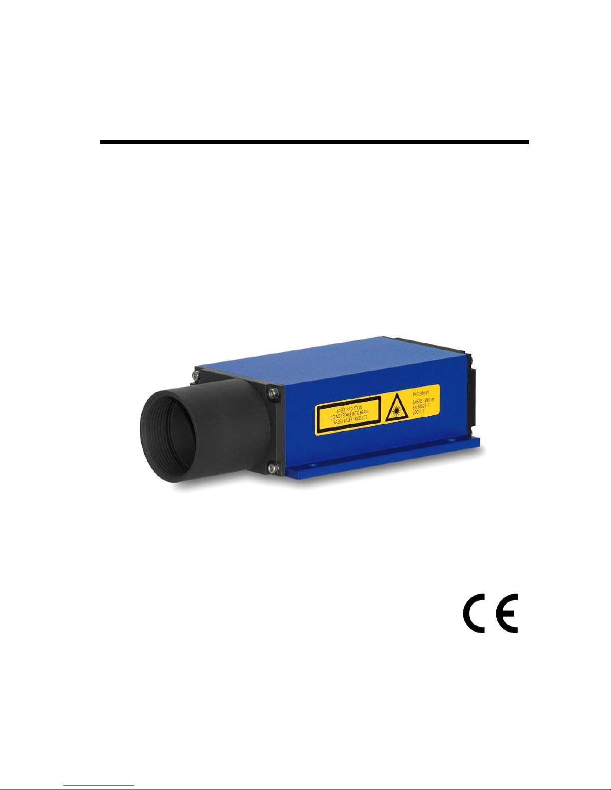
LDM41E and LDM42E Manual Content
ASTECH GmbH Page 3
I. Content
1 General.......................................................................................................6
2 Safety Instructions ..................................................................................... 8
2.1 General Safety Instructions...............................................................8
2.2 Intended & Conforming Use ............................................................. 8
2.3 Nonconforming use...........................................................................8
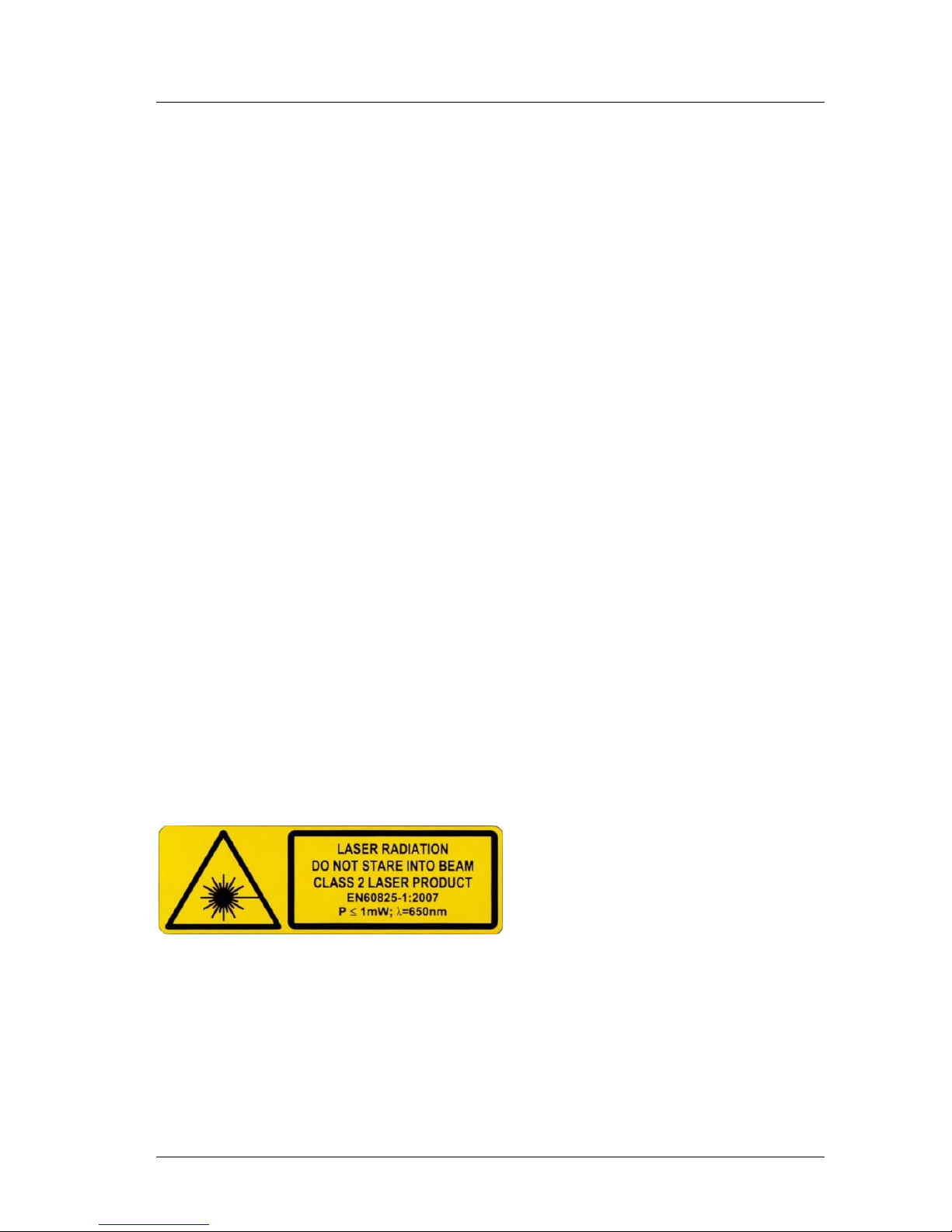
2.4 Laser Classification ............................................................................9
2.5 Electric Supply ................................................................................. 10
2.6 Important Operating Advice ........................................................... 10
3 Technical Data..........................................................................................11
4 Mechanical Mounting Conditions............................................................13
5 Electrical Connection ............................................................................... 15
5.1 Rear-Side Cover Terminals ..............................................................15
5.2 Assignment of Terminals.................................................................16
5.3 Shield and Grounding......................................................................18
6 Limiting Values for Voltages ....................................................................19
7 Start up ....................................................................................................20
7.1 Start up with RS232.........................................................................20
7.2 Start up with Ethernet.....................................................................21
8 Commands and Parameter ......................................................................23
8.1 General............................................................................................23
8.2 DT –distance tracking ..................................................................... 25
8.3 DS –distance tracking (<7 m).......................................................... 25
8.4 DW –distance tracking with target board (10 Hz) ..........................25
8.5 DX –distance tracking with target board (50 Hz) ........................... 26
8.6 DF –distance measurement with external trigger..........................26
8.7 DM –distance measurement .......................................................... 27
8.8 TP –internal temperature [°C] ........................................................ 27
8.9 SA –display/set average value [1..20] ............................................27
8.10 SD –display/set display format [d/h/s}] .........................................27
8.11 ST –display/set measure time [0..25].............................................28
8.12 SF –display/set scale factor ............................................................ 29