I. Table of contents
1Device description .......................................................................................................................................... 4
2Operating notes.............................................................................................................................................. 5
2.1 Installation ................................................................................................................................................ 5
2.2 Connections .............................................................................................................................................. 6
2.3 Signal-LED.................................................................................................................................................. 9
2.4 Maintenance and Cleaning ....................................................................................................................... 9
3Fieldbus interface (Option)........................................................................................................................... 10
4Parameterization .......................................................................................................................................... 11
4.1 Command input and VLMTool ................................................................................................................ 11
4.2 Parameter ............................................................................................................................................... 12
4.3 Additional commands ............................................................................................................................. 20
5Technical data............................................................................................................................................... 26
6Error messages ............................................................................................................................................. 27
7Dimensional and installation drawings......................................................................................................... 28
8Declaration of conformity ............................................................................................................................ 29
II. List of figures
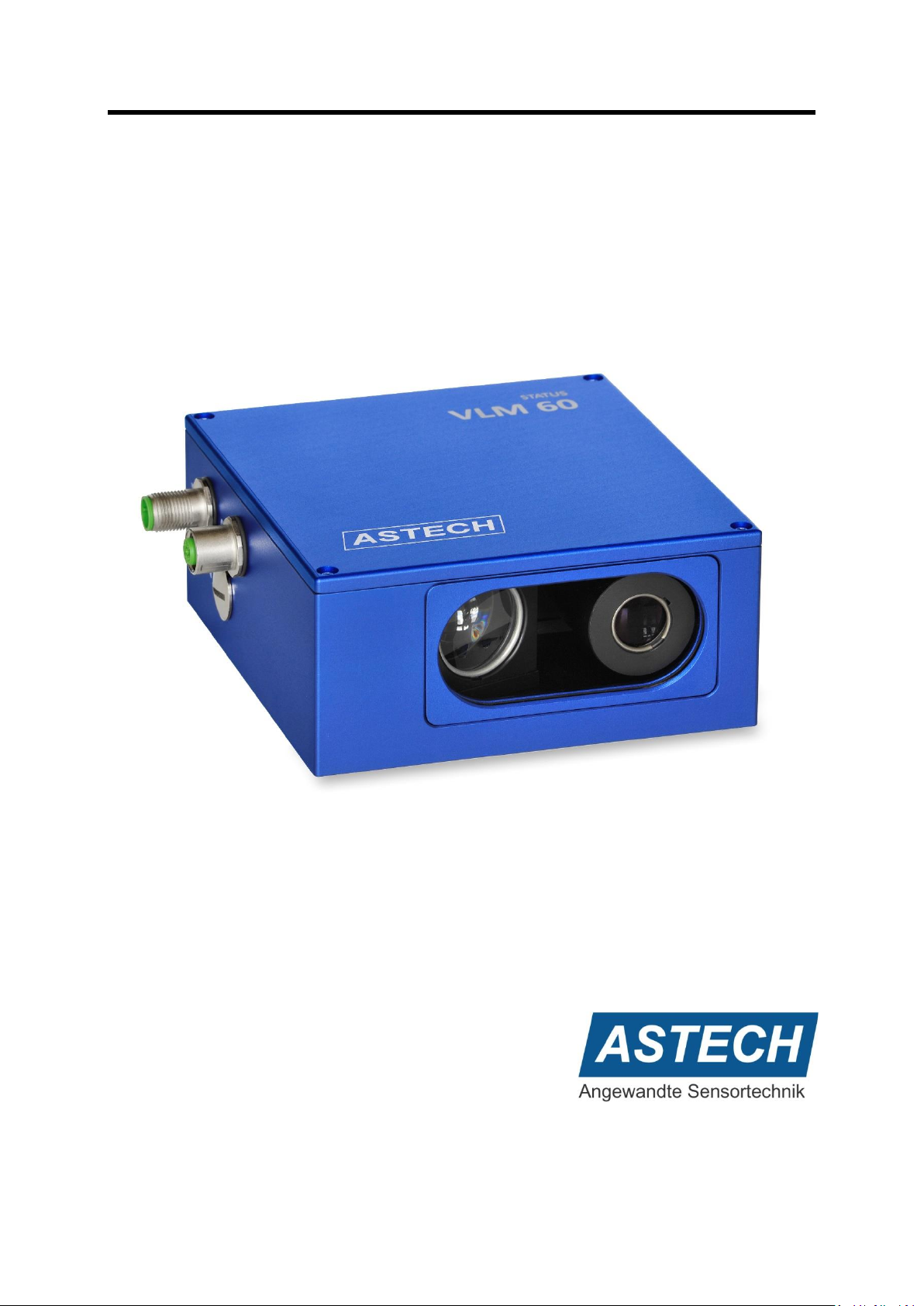
Figure 1: Structure of a VLM60 ............................................................................................................................... 4
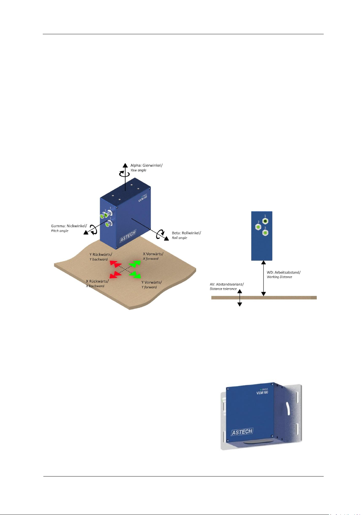
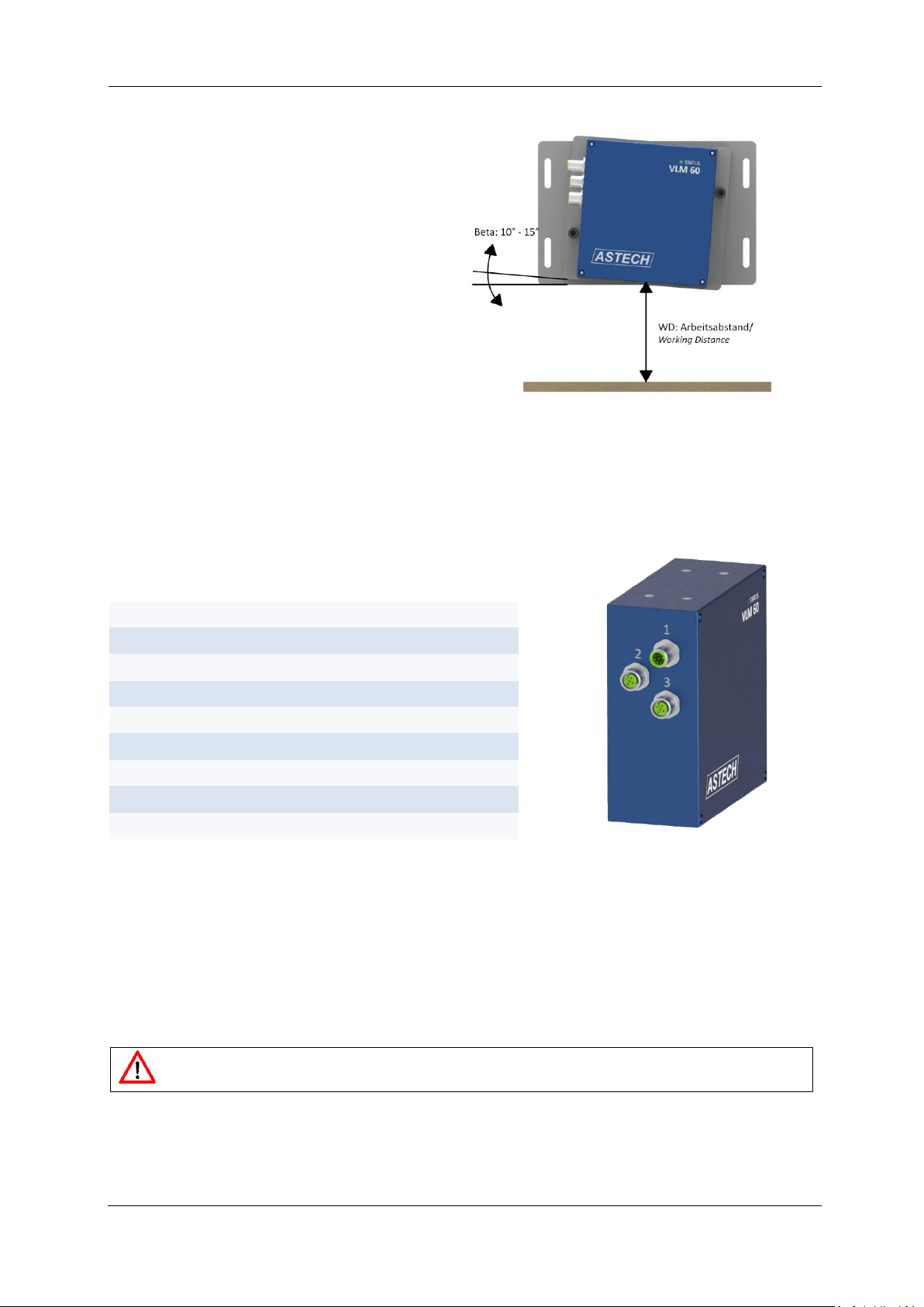
Figure 2: Mounting orientation of the VLM60 ........................................................................................................ 5
Figure 3: Working distance of the VLM60............................................................................................................... 5
Figure 4: VLM60 with mounting plate..................................................................................................................... 5
Figure 5: VLM60 with rotating plate ....................................................................................................................... 6
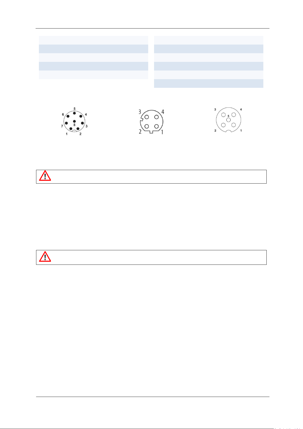
Figure 6: Connections.............................................................................................................................................. 6
Figure 7: Pin arrangement of the connections, seen from device side................................................................... 7
Figure 8: Pulse sequence of the encoder interface................................................................................................. 8
Figure 9: VLMTool ................................................................................................................................................. 11
Figure 10: Housing dimensions ............................................................................................................................. 28
Figure 11: Mounting dimensions .......................................................................................................................... 28
III. List of tables
Table 1: Configuration of connection 1................................................................................................................... 6
Table 2: Configuration of connection 2................................................................................................................... 7
Table 3: Configuration of connection 3................................................................................................................... 7
Table 4: Light conditions of the signal LED.............................................................................................................. 9