2. Factory settings.
3. Connecting CDS-5 IPmini radio module to power (3 options).
Option 1 - Directly from the included AC adapter PoE24V.
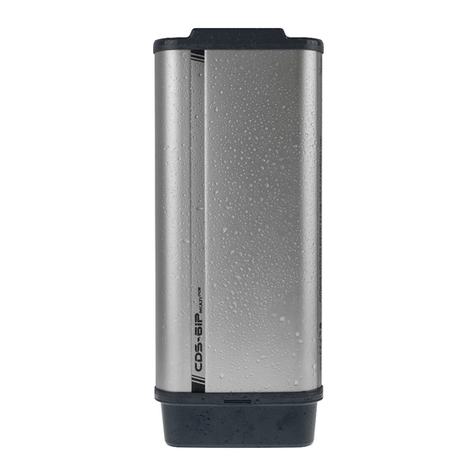
Insert the plug of the standard cable with the RJ45 termination into the
LAN connector in the CDS-5IP mini module. Connect the other termination
to the connector marked as “Data & Power Out” in the PoE unit delivered
together with whole set. Connect the computer / IP camera / recorder with
the network cable to the second connector in the power supply unit,
marked as “Data In.”
LAN/PoE
Power Socket
Reset Ground
Data In Data &
Power Out
ã áåá
Option 2 - Power for the camera and CDS-5IP mini with a single 12V
power supply through the included PoE splitter.
PoE splitter is used to power the CDS-5IPmini and cameras from a single
power supply 12-24V DC (or buffer power supply 13.8 V). With the
converter, there is no need for PoE power.
LAN/PoE
POE
12V DC
LAN
Reset Ground
ã áåá
Option 3 - power radio module (A) and the camera (C) with a Switch / AC PoE48V
via an additional converter PoER-24 (B) - (optional with an additional module
CAMSAT PoER-24)
4. Connecting to a computer.
Connect the radio module to the LAN adapter in the computer setting IP address
of the family 192.168.1.XX. (Eg. 192.168.1.99)
5. The necessary configuration settings - required:
a) Log on to the radio module CDS-5IPmini (default: 192.168.1.1, User Name: admin,
Password: password)
b) Set the destination IP address (SYSTEM/NETWORK SETTINGS)
c) In the receiver (the unit which will be connected to the DVR), set the AP
mode (Wireless / Basic Settings> Operation Mode:> AP). After that, click Apply.
d) Enter your own name of SSID links and then turn on the encryption of radio
transmission WPA2-PSK (SYSTEM / NETWORK SETTINGS> SSID> more ...>
Profile1> Network Authentication). In the WPA Passphrase, enter your own password.
To confirm changes, click Apply. Then reset the device by disconnecting for a moment
from power or through a tab: Management / Configuration File> Reboot the Device>
click Reboot. After restarting the device, disconnect the unit from the computer.
e) For transmitters (units that will be connected to the camera), set the mode to
Wireless Client(Wireless / Basic Settings> Operation Mode:> Wireless Client)
Confirm the change by Apply and reset the device. Then, in the same tab, click
Site Survey, select the network with the SSID the same as previously set in the
receiver, then press the Select AP confirm changes by Apply.
f) In the tab Wireless / Profile Settings select from the list the Network
Authentication> WPA2-ASK then in the WPA Passphrase, enter the password the
same as the receiver, confirm by pressing Apply.
g) Set the real distance between the transmitter and receiver in the transmitters.
In the receiver, set the distance of the furthest transmitter (WIRELESS/ADVANCED
SETTINGS)
g) Correctly connected transmitters should be visible in the list of linked devices
tab in STATUS/CONNECTIONS
1234
PoE A
B
C
QUICK START-UP
www.camsat.com
mini
Full instructions can be found at: www.camsat-cctv.com/cds-5ipmini Full instructions can be found at: www.camsat-cctv.com/cds-5ipmini
Note: The device manufacturer is not responsible for the devices that are not properly
protected and for related damage of the equipment and other network infrastructure.


