HYDACELECTRONIC HDA 4000 Series User manual

Mat
–Nr. 669704 / Stand: 27.01.2014 D/E
Druckmessumformer
HDA 4000
Mit Schiffs-Zulassungen
Pressure transmitter
HDA 4000
With Approvals for Shipping

D
Mat
–
Nr. 669704 / Stand: 27.01.2014 D/E
2
Inhalt
1 BESCHREIBUNG ...................................................................4
2 ALLGEMEINES ......................................................................5
3 MONTAGE..............................................................................5
4 ABMESSUNGEN....................................................................6
5 ANSCHLUSSBELEGUNGEN.................................................7
6 TECHNISCHE DATEN............................................................8
6.1 Druckmessumformer mit Keramikmesszellen.............................8
6.2 Druckmessumformer mit Edelstahlmesszellen...........................9
7 TYPENSCHLÜSSEL.............................................................10
7.1 Druckmessumformer mit Keramikmesszellen...........................10
7.2 Druckmessumformer mit Edelstahlmesszellen.........................11

D
Mat
–Nr. 669704 / Stand: 27.01.2014 D/E
3
Vorwort
Für Sie, den Benutzer unseres Produktes, haben wir in dieser
Dokumentation die wichtigsten Hinweise zum Bedienen und Warten
zusammengestellt.
Sie dient Ihnen dazu, das Produkt kennen zu lernen und seine
bestimmungsgemäßen Einsatzmöglichkeiten optimal zu nutzen.
Diese Dokumentation muss ständig am Einsatzort verfügbar sein.
Bitte beachten Sie, dass die in dieser Dokumentation gemachten
Angaben der Gerätetechnik zu dem Zeitpunkt der Literaturerstellung
entsprechen. Abweichungen bei technischen Angaben, Abbildungen
und Maßen sind deshalb möglich.
Entdecken Sie beim Lesen dieser Dokumentation Fehler oder haben
weitere Anregungen und Hinweise, so wenden Sie sich bitte an:
HYDAC ELECTRONIC GMBH
Technische Dokumentation
Hauptstraße 27
66128 Saarbrücken
-Deutschland-
Tel: +49(0)6897 / 509-01
Fax: +49(0)6897 / 509-1726
Die Redaktion freut sich über Ihre Mitarbeit.
„Aus der Praxis für die Praxis“

D
Mat
–Nr. 669704 / Stand: 27.01.2014 D/E
4
1 Beschreibung
Speziell für den Einsatz in der Schiffsbauindustrie wurden diese Druckmessumformer
auf Basis der Serie HDA 4000 entwickelt.
Zur Relativdruckmessung im Hochdruckbereich verfügt der HDA 4000 über eine
Edelstahl-Messzelle mit Dünnfilm-DMS, zur Relativ- oder Absolutdruckmessung im
Niederdruckbereich über eine Keramikmesszelle mit Dickschicht-DMS
Die Auswerteelektronik wandelt den gemessenen Druck in ein proportionales
Analogsignal von 4 .. 20 mA um.
Die Elektronikbaugruppe ist zum Schutz gegen Feuchtigkeit, Vibrationen und Schock
voll vergossen und in einem massiven Edelstahlgehäuse untergebracht.
Zur Verwendung der Druckmessumformer in der Schiffsindustrie sind diese bei den
unten aufgeführten Gesellschaften zugelassen:
American Bureau of Shipping ABS
Bureau Veritas BV
Det Norske Veritas DNV
German Lloyd GL
Lloyds Register of Shipping LRS

D
Mat
–Nr. 669704 / Stand: 27.01.2014 D/E
5
2 Allgemeines
Die Druckmessumformer der HDA 4000 Serien werden einzeln auf
computergesteuerten Prüfplätzen abgeglichen und anschließend einem Endtest
unterzogen. Sie sind wartungsfrei und arbeiten beim Einsatz innerhalb der
Spezifikationen (siehe Technische Daten) einwandfrei. Falls trotzdem Fehler auftreten
sollten, wenden Sie sich bitte an den HYDAC-Service. Fremdeingriffe in das Gerät
führen zum Erlöschen jeglicher Gewährleistungsansprüche. Falls Sie Fragen
bezüglich technischer Daten oder Eignung für Ihre Anwendungen haben, wenden Sie
sich bitte an den technischen Vertrieb.
3 Montage
Die Druckmessumformer können mit ihrem mechanischen Gewinde direkt in
hydraulische oder pneumatische Systeme eingebaut werden. In hydraulischen
Systemen ist die empfohlene Montageposition stehend, wobei der Druckanschluss
nach oben zeigen sollte. Auch in pneumatischen Systemen ist die empfohlene
Montageposition stehend, wobei jedoch der Druckanschluss nach unten zeigen sollte.
Bei Montage auf Navigationsbrücken ist eine Montage in direkter Nähe von
magnetischen Quellen zu unterlassen (vorgeschriebener Mindestabstand zwischen
Druckmessumformer und magnetischer Quelle: 1 m).
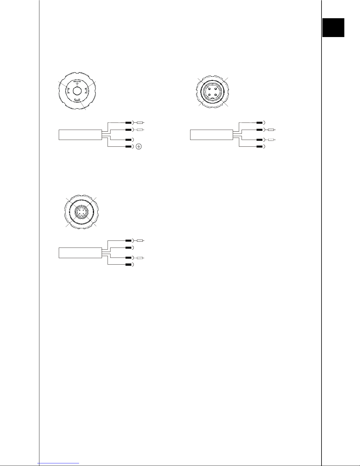
Anzugsdrehmoment zur Montage siehe Technische Daten. Der elektrische Anschluss
ist von einem Fachmann nach den jeweiligen Landesvorschriften durchzuführen (in
Deutschland: VDE 0100).
Alle HDA 4000 Druckmessumformer tragen das CE-Kennzeichen.
Konformitätserklärungen sind auf Anfrage erhältlich.
Es gelten die EMV-Normen: EN 61000-6-1/2/3/4. Die Forderungen der Normen
werden nur bei ordnungsgemäßer und fachmännischer Erdung des
Druckmessumformergehäuses erreicht. Beim Einschrauben in einen Hydraulikblock ist
es ausreichend, wenn der Block über das Hydrauliksystem geerdet ist. Bei einer
Schlauchmontage muss das Gehäuse separat geerdet werden.
Zusätzliche Montagehinweise, die erfahrungsgemäß den Einfluss elektromagnetischer
Störungen reduzieren:
•
Durchführung der elektrischen Installation von qualifiziertem Personal unter
Berücksichtigung der landesüblichen Vorschriften (oder entsprechend der
Bestimmungen der Zulassungsgesellschaften)
•
Verbindungskabel so kurz wie möglich halten
•
Verwendung von abgeschirmten Kabel
•
Vermeidung der direkten Nähe zu Verbindungskabeln von Geräten oder zu
elektrischen oder elektronischen Geräten, die Störungen erzeugen könnten sollte

D
Mat
–Nr. 669704 / Stand: 27.01.2014 D/E
6
4 Abmessungen

D
Mat
–Nr. 669704 / Stand: 27.01.2014 D/E
7
5 Anschlussbelegungen
Bemerkung:
Der Lastwiderstand RL ergibt sich aus dem intern im Auswertegerät befindlichen Messwiderstand und dem
Leitungswiderstand der Anschlussleitung.
HDA 4xx5-A
frei
RL
RL
Signal +
Signal -
Pin 1 Signal +
Pin 2 Signal -
Pin 3 frei
1
2
3
Stecker EN 175301-803 (DIN 43650) 3pol. + PE
HDA 4xx4-A
frei
RL
RL
Signal +
Signal -
Pin 1 frei
Pin 2 Signal +
Pin 3 Signal -
Pin 4 frei
1
2
3
Stecker Binder Serie 714 M18 4pol.
4
frei
HDA 4xx6-A
frei
RL
RL
Signal +
Signal -
Pin 1 Signal +
Pin 2 frei
Pin 3 Signal -
Pin 4 frei
1
2
3
Stecker M12x1 4pol.
frei
4
1
2
3
4
1
2
3
1
4
3
2
R
Lmax
= (U
B
-10V) / 20mA [kΩ]
R
Lmax
= (U
B
-10V) / 20mA [kΩ]
R
Lmax
= (U
B
-10V) / 20mA [kΩ]

D
Mat
–Nr. 669704 / Stand: 27.01.2014 D/E
8
6 Technische Daten
6.1 Druckmessumformer mit Keramikmesszellen
Eingangskenngrößen
HDA 4100
HDA 4300
Messbereiche [bar] 1 2,5 1 2,5 4 6 10 16 25 40
-1..1
-1..5 -1..9
Überlastbereiche [bar] 3 8 3 8 12 20 32 50 80 120
8 20 32
Berstdruck [bar] 5 12 5 12 18 30 48 75 120
180
12 30 48
Messbereiche [psi] 15 50 15 30 50 100 150 250 500
Überlastbereiche [psi] 45 174 45 116 174 290 460 725 1740
Berstdruck [psi] 70 260 70 174 260 430 690 1080
2600
Mechanischer Anschluss
(Anzugsdrehmoment)
G1/2 A DIN 3852, außen (45 Nm)
G1/4 A DIN 3852, außen (20 Nm)
9/16-18 UNF 2A, SAE 6, außen (20 Nm)
1/4-18 NPT, außen (40 Nm)
G1/2 A DIN 3852, außen (45 Nm)
G1/4 A DIN 3852, außen (20 Nm)
9/16-18 UNF 2A, SAE 6, außen (20 Nm)
1/4-18 NPT, außen (40 Nm)
Medienberührende Teile Anschlussstück: Keramik, Edelstahl
Dichtungen: FPM, EPDM
Anschlussstück: Keramik, Edelstahl
Dichtungen: FPM, EPDM
Ausgangsgrößen
Ausgangssignal, zulässige Bürde 4 ..20 mA, 2 Leiter
R
Lmax
.= (U
B
- 10 V) / 20 mA [kΩ]
4 ..20 mA, 2 Leiter
R
Lmax
.= (U
B
- 10 V) / 20 mA [kΩ]
Genauigkeit nach DIN 16086
(Grenzpunkteinstellung)
≤± 1 % FS max.
≤± 0,5 % FS typ.
≤± 1 % FS max.
≤± 0,5 % FS typ.
Genauigkeit bei Kleinstwert-
einstellung (B.F.S.L)
≤± 0,5 % FS max.
≤± 0,25 % FS typ.
≤± 0,5 % FS max.
≤± 0,25 % FS typ.
Temperaturkompensation ≤± 0,03 % FS / °C max ≤± 0,03 % FS / °C max
Nullpunkt ≤± 0,02 % FS / °C typ. ≤± 0,02 % FS / °C typ.
Temperaturkompensation ≤± 0,03 % FS / °C max ≤± 0,03 % FS / °C max
Spanne ≤± 0,02 % FS / °C typ. ≤± 0,02 % FS / °C typ.
Nicht-Linearität bei
Grenzpunkteinstellung nach
DIN 16086
≤± 0,5 % FS max.
≤± 0,25 % FS typ.
≤± 0,5 % FS max.
≤± 0,25 % FS typ.
Hysterese ≤± 0,4% FS max. ≤± 0,4 % FS max.
≤± 0,2 % FS typ. ≤± 0,2 % FS typ.
Wiederholbarkeit ≤± 0,1 % FS ≤± 0,1 % FS
Anstiegszeit ≤1 ms ≤1 ms
Langzeitdrift ≤± 0,3 % FS typ. / Jahr ≤± 0,3 % FS typ. / Jahr
Umgebungsbedingungen
Kompensierter Temperaturbereich -25 .. +85 °C -25 .. +85 °C
Betriebstemperaturbereich
1)
-30 .. +85 °C / -25 .. +85 °C -30 .. +85 °C / -25 .. +85 °C
Lagertemperaturbereich -30 .. +100 °C -30 .. +100 °C
Mediumstemperaturbereich
1)
-30 .. +85°C / -25 .. +85 °C -30 .. +100 °C / -25 .. +100 °C
- Zeichen EN 61000-6-1/1/2/3/4 EN 61000-6-1/1/2/3/4
Vibrationsbeständigkeit nach
DIN EN 60068-2-6 (10 .. 500 Hz)
≤20 g ≤20 g
Schutzart nach DIN 40050 IP 67 Stecker EN 175301-803 (DIN
43650)
M12x1 Stecker, bei Verwendung
einer IP 67 Kupplungsdose)
IP 67 Stecker EN 175301-
803 (DIN
43650)
M12x1 Stecker, bei Verwendung
einer IP 67 Kupplungsdose)
Sonstige Größen
Versorgungsspannung 10 .. 32 V 10 .. 32 V
Restwelligkeit der
Versorgungsspannung
≤5 % ≤5 %
Lebensdauer > 10 Millionen Lastwechsel
0 .. 100 % FS
> 10 Millionen Lastwechsel
0 .. 100 % FS
Gewicht ca. 150 g ca. 150 g
Anm.: Verpolungsschutz der Versorgungsspannung, Überspannungs-,
Übersteuerungsschutz, Lastkurzschlussfestigkeit sind vorhanden.
FS (Full Scale) = bezogen auf den vollen Messbereich
B.F.S.L. = Best Fit Straight Line
1)
-25°C mit FPM- oder EPDM-Dichtung, -30°C auf Anfrage

D
Mat
–Nr. 669704 / Stand: 27.01.2014 D/E
9
6.2 Druckmessumformer mit Edelstahlmesszellen
Eingangsgrößen
HDA 4400
HDA 4700
Messbereich [bar]
6 16 40 60 100 250 400 600 6 16 40 60 100 250 400 600
Überlastbereiche [bar]
15 32 80 120 200 500 800 1000
15 32 80 120 200 500 800 1000
Berstdruck [bar]
100 200 200 300 500 1000
2000
2000
100 200 200 300 500 1000
2000
2000
Messbereich / [psi]
150 500 750 1000 1500
150
500
750
1000
1500
3000
5000
6000
9000
3000
5000
6000
9000
Überlastbereiche [psi]
290
1160
1740
2900
2900
290
1160
1740
2900
2900
7250
11600
11600
1
4500
7250
11600
11600
14500
Berstdruck [psi]
1450
2900
4350
7250
7250
1450
2900
4350
7250
7250
14500
29000
29000
29000
14500
29000
29000
29000
Mechanischer Anschluss
(Anzugsdrehmoment)
G1/2 A DIN 3852, außen (45 Nm)
G1/4 A DIN 3852, außen (20 Nm)
9/16-18 UNF 2A, SAE 6, außen (20 Nm)
1/4-18 NPT, außen (40 Nm)
G1/2 A DIN 3852, außen (45 Nm)
G1/4 A DIN 3852, außen (20 Nm)
9/16-18 UNF 2A, SAE 6, außen (20 Nm)
1/4-18 NPT, außen (40 Nm)
Medienberührende Teile Anschlussstück: Edelstahl
Dichtung: FPM
Anschlussstück: Edelstahl
Dichtung: FPM
Ausgangsgrößen
Ausgangssignal, zulässige Bürde 4 ..20 mA, 2 Leiter
R
Lmax
.= (U
B
- 10 V) / 20 mA [kΩ]
4 ..20 mA, 2 Leiter
R
Lmax
.= (U
B
- 10 V) / 20 mA [kΩ]
Genauigkeit nach DIN 16086
(Grenzpunkteinstellung)
≤± 1 % FS max.
≤± 0,5 % FS typ.
≤± 0,5 % FS max.
≤± 0,25 % FS typ.
Genauigkeit bei Kleinstwert-
einstellung (B.F.S.L)
≤± 0,5 % FS max.
≤± 0,25 % FS typ.
≤± 0,25 % FS max.
≤± 0,15 % FS typ.
Temperaturkompensation ≤± 0,025 % FS / °C max ≤± 0,015 % FS / °C max.
Nullpunkt ≤± 0,015 % FS / °C typ. ≤± 0,008 % FS / °C typ.
Temperaturkompensation ≤± 0,025 % FS / °C max ≤± 0,015 % FS / °C max.
Spanne ≤± 0,015 % FS / °C typ. ≤± 0,008 % FS / °C typ.
Nicht-Linearität bei
Grenzpunkteinstellung nach
DIN 16086
≤± 0,3 % FS max.
≤± 0,15 % FS typ.
≤± 0,3 % FS max.
≤± 0,15 % FS typ.
Hysterese ≤± 0,4 % FS max. ≤± 0,1 % FS max.
≤± 0,2 % FS typ. ≤± 0,05 % FS typ.
Wiederholbarkeit ≤± 0,1 % FS ≤± 0,05 % FS
Anstiegszeit ≤1 ms ≤1 ms
Langzeitdrift ≤± 0,3 % FS typ. / Jahr ≤± 0,1 % FS typ. / Jahr
Umgebungsbedingungen
Kompensierter Temperaturbereich -25 .. +85 °C -25 .. +85 °C
Betriebstemperaturbereich
2)
-40 .. +85 °C / -25 .. +85 °C -40 .. +85 °C / -25 .. +85 °C
Lagertemperaturbereich -40 .. +100 °C -40 .. +100 °C
Mediumstemperaturbereich
2)
-40 .. +100 °C / -25 .. +100 °C -40 .. +100 °C / -25 .. +100 °C
- Zeichen EN 61000-6-1/1/2/3/4 EN 61000-6-1/1/2/3/4
Vibrationsbeständigkeit nach
DIN EN 60068-2-6 (10 .. 500 Hz)
≤20 g ≤20 g
Schutzart nach DIN 40050 IP 67 Stecker EN 175301-803
(DIN 43650)
M12x1 Stecker, bei Verwendung
einer IP 67 Kupplungsdose)
IP 67 Stecker EN 175301-803
(DIN 43650)
M12x1 Stecker, bei Verwendung
einer IP 67 Kupplungsdose)
Sonstige Größen
Versorgungsspannung 2-Leiter 10 .. 32 V 10 .. 32 V
Restwelligkeit der
Versorgungsspannung
≤5 % ≤5 %
Lebensdauer 10 Millionen Lastwechsel
0 .. 100 % FS
10 Millionen Lastwechsel
0 .. 100 % FS
Gewicht ca. 150 g ca. 150 g
Anm.: Verpolungsschutz der Versorgungsspannung, Überspannungs-,
Übersteuerungsschutz, Lastkurzschlussfestigkeit sind vorhanden.
FS (Full Scale) = bezogen auf den vollen Messbereich
B.F.S.L. = Best Fit Straight Line
2)
-25°C mit FPM- oder EPDM-Dichtung, -40°C auf Anfrage

D
Mat
–Nr. 669704 / Stand: 27.01.2014 D/E
10
7 Typenschlüssel
7.1 Druckmessumformer mit Keramikmesszellen
HDA 4 X X X - A - XXXXX - SXX - X 1
Genauigkeitsklasse
1 = 1 % FS max., absolut
3 = 1 % FS max., relativ
Anschlussart, mechanisch
2 = G1/2 A DIN 3852 (außen)
4 = G1/4 A DIN 3852 (außen)
7 = 9/16-18 UNF 2A, SAE 6 (außen)
8 = 1/4-18 NPT (außen)
Anschlussart, elektrisch
4 = Gerätestecker Binder Serie 714 M18, 4 pol.
(ohne Kupplungsdose)
5 = Gerätestecker EN 175301-803 (DIN 43650), 3 pol. + PE
(inklusive Kupplungsdose)
6 = Gerätestecker M12 x 1, 4 pol.
(ohne Kupplungsdose)
Signal
A = 4 .. 20 mA, 2-Leiter
Druckbereiche
Genauigkeitsklasse „1“
4-stellig für bar: 01,0; 02,5
5-stellig für psi: 00015; 00050
Genauigkeitsklasse „3“
4-stellig für bar: 01,0; 02,5; 04,0; 06,0; 0010; 0016; 0025; 0040
00001 (-1 .. +1); 00005 (-1 .. +5); 00009 (-1 .. +9)
5-stellig für psi: 00015; 00030; 00050; 00100; 00150; 00250; 00500
Modifikationsnummer
SXX = mit Schiffs-Zulassungen
Dichtungsmaterial (medienberührend)
F = FPM Dichtung (z.B. für Hydrauliköle)
E = EPDM Dichtung (z.B. für Kältemittel)
Anschlussmaterial (medienberührend)
1 = Edelstahl

D
Mat
–Nr. 669704 / Stand: 27.01.2014 D/E
11
7.2 Druckmessumformer mit Edelstahlmesszellen
HDA 4 X X X - A - XXXXX - SXX
Genauigkeitsklasse
4 = 1 % FS max.
7 = 0,5 % FS max.
Anschlussart, mechanisch
2 = G1/2 A DIN 3852 (außen)
4 = G1/4 A DIN 3852 (außen)
7 = 9/16-18 UNF 2A, SAE 6 (außen)
8 = 1/4-18 NPT (außen)
Anschlussart, elektrisch
4 = Gerätestecker Binder Serie 714 M18, 4 pol.
(ohne Kupplungsdose)
5 = Gerätestecker EN 175301-803 (DIN 43650), 3 pol. + PE
(inklusive Kupplungsdose)
6 = Gerätestecker M12 x 1, 4 pol.
(ohne Kupplungsdose)
Signal
A = 4 .. 20 mA, 2-Leiter
Druckbereiche
4-stellig für bar: 0006; 0016; 0040; 0060; 0100; 0250; 0400; 0600
5-stellig für psi: 00150;00500; 00750; 01000; 01500; 03000; 05000; 06000; 09000
Modifikationsnummer
SXX = mit Schiffs-Zulassungen

D
Mat
–Nr. 669704 / Stand: 27.01.2014 D/E
12
HYDAC ELECTRONIC GMBH
Hauptstr. 27
D-66128 Saarbrücken
Germany
Web: www.hydac.com
E-Mail:[email protected]
Tel.: +49 (0)6897 509-01
Fax.: +49 (0)6897 509-1726
HYDAC Service
Für Fragen zu Reparaturen steht Ihnen der HYDAC Service zur Verfügung.
HYDAC SERVICE GMBH
Hauptstr. 27
D-66128 Saarbrücken
Germany
Tel.: +49 (0)6897 509-1936
Fax.: +49 (0)6897 509-1933
Anmerkung
Die Angaben in dieser Bedienungsanleitung beziehen sich auf die beschriebenen
Betriebsbedingungen und Einsatzfälle. Bei abweichenden Einsatzfällen und/oder
Betriebsbedingungen wenden Sie sich bitte an die entsprechende Fachabteilung.
Bei technischen Fragen, Hinweisen oder Störungen nehmen Sie bitte Kontakt mit Ihrer
HYDAC-Vertretung auf.
Technische Änderungen sind vorbehalten.

Mat
–Nr. 669704 / Stand: 27.01.2014 D/E
Druckmessumformer
HDA 4000
Mit Schiffs-Zulassungen
Pressure transmitter
HDA 4000
With Ship-Approvals

E
Mat
–
Nr. 669704 / Stand: 27.01.2014 D/E
2
Content
1
FUNCTIONAL DESCRIPTION.....................................................................4
2
GENERAL REMARKS.................................................................................5
3
ASSEMBLY..................................................................................................5
4
DIMENSIONS...............................................................................................6
5
PIN CONNECTION ......................................................................................7
6
TECHNICAL SPECIFICATIONS..................................................................8
6.1
Pressure transmitters with Ceramic cell..................................................8
6.2
Pressure transmitters with stainless steel cell .......................................9
7
MODEL CODE ..........................................................................................10
7.1
Pressure transmitter with ceramic cell ..................................................10
7.2
Pressure transmitters with stainless steel cell .....................................11

E
Mat
–Nr. 669704 / Stand: 27.01.2014 D/E
3
Preface
We have compiled the most important instructions for the operation
and maintenance of our product for you, its user, in this
documentation.
It will acquaint you with the product and assist you in using it as
intended in an optimal manner.
Keep it in the vicinity of the product so it is always available.
Note that the information on the unit's engineering contained in the
documentation was that available at the time of publication. There may
be deviations in technical details, figures, and dimensions as a result.
If you discover errors while reading the documentation or have
additional suggestions or notes, contact us at:
HYDAC ELECTRONIC GMBH
Technical Documentation
Hauptstraße 27
66128 Saarbrücken
-Germany-
Tel: +49(0)6897 / 509-01
Fax: +49(0)6897 / 509-1726
The editorial board would welcome your contributions.
„Putting experience into practice“

E
Mat
–Nr. 669704 / Stand: 27.01.2014 D/E
4
1 Functional Description
Preferably for applications in marine business / ship industry these pressure
transmitters were designed based on standard HDA 4000 series.
Featuring ceramic sensor cells, absolute and relative pressure in low pressure
applications are measured. For measurements in high pressure applications stainless
steel sensor cells are used.
The electronic circuits with HYDAC-ASIC proportionally change pressure readings into
a 4..20 mA analogue signal. To protect against moisture, vibration, and shock the
electronics are fully encapsulated and put in a solid stainless steel housing.
For the use in ship industry the following companies have approved the HDA 4000:
American Bureau of Shipping ABS
Bureau Veritas BV
Det Norske Veritas DNV
German Lloyd GL
Lloyds Register of Shipping LRS

E
Mat
–Nr. 669704 / Stand: 27.01.2014 D/E
5
2 General Remarks
Every pressure transmitter HDA 4000 series is calibrated on computer-controlled test
rigs and submitted to a final test.
The pressure transmitters do not require any maintenance and operate satisfactorily
when used according to their specifications (see technical details). In the case of any
unsatisfactorily operation, please contact HYDAC Service.
Interference from anyone other than HYDAC personnel will invalidate all warranty
claims. If there are any queries regarding technical details or suitability of the pressure
transmitter for any particular application please contact HYDAC Product Management.
3 Assembly
The pressure transmitters are ready for mounting directly to the hydraulic system by
means of their thread connection. The recommended mounting position is in hydraulic
applications vertical with the pressure connection pointing upwards and in pneumatic
applications vertical with the pressure connection pointing downwards. For mounting
on navigation bridges the place of mounting has to be outside of the vicinity of magnetic
compasses (minimum distance 1 m). Mounting torque see Technical Data. The
electrical connection should be carried out by a qualified electrician according to the
relevant regulations of the country concerned.
All pressure transmitter HDA 4000 series carry the mark. A declaration of
conformity is available on request.
The relevant EMC standards apply: EN 61000-6-1/2/3/4.
The requirements of the standards are fulfilled only if the pressure transmitter
housings are earthed correctly by qualified personnel. When fitting the pressure
transmitters into manifold blocks it is sufficient if the block itself is earthed through the
hydraulic system. In the case of hose-mounting the housing must be earthed
separately.
In the following please find additional assembly notes that, by experience, reduce the
effect of electromagnetic interference:
•The electrical connections should be carried out by a qualified electrician according
to the relevant regulations of the country concerned (resp. the requirements of
individual Approval Company).
•Keep connection wiring as short as possible.
•Use screened cables.
•Avoid direct proximity to connecting lines of user units or electrical or electronic
units that may cause interference.

E
Mat
–Nr. 669704 / Stand: 27.01.2014 D/E
6
4 Dimensions

E
Mat
–Nr. 669704 / Stand: 27.01.2014 D/E
7
5 Pin connection
Note:
The load resistance R
L
is the sum of the measuring resistance inside the evaluation unit and the line resistance of
the connection line.
HDA 4xx5-A
n.c.
RL
RL
Signal +
Signal -
Pin 1 Signal +
Pin 2 Signal -
Pin 3 n.c.
1
2
3
Plug
EN 175301-803 (DIN 43650)
3-pole + PE
HDA 4xx4-A
n.c.
RL
RL
Signal +
Signal -
Pin 1 n.c.
Pin 2 Signal +
Pin 3 Signal -
Pin 4 n.c.
1
2
3
Plug Binder series 714 M18 4-pole
4
n.c.
HDA 4xx6-A
n.c.
RL
RL
Signal +
Signal -
Pin 1 Signal +
Pin 2 n.c.
Pin 3 Signal -
Pin 4 n.c.
1
2
3
Plug M12x1 4-pole
n.c.
4
1
2
3
4
1
2
3
1
4
3
2
R
Lmax
= (U
B
-10V) / 20mA [kΩ]
R
Lmax
= (U
B
-10V) / 20mA [kΩ]
R
Lmax
= (U
B
-10V) / 20mA [kΩ]

E
Mat
–Nr. 669704 / Stand: 27.01.2014 D/E
8
6 Technical specifications
6.1 Pressure transmitters with Ceramic cell
Input data
HDA 4100
HDA 4300
Measuring ranges [bar] 1 2,5 1 2,5 4 6 10 16 25 40
-1..1 -1..5 -1..9
Overload pressures [bar] 3 8 3 8 12 20 32 50 80 120
8 20 32
Burst pressures [bar] 5 12 5 12 18 30 48 75 120
180
12 30 48
Measuring ranges [psi] 15 50 15 30 50 100 150 250 500
Overload pressures [psi] 45 174 45 116 174 290 460 725 1740
Burst pressures [psi] 70 260 70 174 260 430 690 1080
2600
Mechanical connection
(Tightening torque)
G1/2 A DIN 3852, male (45 Nm)
G1/4 A DIN 3852, male (20 Nm)
9/16-18 UNF 2A, SAE 6, male (20 Nm)
1/4-18 NPT, male (40 Nm)
G1/2 A DIN 3852, male (45 Nm)
G1/4 A DIN 3852, male (20 Nm)
9/16-18 UNF 2A, SAE 6, male (20 Nm)
1/4-18 NPT, male (40 Nm)
Parts in contact with medium Mech. connect.: Ceramic, Stainless steel
Seal: FPM, EPDM
Mech. connect.: Ceramic, Stainless steel
Seal: FPM, EPDM
Output data
Output signal, permitted resistance 4 ..20 mA, 2 conductor
R
Lmax
.= (U
B
- 10 V) / 20 mA [kΩ]
4 ..20 mA, 2 conductor
R
Lmax
.= (U
B
- 10 V) / 20 mA [kΩ]
Accuracy to DIN 16086
(Max. setting)
≤± 1 % FS max.
≤± 0.5 % FS typ.
≤± 1 % FS max.
≤± 0.5 % FS typ.
Accuracy at. Min. setting
(B.F.S.L)
≤± 0.5 % FS max.
≤± 0.25 % FS typ.
≤± 0.5 % FS max.
≤± 0.25 % FS typ.
Temperature compensation ≤± 0.03 % FS / °C max ≤± 0.03 % FS / °C max
Zero point ≤± 0.02 % FS / °C typ. ≤± 0.02 % FS / °C typ.
Temperature compensation ≤± 0.03 % FS / °C max ≤± 0.03 % FS / °C max
Over range ≤± 0.02 % FS / °C typ. ≤± 0.02 % FS / °C typ.
Non-linearity at Max. setting
to DIN 16086
≤± 0.5 % FS max.
≤± 0.25 % FS typ.
≤± 0.5 % FS max.
≤± 0.25 % FS typ.
Hysteresis ≤± 0.4 % FS max. ≤± 0.4 % FS max.
≤± 0.2 % FS typ. ≤± 0.2 % FS typ.
Repeatability ≤± 0.1 % FS ≤± 0.1 % FS
Rise time ≤1 ms ≤1 ms
Long-term drift ≤± 0.3 % FS typ. / year ≤± 0.3 % FS typ. / year
Ambient conditions
Compensated temperature range -25 .. +85 °C -25 .. +85 °C
Operating temperature range
1)
-30 .. +85 °C / -25 .. +85 °C -30 .. +85 °C / -25 .. +85 °C
Storage temperature range -30 .. +100 °C -30 .. +100 °C
Fluid temperature range
1)
-30 .. +85C / -25 .. +85 °C -30 .. +100 °C / -25 .. +100 °C
- Zeichen EN 61000-6-1/1/2/3/4 EN 61000-6-1/1/2/3/4
Vibration resistance to
DIN EN 60068-2-6 (10 .. 500 Hz)
≤20 g ≤20 g
Protection class to DIN 40050 IP 67 Connector EN 175301-803
(DIN 43650)
M12x1 when an IP 67 connector
is used
IP 67 Connector to EN 175301-803
(DIN 43650)
M12x1 when an IP 67 connector
is used
Other data
Supply voltage 10 .. 32 V 10 .. 32 V
Residual ripple of supply voltage ≤5 % ≤5 %
Life expectancy > 10 million cycles
0 .. 100 % FS
> 10 million cycles
0 .. 100 % FS
Weight approx. 150 g approx. 150 g
Note.: Reverse polarity protection of the supply voltage, excess voltage, override,
short circuit protection are provided.
FS (Full Scale) = relative to the complete measuring range
B.F.S.L. = Best Fit Straight Line
1)
-25°C with FPM or EPDM seal, -30 °C on request
Other manuals for HDA 4000 Series
1
This manual suits for next models
4
Table of contents
Languages:
Other HYDACELECTRONIC Transmitter manuals

HYDACELECTRONIC
HYDACELECTRONIC HFT 250 User manual

HYDACELECTRONIC
HYDACELECTRONIC ETS 4000 Series User manual

HYDACELECTRONIC
HYDACELECTRONIC HPT 500 Series User manual

HYDACELECTRONIC
HYDACELECTRONIC HLT 2100-R1 User manual

HYDACELECTRONIC
HYDACELECTRONIC HLT 2550-L2 User manual

HYDACELECTRONIC
HYDACELECTRONIC HDA 4700 User manual

HYDACELECTRONIC
HYDACELECTRONIC HFT 2100 User manual

HYDACELECTRONIC
HYDACELECTRONIC HLT 2100 Series User manual

HYDACELECTRONIC
HYDACELECTRONIC HDA 4144 User manual

HYDACELECTRONIC
HYDACELECTRONIC HDA 7400 User manual