manuals.online logo
Brands
  1. Home
  2. •
  3. Brands
  4. •
  5. Astra
  6. •
  7. Lifting System
  8. •
  9. Astra HD8Ec User manual

Astra HD8Ec User manual

Other Astra Lifting System manuals

Astra powerLIFT AE5000 User manual

Astra

Astra powerLIFT AE5000 User manual

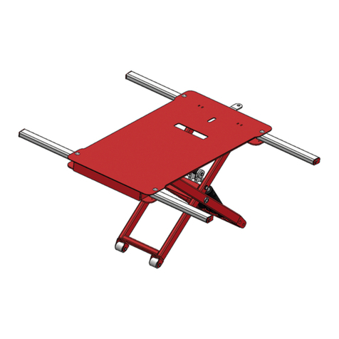
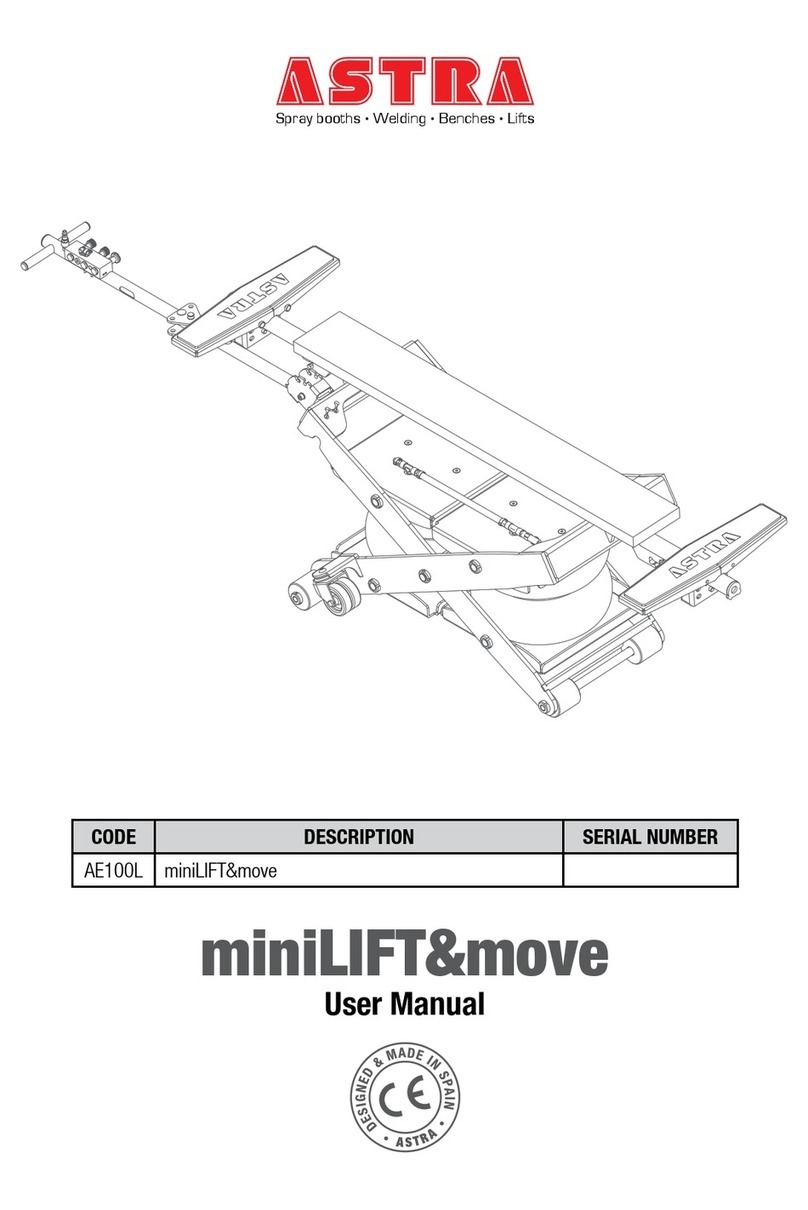
Astra miniLIFT&move User manual

Astra

Astra miniLIFT&move User manual

Popular Lifting System manuals by other brands

probst SDH-H-15 operating instructions

probst

probst SDH-H-15 operating instructions

Bruno OUTDOOR ELITE CRE-2110E Operator's manual

Bruno

Bruno OUTDOOR ELITE CRE-2110E Operator's manual

matev FPS Mounting Assembly Installation Guide

matev

matev FPS Mounting Assembly Installation Guide

Vestil CYL-HLT Series instruction manual

Vestil

Vestil CYL-HLT Series instruction manual

Butts Tools BXS0002 operating instructions

Butts Tools

Butts Tools BXS0002 operating instructions

Safelift MoveAround MA60 Original instructions

Safelift

Safelift MoveAround MA60 Original instructions

Terex Genie Z452513A-48153 Service and repair manual

Terex

Terex Genie Z452513A-48153 Service and repair manual

Granberg InDIago 510 Operating and care instructions

Granberg

Granberg InDIago 510 Operating and care instructions

EUFAB Bike Lift operating instructions

EUFAB

EUFAB Bike Lift operating instructions

morse 82H-124 Operator's manual

morse

morse 82H-124 Operator's manual

Braun NL955 Series Operator's manual

Braun

Braun NL955 Series Operator's manual

Protekt AT 252 instruction manual

Protekt

Protekt AT 252 instruction manual

R. Beck Maschinenbau HS 600 operating manual

R. Beck Maschinenbau

R. Beck Maschinenbau HS 600 operating manual

Nova Technology International, LLC NAS Series quick start guide

Nova Technology International, LLC

Nova Technology International, LLC NAS Series quick start guide

Genie Z-60/34 Operator's manual

Genie

Genie Z-60/34 Operator's manual

Screen Technics INTERFIT Vertical Up Lift instructions

Screen Technics

Screen Technics INTERFIT Vertical Up Lift instructions

Drive DUPONT SAMERY Hermes user manual

Drive

Drive DUPONT SAMERY Hermes user manual

Custom Equipment Hy-Brid 3 Series MAINTENANCE & TROUBLESHOOTING MANUAL

Custom Equipment

Custom Equipment Hy-Brid 3 Series MAINTENANCE & TROUBLESHOOTING MANUAL

manuals.online logo
manuals.online logoBrands
  • About & Mission
  • Contact us
  • Privacy Policy
  • Terms and Conditions

Copyright 2025 Manuals.Online. All Rights Reserved.

INTRODUCTION 3
ASTRA HD8Ec SECTION I
PREFACE
Definitions adopted in the current Manual
The Company ASTRA VEICOLI INDUSTRIALI, Via Caorsana, 79 - 29100 PIACENZA (Italy) is hereinafter called Manufacturer.
The current WORKSHOP MANUAL is hereinafter called Manual.
The equipment dealt with in the current Manual is hereinafter called vehicle.
The operator directly or indirectly involved in vehicle repair is hereinafter called operator.
Introduction
The current Manual applies essentially to authorised workshop technical staff.
This Manual provides technical information but cannot replace a thorough professional experience.
This Manual contains all data and information required to perform correct checking and setting up operations as well as repair
and overhaul operations.
Read this Manual right through before performing any operation on the vehicle.
Compliance with the provided information and the use of the recommended tools guarantee correct repair and avoid damages
to operators.
You will frequently see that parts of the text are highlighted as shown below:
Failure to heed and/or correctly carry out procedures, technical information and precautions given may cause injury.
Failure to heed and/or correctly carry out procedures, technical information and precautions given may cause damage
to the vehicle.
Procedures, technical information and precautions which must be highlighted.
Failure to heed and/or correctly carry out procedures, technical information and precautions given may cause environ-
mental damages.
This Manual has been divided into Sections, each of which has a number and its relevant contents are indicated in the Index of
Sections.
Each section features a main Unit (e.g.: engine, gears, etc.)
Where possible, the same sequence of procedures has been followed for easy reference.
Diagram and symbols have been widely used to give a clearer and more immediate illustration of the subject being dealt with (see
next page) instead of giving descriptions of some operations or procedures.
α
Example:
Tighten to torque
Tighten to torque + angular value
Ø 1 = Housing for connecting rod small end bush
Ø 2 = Housing for connecting rod bearings
INTRODUCTION 5
ASTRA HD8Ec SECTION I
MEASURES (INTERNATIONAL SYSTEM)
Force in N (Newton)
Conversion:
I N = 0,1019 kg
1 kg = 9,81 N
Power in kW (kilowatt)
Other units in use:
HP (Horsepower)
Conversion:
1 kW = 1,36 CV
1 kW = 1,34 HP
1 CV = 0,736 kW
1 CV = 0,986 HP
1 HP = 0,746 kW
1 HP = 1,014 CV
Torque in Nm (Newton/metre)
Conversion:
1 Nm = 0,1019 kgm
1 kgm= 9,81 Nm
1 kgm= 10 Nm *
Specific consumption in g/kWh (grams per kilo-
watthour)
Other unit in use:
g/CVh (grams per horsepower-hour)
Conversion:
I g/kWh = 0,736 g/CVh
1g/CVh = 1,36g/kWh
Pressure in kPa (kilopascal)
Other units in use:
kg/cm2(kilograms per square centimeter)
Atm (metric atmosphere)
psi (pounds per square inch)
Conversion:
I kg/cm2=1Atm
I kg/cm2= 98,1 kPa
I kg/cm2= 0,981 bar
I kg/cm2=1bar*
I kg/cm2= 14,22 psi
I bar = 100 kPa
I bar = 1,02 kg/cm2
I bar = 14,51 psi
Ipsi = 6,9kPa
I psi = 0,069 bar
I psi = 0,0703 kg/cm2
I kPa = 0,145 psi
I kPa = 0,0102 kg/cm2
IkPa = 0,01bar
Conversion values for British units
0,1 mm = 3,937 mils
I mm = 0,039 inch
I m = 3,281 ft.
I km = 0,621 miles
Icm
3=0,06Icu.in.
I l = I ,759 pts (0,88 imp.qts)
I bar = 14,5038 psi
I g = 0,035 oz. (0,564 dr.)
I kg = 2,205 Ibs.
(in case of differences in temperature 1 °C = 1.8 °F)
(*) Nm and bar are converted according to the ratios 10:1
and 1:1.
60593
FRONT SIDE
stage 4:
angle, inner
screws
55º
60592
60594
60593
stage 1:
pretightening,
outer screws
30 Nm
FRONT SIDE
FRONT SIDE
stage 2:
pretightenig,
inner screws
120 Nm
stage 5:
angle, outer
screws
60º
60593
FRONT SIDE
stage 3:
angle, inner
screws
60º
FRONT SIDE
Figure 8
ENGINE - F3B 43
ASTRA HD8Ec SECTION 3
TIGHTENING ORDER OF GEARBOX TO ENGINE BLOCK FASTENING SCREWS
1. Fuel valve
2. Pumping element
3. Fuel discharge
4. Filling and flowing back channel
1. Fuel valve
2. Pumping element
3. Fuel discharge
4. Filling and flowing back channel
60669
Figure 227
Filling phase
During the filling phase, the pumping element (2) moves to
its upper position.
The highest cam position is passed and the rocker roller gets
closer to the cam basic circle.
The fuel valve (1) is open and the fuel can flow into the
injector from the lower channel (4) of the cylinder head.
The filling phase continues until the pumping element has
reached its upper end-of-stroke position.
60670
Figure 228
Injection phase
The injection phase starts when, during the pumping element
descending phase, the solenoid valve is energized and the fuel
valve (1) closes. Delivery start time, properly processed by
the electronic control unit, depends on engine operating
conditions. Through the rocker, the cam continues to
activate the pumping element (2) and the injection phase
continues as long as the fuel valve is closed (1).
ENGINE - F3B 133
ASTRA HD8Ec SECTION 3
Injection phases
MANUAL GEARBOX 3
ASTRA HD8Ec SECTION 6
DESCRIPTION
The ZF 16S 1620 and ZF 16S 2320 TD version consist of:
-a central box containing the primary shaft, drive input shaft,
secondary shaft and the cogs of the four forward and one
reverse gear;
-a rear casing containing the Epicyclical Reducer Group
(G.R.E). The function of this is to double the number of
forward gears by means of epicyclical gears with helical
teeth.
This gives a range of gears that starting with four input
ratios permits eight different output ratios (four normal
ratio and four low ratio gears);
-a front casing containing the “splitter”, that gives a further
double selection for each of the eight forward gears and
for the reverse gear.
The “splitter” halves the difference between two
successive gears, effectively splitting each gear into a slow
ratio (L = slow ratio) and a fast ratio (S = fast ratio).
These gearboxes therefore have a total of sixteen forward
gears with finely scaled ratios, all engageable in succession, and
two reverse gears.
Thesynchronisersaresingleconetype.
Lubrication is by means of a gear pump.
The double H type gear shift control is equipped with a
pneumatically powered “servoshift” device to improve gear
selection and engagement.
The servoshift is a device consisting of a mechanical/pneumatic
functional unit and a dual action cylinder.
The advantages of this device are:
-gear selection and engagement more rapid and with less
effort;
-it dampens the vibration of the control linkages, reducing
noise;
-less strain to the synchronisers.
The device functions mechanically in case of pneumatic system
failure.
The gearboxes mounted of vehicles with F3B engines are fitted
with a synchro protection device.
This permits pneumatic power to the servoshift for gear
engagement only after the clutch pedal has completed 70% of
the disengagement stroke.
It consists of an electrovalve controlled by a proximity switch
mounted on the clutch disengage master cylinder.
Figure 1
1. Distributor – 2. Servoshift – 3. Servoclutch – 4. *Servoshift power electrovalve
* only for vehicles with F3B engine
99356
14
8
6
13
3
5
4
7
25
Figure 10
MANUAL GEARBOX
22 ASTRA HD8EcSECTION 6
39593
Figure 37
CAMBER ANGLE CHECK
1. Support - 2. Goniometer - 3. Cross bar - 4. Centering cones - 5. Spacer
FRONT DRIVE AXLE 21
ASTRA HD8Ec SECTION 12.1
NO
Insufficient lubrication Check there are no leaks from gaskets or the axle casing
and top up oil to correct level.
Wheel hub bearings inefficient Remove the hub and replace inefficient parts.
Bad adjustment of wheel hub bearings Adjust bearings
Half-shaft splines to fit planetary gears of epicyclic gears
are worn
Overhaul and replace worn or damaged parts
Lubricating oil level low Check there are no leaks from gaskets or axle casing
and top up to correct level
Half shaft splines to fit the differential crown wheels
damaged
Overhaul the axle and replace worn or damaged parts.
Main axle faults:
1 - Wheel hubs noisy
2-Noise
3-Noiseatrelease
4 - Noise during acceleration
5-Corneringnoise
DIAGNOSTIC
1
YES
NO
NO
NO
YES
YES
YES
YES
YES
WHEEL HUBS NOISY
2NOISE
INTERMEDIATE AXLE IN TANDEM 9
SECTION 12.4ASTRA HD8Ec
39381
The rear axle is a double reduction type: the first reduction is
by means of the pinion - ring bevel gear unit and the second
is obtained through an epicyclic unit in the wheel hubs.
The differential housing, with the ring bevel gear , is supported
by two taper roller bearings that can be adjusted through two
threaded ring nuts.
The pinion is supported by two taper roller bearings and a
third straight roller bearing.
The bevel pinion unit is adjusted through adjusting rings that
are fitted between the the two taper roller bearings.
The axle is equipped with a pneumatically controlled device
to lock the differential.
The half shafts coming from the differential transmit the mo-
tion to the epicyclic gears.
PICTORIAL CROSS SECTION OF THE DIFFERENTIAL
1. Coupling flange - 2.Oil seal - 3. Outer seal ring - 4. Front bearing - 5. Adjusting ring - 6. Screw - 7. Bevel pinion support -
8. Intermediate bearing - 9. Adjusting ring - 10. Rear bearing - 11. Adjusting ring nut - 12. Differential housing bearing -
13. Short pin - 14. Spider - 15. Planetary gear - 16. Crown wheel - 17. Cover - 18. Gear housing - 19. Cover - 20. Screw -
21. Screw - 22. Long pin - 23. Safety plate - 24. Engaging sleeve - 25. Sliding sleeve - 26. Shoulder washer - 27. Split ring -
28. Engaging fork - 29. Transmitter - 30. Spring - 31. Plug - 32. Differential housing - 33. Taper pinion - 34. Oil baffle -
35. Lock nut
Figure 1
REAR AXLE IN TANDEM 3
SECTION 12.5ASTRA HD8Ec
DESCRIPTION
40430
WHEEL HUB COMPONENTS
1. Brake drum –2. Adjusting screw and nut –3. Cover –4. Gasket –5. planetary gear pin and rollers –6. Planetary gear carrier
–7. Adjusting nut –8. Crown wheel carrier –9. Planetary wheel –10. Crown wheel –11. Crown wheel gear –12. Half-shaft –
13. Bleeder –14. Bracket –15. Shoulder pin –16. Axle casing –17. Bearing shaft –18. Braking unit –19. Phonic wheel –20.
Oil cup –21. Supporting ring –22. Seal ring –23. Seal ring –24. Bearing –25. Wheel hub –26. Bearing –27. Bolt
Figure 9
REAR AXLE IN TANDEM 13
SECTION 12.5ASTRA HD8Ec