Astral Pool Compact 3 Titanium User manual

COMPACT ELECTRIC HEATER HEATER
MODBUS AND AUTOMATION MANUAL V1.0
CODE: 05470166
EDITION: 1
REFERENCES
65321 –3kW Titanium Modbus
65322 –6kW Titanium Modbus
65323 –9kW Titanium Modbus
65324 –12kW Titanium Modbus
65325 –18kW Titanium Modbus

© ASTRALPOOL 2016 ALL RIGHTS RESERVED. PROPRIETARY DOCUMENT.
2
© Fluidra, S.A. 2016. All Rights Reserved.
All the trademarks are registered by Fluidra SA and/or its affiliates, or its respective owners. Fluidra SA
and its licensors will own all right, title and interest to the manual, technology and information including
all portions, copies or modifications thereof.
Every effort has been made to ensure that the information given is correct. However, due to continuous
product improvement, Fluidra reserves the right to make changes to products and technical data without
prior notice.

© ASTRALPOOL 2016 ALL RIGHTS RESERVED. PROPRIETARY DOCUMENT.
3
1. INTRODUCTION TO MODBUS AND PRODUCT ............................................................... 5
1.1. Principle of Operation .............................................................................................................. 5
1.2. Basic Characteristics................................................................................................................. 5
2. ELECTRICAL CONNECTIONS ............................................................................................. 6
3. CABLE CHARACTERISTICS................................................................................................. 7
4. BUS ISOLATION AND TERMINATION RESISTORS ........................................................... 7
5. BOARD AND PANEL INDICATORS .................................................................................... 8
6. MODBUS FUNCTIONS....................................................................................................... 9
6.1. Functions supported ................................................................................................................ 9
6.2. Exception Responses................................................................................................................ 9
7. DEVICE DESCRIPTION AND CONFIGURATION............................................................. 10
7.1. General description................................................................................................................ 10
7.2 Operation diagram................................................................................................................. 10
7.3 Address and baud rate selection ............................................................................................. 10
7.3.1 Address setting ................................................................................................................... 10
7.3.2 Baud rate selection ............................................................................................................. 11
7.4 Broadcasting.......................................................................................................................... 11
8OPERATION MODES ...................................................................................................... 12
8.1 BASIC OPTIONS ...................................................................................................................... 12
8.1.1 TECHNICAL CONFIGURATION OPTIONS .............................................................................. 12
8.1.2 REQUEST WORD.................................................................................................................. 12
8.1.3 CHECKING STATUS .............................................................................................................. 13
8.1.4 TEMPERATURE PROBES READINGS ..................................................................................... 14
8.1.5 DIGITAL INPUTS................................................................................................................... 15
8.1.6 REAL TIME ALARMS............................................................................................................. 16
8.1.7 LATCHED ALARMS ............................................................................................................... 17
8.1.8 CHECKING COUNTERS.........................................................................................................18
9BASIC MODBUS-RTU REGISTER MAP........................................................................... 19
9.1 HOLDING TYPE REGISTERS (READ) FACTORY SETTINGS............................................................. 19
9.2. ALARMS & OPERATION HOLDING REGISTERS (READ/Write)...................................................... 20
9.3. COUNTERS & TEST HOLDING REGISTERS (READ ONly) .............................................................. 20
9.4. INFORMATION ON THE HEATER INPUT TYPE REGISTERS (READ)................................................ 21
9.5. HEATER CONFIG; COIL TYPE REGISTERS (READ/WRITE)............................................................. 22
9.6. DISCRETE INPUT TYPE REGISTERS (READ) INFORMATION ON HEATER ....................................... 22
10. PRODUCT REVISION................................................................................................... 23

© ASTRALPOOL 2016 ALL RIGHTS RESERVED. PROPRIETARY DOCUMENT.
4
1. INRODUCCION AL MODBUS Y AL PRODUCTO............................................................. 24
1.1. PRINCIPIO DE FUNCIONAMIENTO ........................................................................................... 24
1.2. DATOS BASICOS ..................................................................................................................... 24
2. CONEXIONES ELECTRICAS............................................................................................. 25
3. CARACTERISTICAS DEL CABLEADO............................................................................... 26
4. AISLAMIENTO DEL BUS Y RESISTENCIA DE TERMINACION........................................ 26
5. PANTALLA E INTERFAZ DEL DISPOSITIVO .................................................................... 27
6. FUNCIONES MODBUS.................................................................................................... 28
6.1. FUNCIONES DISPONIBLES ....................................................................................................... 28
6.2. EXCEPCIONES......................................................................................................................... 28
7. DESCRIPCION DEL DISPOSITIVO Y CONFIGURACION.................................................. 29
7.1. DESCRIPCION GENERAL .......................................................................................................... 29
7.2 DIAGRAMA FUNCIONAMIENTO............................................................................................... 29
7.3 SELECCION DE DIRECCION Y VELOCIDAD DE COMUNICACION................................................... 29
7.3.1 SELECCIONAR DIRECCION ...................................................................................................29
7.3.2 SELECCIONAR VELOCIDAD DE COMUNICACION..................................................................30
7.4 Broadcasting.......................................................................................................................... 30
8MODOS DE FUNCIONAMIENTO ................................................................................... 31
8.1 OPCIONES BASICAS ................................................................................................................ 31
8.1.1 OPCIONES DE CONFIGURACION TECNICA...........................................................................31
8.1.2 REQUEST WORD.................................................................................................................. 31
8.1.3 COMPROBACION DE ESTADOS............................................................................................ 32
8.1.4 LECTURA DE SONDAS DE TEMPERATURA............................................................................ 33
8.1.5 ENTRADAS DIGITALES..........................................................................................................34
8.1.6 ALARMAS EN TIEMPO REAL ................................................................................................ 35
8.1.7 ALARMAS Latcheadas.......................................................................................................... 36
8.1.8 COMPROBACION DE CONTADORES .................................................................................... 37
9MAPA DE REGISTROS BASICOS DE MODBUS-RTU...................................................... 38
9.1 CONFIGURACIÓN DE FÁBRICA DE LOS HOLDING REGISTERS (LECTURA)..................................... 38
9.2. ALARMAS Y FUNCIONAMIENTO: HOLDING REGISTERS (LECTURA/ESCRITURA)........................... 39
9.3. CONTADORES Y COMPROBACION EN HOLDING REGISTERS (SOLO LECTURA)............................. 39
9.4. INFORMACION DE LOS REGISTROS TIPO INPUT (LECTURA) ....................................................... 40
9.5. CONFIGURACION CALENTADOR; REGISTROS TIPO COIL (LECTURA/ESCRITURA) ......................... 41
9.6. INFORMACION DEL CALENTADOR; REGISTROS TIPO DISCRETE INPUT (LECTURA)....................... 41
10. VERSION DEL PRODUCTO.......................................................................................... 42

© ASTRALPOOL 2016 ALL RIGHTS RESERVED. PROPRIETARY DOCUMENT.
5
1. INTRODUCTION TO MODBUS AND PRODUCT
Thank you very much for purchasing the Compact electric heater with MODBUS-RTU features. This
manual is intended for professional installer, if you are not, please consult to your official distributor.
MODBUS is an open field bus successfully used through the world to connect field devices to a main
controller. This is the reason why MODBUS has been our choice to offer to our customers and partners
an automated solution easy to integrate not only with our brand products but also with a vast
collection of third party components and controllers.
MODBUS, MODBUS-RTU and other related names are registered trademarks of MODBUS Organization.
Further information and documentation can be found at http://www.MODBUS.org/
1.1. PRINCIPLE OF OPERATION
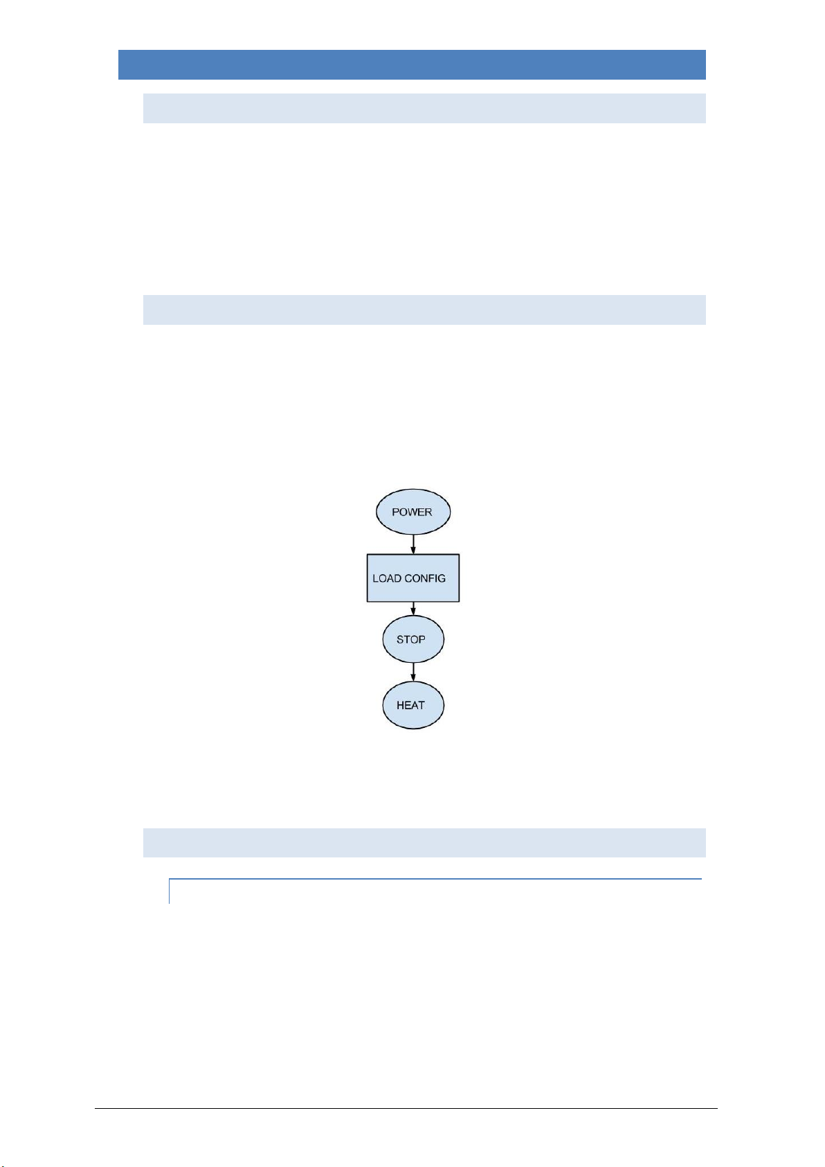
The Compact Heater implements MODBUS-RTU as a control-communications feature that allows its
operation and supervision tasks from a MODBUS automation environment. Preventive maintenance
and fault analysis is also possible thanks to the implementation of internal registers in the Compact
Heater with the more relevant operational and error events.
Whenever the Compact Heater is installed, you are not forced to connect it to a MODBUS system, as
far as you do not aim to control or supervise it externally. The Compact Heater can run in local mode,
as traditionally done, without using the MODBUS layer.
However, we expect that the implementation of MODBUS-RTU in the Compact Heater will open to our
advanced customers and partners a wide range of new opportunities and implementation scenarios
thanks to the simplicity and flexibility of the MODBUS-RTU layer.
Using a MODBUS-RTU message, the Compact Heater can report errors, historical data and so on, giving
to the user/installer a wide range of new features based in the automation of an already existing and
proved Compact Electric Heater.
1.2. BASIC CHARACTERISTICS
The MODBUS communication system provides a Master/Slave implementation among devices sharing
a physical connection. For the Compact Heater, the physical connection is a RS485 half-duplex serial
layer, which has been chosen among other options due to its wide implementation and roughness.
For the Compact Heater, a RS-485 half duplex wired connection has been implemented and the
Compact Electric Heater is designed to run in a single-master system. In this implementation, Master
and Slave figures has a clear role that is crucial to clear understand for a proper system
implementation.
Master Device: Device that controls the data exchange in the bus and, if necessary, implements co-
ordination tasks among different slaves (i.e. PLC Programmable Logic Controller, SCADA, etc.).
Slave Device: Devices connected to the bus that attends to the requests from the master, either
reporting information or executing tasks as per Master request.

© ASTRALPOOL 2016 ALL RIGHTS RESERVED. PROPRIETARY DOCUMENT.
6
2. ELECTRICAL CONNECTIONS
Image 1: electrical connection
Note: some manufacturers assign for the RS-485 port the “A”connection as a “+”, and “B”as a “-“,
while others reverses this nomenclature. The Compact Electric Heater uses the “A”as “+”, and the “B”
as “-”. Mind this aspect when connecting to the bus devices coming from different manufacturers.

© ASTRALPOOL 2016 ALL RIGHTS RESERVED. PROPRIETARY DOCUMENT.
7
3. CABLE CHARACTERISTICS
The recommended wiring for a MODBUS-RTU Communication is based in a linear structure, active bus
with termination at both ends. It is possible coupling and uncoupling of devices during operation
without affecting other devices. The wire shall be twisted and shielded according to EN 50 170.
The values of transmission rate supported for the device, allow maximum cable length of 1,200 m
without repeaters, or up to 10 km using repeaters, when installation is according to the standard.
For the balanced pairs used in an RS485-system, a Characteristic Impedance with a value higher than
100 Ohms may be preferred, especially for 19200 and higher baud rates.
4. BUS ISOLATION AND TERMINATION RESISTORS
If the communication bus is accessible for the user, it shall be double insulated. As far as in general the
accessibility of the bus to users will depend on each single installation, safety isolation has NOT been
implemented in the Compact Electric Heater physical bus layer. Moreover, for safety purposes, it is
recommended to ensure that other devices sharing this bus also implements this insulation.
Additionally, the use of bus insulated devices not only enhances the security level, furthermore
increases the equipment reliability, larger immunity to electromagnetic interference, longer life, higher
reliability, more stability over the range of temperatures.
Whenever single or multiple devices are connected sharing a bus physical connection, it is
recommended to use terminating resistors at the ends of the bus, even more when use large cable
length or high speed data rates. The terminating resistor is used to prevent an RF signal from being
reflected back from the end, causing interference. The terminating resistor must be in both ends of the
bus, connected in parallel (as shown in the image below). A typical value of this resistance is 120Ω,
0.5W. The value of the resistor must be the same in both ends. The terminating resistors are the
resistors 𝑅𝑇of the Image 3: terminating resistors.
Image 2: terminating resistors

© ASTRALPOOL 2016 ALL RIGHTS RESERVED. PROPRIETARY DOCUMENT.
8
5. BOARD AND PANEL INDICATORS
The Compact Heater includes a panel with capacitive buttons and OLED display to indicate its various
functions.
Image 3: keyboard panel

© ASTRALPOOL 2016 ALL RIGHTS RESERVED. PROPRIETARY DOCUMENT.
9
6. MODBUS FUNCTIONS
6.1. FUNCTIONS SUPPORTED
Please, be careful at the possible actuations, and make sure that the function used is the correct.
Functions are implemented according to the MODBUS-RTU standard described in
http://www.MODBUS.org/docs/MODBUS_Application_Protocol_V1_1b.pdf. In general registers are
unsigned 16 bit coded.
0x01 READ COILS
0x02 READ DISCRETE INPUTS
0x03 READ HOLDING REGISTERS
0x04 READ INPUT REGISTERS
0x05 WRITE SINGLE COIL
0x06 WRITE SINGLE REGISTER
6.2. EXCEPTION RESPONSES
Exception responses are implemented according to the MODBUS-RTU standard described in the
chapter MODBUS exception responses:
http://www.MODBUS.org/docs/MODBUS_Application_Protocol_V1_1b.pdf
The exceptions implemented are from 1 to 4 I 6.
Exceptions of type 4 are used to indicate that you are trying to use or activate a heater function that
cannot be used in the current configuration.
Exceptions of type 6 are used to indicate that the heater is in a transitory state and cannot answer with
information that is representative of the state of the heater to a request for information. The master
must repeat the operation after a few seconds.

© ASTRALPOOL 2016 ALL RIGHTS RESERVED. PROPRIETARY DOCUMENT.
10
7. DEVICE DESCRIPTION AND CONFIGURATION
7.1. GENERAL DESCRIPTION
In general, there is not check on the constancy of the values sent to specific registers. Therefore is the
operator responsibility to check that consistency.
In this manual, the numbers in hexadecimal have been represented with the format 0xZZ, where ZZ is
the number.
The register map that governs heater is explained below is in the chapter 0 Basic MODBUS-rtu Register
Map.
7.2 OPERATION DIAGRAM
When the system Powers ON, the Compact heater keyborad panel will turn ON. From this point the
Compact Heater will load the configuration parameters, such as setpoint temperature, temperature
units used and so on.
Finally the Compact Heater will remain in the idle state, waiting a request to heat water, if the
conditions in configuration parameters meet and the “on button is pushed”, the appliance will activate
the heater. The image 5 shows this flow.
Image 4 Operation diagram
7.3 ADDRESS AND BAUD RATE SELECTION
7.3.1 ADDRESS SETTING
The address of the Compact heater in the bus is set through the 0x00 Holding Register.
ID_Address: Address of the heater in the bus.
Factory setting: 0x07.
Suggested range: 0x07 - 0x0A.
The factory default for the Compact heater is 0x07. However you can change this value by writing this
holding register and as far as you check to not introduce collisions or conflicts with other slave’s
addresses.

© ASTRALPOOL 2016 ALL RIGHTS RESERVED. PROPRIETARY DOCUMENT.
11
Example: changing the ID address from 0x07 (default) to 0x08.
Transmit Message: 07 06 00 00 00 08 88 6A
Where:
07 is the slave address. (The actual ID address).
06 is the function used. Write Single Registers.
00 00 is the address of the first Holding Register to be written.
00 08 is the new ID address.
88 6A is the CRC.
7.3.2 BAUD RATE SELECTION
The Baud Rate selection of the serial communications with the Compact heater is set through the 0x01
Holding Register. By default, 9600 bps and 8E1 (8 data bits, Even Parity, 1 stop bit) is implemented.
However, 19200 bps, 1 and 2 stop bits with no parity are also supported. It allows us a total of six
different configurations.
The reason for supporting N2 frames is to keep the MODBUS standard requirement of sending eleven
bits per byte (1 start + 8 data + 1 parity + 1 stop). Whenever an 8N2 configuration is chosen, then 2
stop bits are introduced to keep the eleven bits per byte required by the standard.
Although 8N1 frames are also supported, keep in mind that with this selection you are not fulfilling the
MODBUS standard requirements as far as only ten bits per byte are used.
According to this, the baud rate and frame selection is completed defining the baud rate (in bauds),
number of data bits, parity and number of stop bits.
COM_Setup: Communication setup
Factory setting: 0 9600, 8E1
Supported values: 0 9600, 8E1
1 19200, 8E1
7.4 BROADCASTING
Broadcasting is not supported by the Compact Heater.

© ASTRALPOOL 2016 ALL RIGHTS RESERVED. PROPRIETARY DOCUMENT.
12
8OPERATION MODES
8.1 BASIC OPTIONS
In this section it is assumed that a successful connection has been established with the Compact heater
and therefore, address, baud settings and watchdog behavior has been already set.
The less significant bit corresponds to the bit 0, and the most significant bit corresponds to bit 15.
In section 9 a detailed description of all records defined in the Compact Heater can be found. This
section provides examples of how you can use MODBUS to remotely control and monitor the operation
of the Heater.
8.1.1 TECHNICAL CONFIGURATION OPTIONS
To complete the basic configuration of the Heater, we should choose the temperature set point. We
have to edit the Holding Register 0x24, and enter a value in Celsius degrees (°C) or Fahrenheit degrees
(°F), just keep in mind that the appliance has to be set on the same scale to prevent exceptions. If we
want to set a 28 ° C value, write the value 28:
07 06 00 24 00 1C C8 6E
Where:
07 is the slave address.
06 is the function used. Preset Single Register.
00 24 is the holding register to be written. 36 in decimal.
00 1C is the hexadecimal value equivalent to 28°C decimal value.
C8 6E is el CRC.
8.1.2 REQUEST WORD
Once we have made the heater configuration, we can send an order to power on the heater using the
Holding Register 0x21.
.bit 1 Sets temperature scale:
1=°C
0=°F.
.bit 8 Sets heater on or off:
1: On
0: Off
Example: Turn on the heater. So we must set the bit 8 to 1:
07 06 00 21 01 02 59 F7
Where:
07 is the slave address.
06 is the function used. Preset Single Register.
00 21 is the holding register to be written. 33 in decimal.
01 02 the order to power up the unit in hexadecimal; in binary would be 100000010
59 F7 is the CRC.

© ASTRALPOOL 2016 ALL RIGHTS RESERVED. PROPRIETARY DOCUMENT.
13
8.1.3 CHECKING STATUS
Once sent the power on command to the heater, it is possible via MODBUS, to monitor the operating
status of the heater. There are different levels of detail provided.
By reading the Input Register 0x00, we can examine the operation mode of the heater.
07 04 00 00 00 01 31 AC
Where:
07 is the slave address.
04 is the function used. Read Input Registers.
00 00 is the address of the first Input Register to be read.
00 01 is the number of records to be read.
31 AC is the CRC.
The heater response is:
07 04 02 01 02 B1 61
Where:
07 is the slave address.
04 is the function used. Read Input Registers.
02 is the quantity of bytes received.
01 02 is the state received, 100000010 in binary.
-Bit 8 is 1: The heater is on.
-Bit 1 is 1: =°C.
-Bit 0 is 0: There are no alarms.
B1 61 is the CRC.
By Input Register 0x02 we can access more detailed information about the internal state of operation
of the heater. See 8.1.5 pg.15.

© ASTRALPOOL 2016 ALL RIGHTS RESERVED. PROPRIETARY DOCUMENT.
14
8.1.4 TEMPERATURE PROBES READINGS
The values of the readings of the temperature probes installed in the heater can be read by the Input
Registers 0x07 inlet water temperature and 0x08, water outlet temperature.
Specifically, to read inlet water temperature, Input Register 0x07 is to be read.
07 04 00 07 00 01 80 6D
Where:
07 is the slave address.
04 is the function used. Read Input Registers.
00 07 is the address of the first Input Register to be read.
00 01 is the number of records to be read.
80 6D is the CRC.
Received response is:
07 04 02 00 12 B1 3D
Where:
07 is the slave address.
04 is the function used. Read Input Registers.
02 is the quantity of bytes received.
00 12 is the temperature received in degrees (hexadecimal). Equivalent to 18° in decimal.
B1 3D is the CRC.
To read outlet water temperature, Input Register 0x08 is to be read.
07 04 00 08 00 01 B0 6E
Where:
07 is the slave address.
04 is the function used. Read Input Registers.
00 08 is the address of the first Input Register to be read.
00 01 is the number of records to be read.
B0 6E is the CRC.
Received response is:
07 04 02 00 15 F0 FF
Where:
07 is the slave address.
04 is the function used. Read Input Registers.
02 is the quantity of bytes received.
00 15 is the temperature received in degrees (hexadecimal). Equivalent to 21° in decimal.
F0 FF is the CRC.

© ASTRALPOOL 2016 ALL RIGHTS RESERVED. PROPRIETARY DOCUMENT.
15
8.1.5 DIGITAL INPUTS
The status of the digital inputs of the heater can be monitored using the Input Register 0x02
07 04 00 02 00 01 90 6C
Where:
07 is the slave address.
04 is the function used. Read Input Registers.
00 02 is the address of the first Input Register to be read.
00 01 is the number of records to be read.
90 6C is the CRC.
The heater response is:
07 04 02 00 0F 71 34
Where:
07 is the slave address.
04 is the function used. Read Input Registers.
02 is the quantity of bytes received.
00 0F is the state received, 1111 in binary:
-Bit 3 is 1: Heating element #3# is on.
-Bit 2 is 1: Heating element #2# is on.
-Bit 1 is 1: Heating element #1# is on.
-Bit 0 is 1: There is water flow.
71 34 is the CRC.
The read states correspond to a heater that is warming since the water temperature is below the set
point.

© ASTRALPOOL 2016 ALL RIGHTS RESERVED. PROPRIETARY DOCUMENT.
16
8.1.6 REAL TIME ALARMS
The state of the alarms of the heater can be consulted in real time and available in 0x01 Input register.
This input register contains information about the status of alarms at that exact moment of time,
activating the corresponding bits by:
.bit 1 Overheating.
.bit 3 Water flow needed and not present.
.bit 14 Freezing risk.
For example:
07 04 00 01 00 01 60 6C
Where:
07 is the slave address.
04 is the function used. Read Input Registers.
00 01 is the address of the first Input Register to be read.
00 01 is the number of records to be read.
60 6C is the CRC.
Received response is:
07 04 02 00 08 30 F6
Where:
07 is the slave address.
04 is the function used. Read Input Registers.
02 is the quantity of bytes received.
00 08 is the status of the alarms. Binary equivalent is 1000:
-Bit 3 is 1: water needed and not present.
30 F6 is the CRC

© ASTRALPOOL 2016 ALL RIGHTS RESERVED. PROPRIETARY DOCUMENT.
17
8.1.7 LATCHED ALARMS
It is possible to view a report on the alarms produced so far. The Holding Register 0x20 contains
information about the status of alarms produced until that moment, activating the corresponding bit/s
by:
.bit 1 Overheating
.bit 3 Water flow needed and not present
.bit 14 Freezing risk
To check the status of the alarm memory, send the string:
07 03 00 20 00 01 85 A6
Where:
07 is the slave address.
03 is the function used. Read Holding Registers.
00 20 is the address of the first Input Register to be read.
00 01 is the number of records to be read.
85 A6 is the CRC.
Received response is:
07 03 02 40 08 00 42
Where:
07 is the slave address.
03 is the function used. Read Holding Registers.
02 is the quantity of bytes received.
40 08 is the state of the alarms memory. Binary equivalent is 100000000001000:
-Bit 3 is 1: water needed and not present.
-Bit 14 is 1: Freezing risk.
00 42 is the CRC
The values of active bits will remain in that state even after disarming the alarm from the keyboard of
the heater. To reset its value, do it by directly typing into Holding Register 0x20. It is also reset when
the heater loses electrical supply.
Example to reset alarm history:
07 06 00 20 00 00 88 66
Where:
07 is the slave address.
06 is the function used Preset Single Register.
00 20 is the address of the Holding Register to be written.
00 00 is the value to be written
88 66 is the CRC.

© ASTRALPOOL 2016 ALL RIGHTS RESERVED. PROPRIETARY DOCUMENT.
18
8.1.8 CHECKING COUNTERS
Using MODBUS it is also possible to check the status of operation counters of the heater. These
counters keep information regarding the number of operation hours of the heater, number of times it
has been powered off, number of times there has been an overheating alarm, or the total heating
hours. These counters, which are defined in a holding record type, can be set to 0.
Example query of the number of heater power offs:
07 03 00 30 00 01 84 63
Where:
07 is the slave address.
03 is the function used. Read Holding Registers.
00 30 is the address of the first Input Register to be read.
00 01 is the number of records to be read.
84 63 is the CRC.
Received response is:
07 03 02 00 05 F0 47
Where:
07 is the slave address.
03 is the function used. Read Holding Registers.
02 is the quantity of bytes received.
00 05 is the number of times the heater has been powered off.
F0 47 is the CRC.
Example query of the number of times an overheating alarm has occurred:
07 03 00 31 00 01 D5 A3
Where:
07 is the slave address.
03 is the function used. Read Holding Registers.
00 31 is the address of the Holding Register to be read.
00 01 is the number of records to be read.
D5 A3 is the CRC.
Received response is:
07 03 02 00 00 30 44
Where:
07 is the slave address.
03 is the function used. Read Holding Registers.
02 is the quantity of bytes received.
00 00 is the number of times an overheating alarm has occurred.
30 44 is the CRC.

© ASTRALPOOL 2016 ALL RIGHTS RESERVED. PROPRIETARY DOCUMENT.
19
9BASIC MODBUS-RTU REGISTER MAP
The table shown in this chapter is our exclusive and original register map with the name of the function
and their address.
To reset the alarm errors, it is necessary to reset it from the Holding Register 0x20 and not from Input
Register 0x01 due to, the Input Register 0x01 will reset when the current error alarm disappears. To
reset all the alarms, it is necessary to set to 0 the Holding Register 0x20.
Note: a disconnection of the power supply will also reset the latched alarms.
In the register map, in some cases the data is split in two parts due to the size of the information.
These parts are the high byte and the low byte. The high byte represents the more significant byte, and
the low byte represents the less significant byte.
9.1 HOLDING TYPE REGISTERS (READ) FACTORY SETTINGS.
We can read and write to the registers 0x00 and 0x01.
Name
Address
Initial
value
Information
ID_Adress
0x00
7
MODBUS slave address. The addresses assigned to the
heater are 7 to 10. Returns a type 3 exception if you want
to write a different value than 1..255.
COM_Setup
0x01
0
The configuration of the serial communication on the
MODBUS. Allowed values:
0: 9600, 8, E, 1
1: 19200, 8, E, 1
2: 9600, 8, N, 2
3: 19200, 8, N, 2
4: 9600, 8, N, 1
5: 19200, 8, N, 1
An invalid value generates a type 3 exception.

© ASTRALPOOL 2016 ALL RIGHTS RESERVED. PROPRIETARY DOCUMENT.
20
9.2. ALARMS & OPERATION HOLDING REGISTERS (READ/WRITE)
Name
Address
Initial
value
Information
Alarm historic
0x20
0
Contains information on alarms that have been activated
at some point. Must be reset by writing a 0 from the
MODBUS or removing electrical supply. Each bit has a
meaning associated with a type of alarm.
Bit
Alarm
0
1
Overheating alarm
2
3
Flow not present and needed
4
5
6
7
8
9
10
11
12
13
14
Freezing risk
15
Request_Word
0x21
8
It is the register that allows us to turn on or off the
heater. By default, the heater is off.
bit 0 Not used.
bit 1 1= °C
0=°F
bit 8 Manual On / Off
1: Turns heater on
0: Turns heater off
Set Point
temperature
0x24
20
Temperature set point for water. Invalid values return a
type 4 exception.
9.3. COUNTERS & TEST HOLDING REGISTERS (READ ONLY)
We can read a list of counters that gather useful information, this info can help the installation to
better understand a hypothetical problem.
Name
Address
Initial
value
Information
Start counter
0x30
0
Number of times the heater has received power supply.
Overheated
counter
0x31
0
Every time there is an overheating alarm this counter
increases. When desired, it can be put to 0.
Freezing risk
0x32
0
Every time there is a freezing risk alarm, this counter
increases. When desired, it can be put to 0.
Total Operation
time
0x33
0
Every hour of heating time, increases the counter by 1.
This manual suits for next models
4
Table of contents
Languages:
Popular Electric Heater manuals by other brands

Starlyf
Starlyf RADIANT HEATER instruction manual

Manrose
Manrose FAN6882 installation instructions

L.B. White
L.B. White H-17 Owner's manual and instructions

Heatscope
Heatscope SMARTBOX Original installation and instruction manual

Orbegozo
Orbegozo REW 500 instruction manual

VTS Medical Systems
VTS Medical Systems Volcano VR Mini Technical documentation

DeLonghi
DeLonghi RADIANT HEATER Instructions for installation and use

Nibe
Nibe ELK 42 Installer manual

Strend Pro
Strend Pro IFJ 02-400 instruction manual

Harvia
Harvia PC70HE Instructions for installation and use

Valor Fires
Valor Fires 809 Installer and owner guide

CONVECTAIR
CONVECTAIR APERO 7359 BB Installation & operating instructions