Chapter 1
Safety Precautions
This manual contains important safety information and instructions. Failure to comply with these
instructions can result in death, injury or permanent damage to this equipment and will void the
warranty.
Intended Use
This equipment is designed for use with standard adhesive and sealant materials with ash points
above 232 °C (450 °F). Use of ammable material or material not compatible with the
specications of this equipment can cause injury to operator and damage to equipment.
The manufacturer has designed this equipment for safe operation. Specied models are in
compliance with EN 60204-1:1997. However, heated thermoplastics and other hot melt materials
are dangerous and care must be exercised to ensure operational safety. Handling must be in
accordance with hot melt manufacturer specications. Never exceed the maximum application
temperature recommended by the adhesive manufacturer.
Dispose of hot melt properly. Refer to the Materials Safety Data Sheet (MSDS) of the hot melt for
recommended disposal methods.
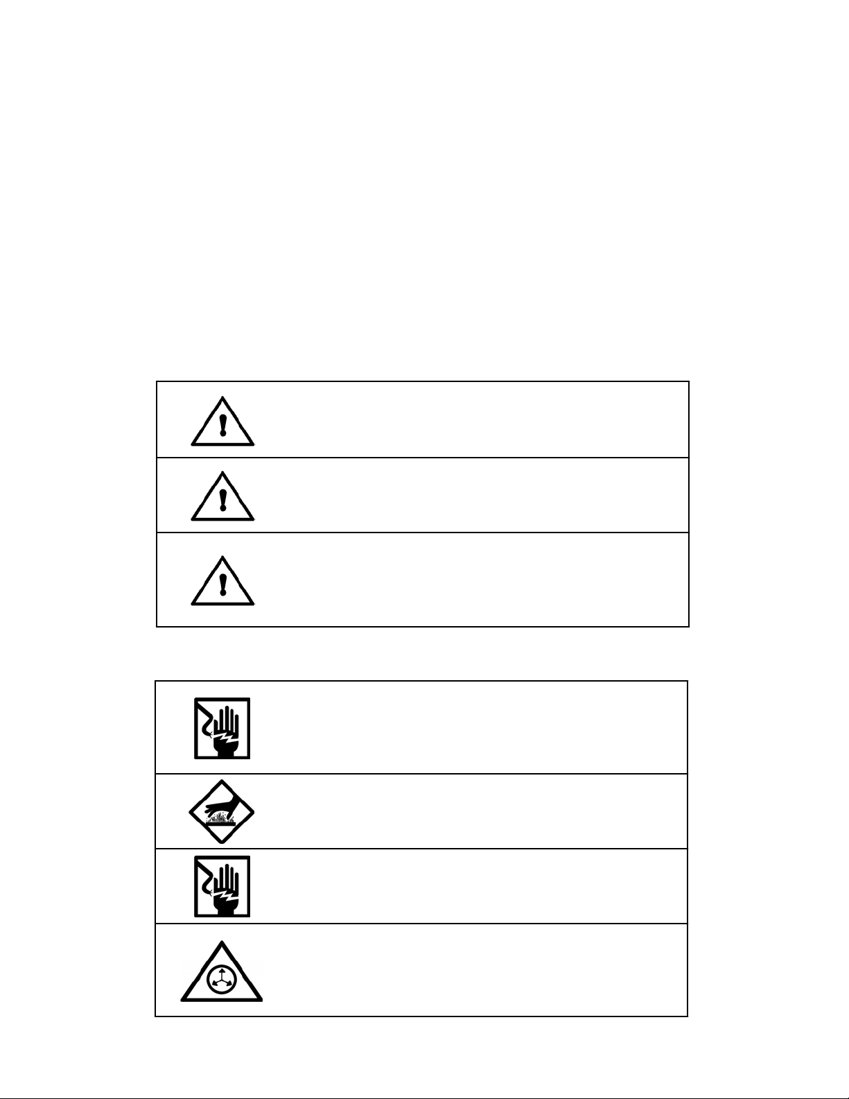
Personal Safety
Wear the following protection when working on or around this
equipment:
Always wear heat resistant gloves rated to 205 °C (400 °F) and allow all
system temperatures to stabilize below 193 °C (380 °F) before servicing.
Properly ventilate equipment according to MSDS of equipment. Trained
operators and service technicians should be aware of exposed surfaces of
the unit that cannot be practically safeguarded. These exposed surfaces
may be hot and take time to cool after the unit has been operating.
Keep parts of the body away from rotating parts. Do not wear loose Safety
Gloves, articles of clothing when operating or servicing units with rotating
parts. Remove wristwatches, rings, necklaces, or other jewelry and cover or
pin up long hair before performing any work on or with the unit.
Trained operators may perform only external equipment adjustments.
Trained service technicians must perform internal adjustments and service.
Electrical Safety
Determine voltage of this equipment before installation and conrm compatibility with available
power. Equipment must be connected to a properly grounded circuit and installed in accordance
with all applicable electrical codes. Ground fault protection must be provided in supply circuitry at
site installation. Models designed to EN60204-1: 1997 require power cords be approved to a
harmonized (HAR) standard and rated for 70 °C (158 °F). A HAR approved Type B plug and strain
relief for power cord are required to meet standard IEC 309. Power conducting wires must be
nominal 5.3 mm2 (10 AWG) maximum and nominal 2.1 mm2 (14 AWG) minimum.
©Astro Packaging Rev D D2-15 Manual-19600-10-D215 1-1