ATAGO PRM-100a User manual

3574-E16
In-line Refractometer
Instruction Manual
Cat.No.3574
PRODUCT REGISTRATION & WARRANTY CARD
https://www.atago.net/registration/
english/registration.php


1
CONTENTS
1. Precautions for Use···································································································2
2. Refractive Index and Brix(%)·····················································································7
(1)What is refractometer?················································································································ 7
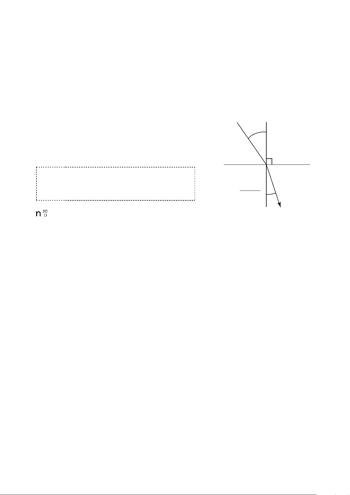
(2)What is the Refractive Index? ····································································································· 7
(3)Brix(%) scale ······························································································································· 7
(4)Temperature correction··············································································································· 7
3. Unpacking and Installation························································································8
(1) Unpacking··································································································································· 8
(2)Installation···································································································································· 8
4. Names and Functions of Components······································································9
(1)Detection Section (Fig. 4-1 and Fig. 4-2)···················································································· 9
(2)Display Section·························································································································· 10
5. Mounting the Detection Section ··············································································12
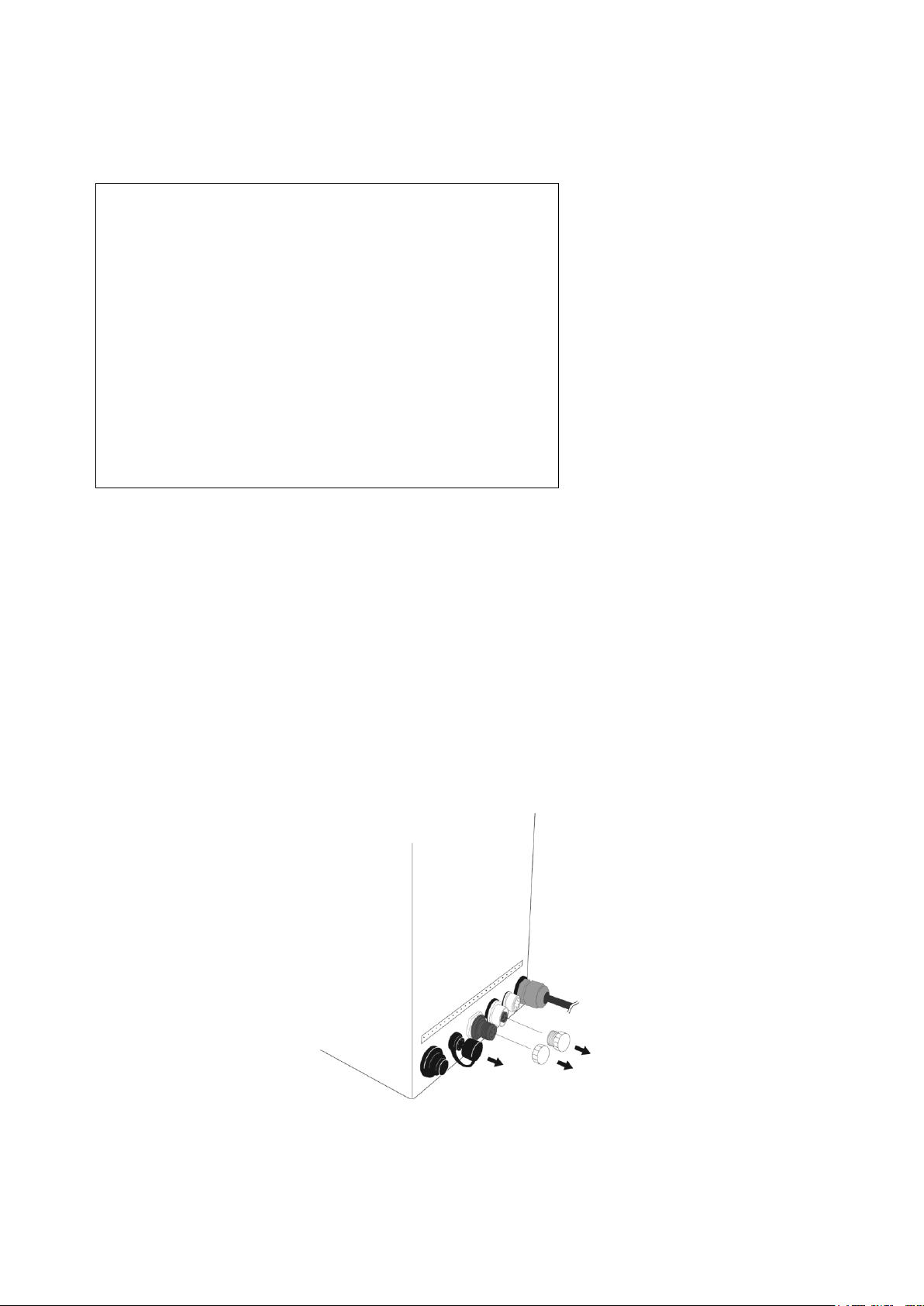
(1)Types of Sample Inlet Unit (Fig. 5-1) ························································································ 12
(2)Mounting the Sample Inlet Unit (Fig. 5-2)················································································· 13
(3) Mounting on the Piping (main) (in the case of L type)····························································· 14
(4) Mounting on the Piping (main) (in the case of straight type)··················································· 14
(5) Position of the thermo sensor ·································································································· 14
6. Mounting the Display Section··················································································15
7. Connecting the Detection Section to the Display Section·······································17
8. External Output ·······································································································19
(1)Recorder Output (Fig. 8-2 and Fig. 8-3) ··················································································· 19
(2)RS-232C Output························································································································ 20
(3) Alarm Output (high- and low-limiter output)············································································· 21
9. Turning On the Power·····························································································22
10. Setting Measurement Value Display Modes····························································23
(1) Common Operation·················································································································· 23
(2) Change from nD Mode to Brix ·································································································23
(3) Change from Brix Mode to nD ·································································································24
(4) Change from Brix Mode to Conc ····························································································· 24
(5) Confirmation of Measurement Values at Each Mode ····························································· 25
11. Setting Measurement SET UP Mode······································································26
(1) Calibration Procedure··············································································································· 26
(2) Setting alarms··························································································································· 28
(3) Setting recorder output············································································································· 29
(4) Setting Conc (User Scale)········································································································ 30
(5) Setting Decimal Place ·············································································································· 44
(6) Scale ON/OFF Set-Up ············································································································· 45
12. Measurement Procedure·························································································47
13. Cleaning the Prism··································································································48
14. Definitions of Error Messages·················································································49
15. Availability of Parts··································································································50
16. Specifications ··········································································································51
17. Dimensions··············································································································52
18. Repair Service and Warranty Period·······································································53
19. ATAGO CO.,LTD. Service Centers··········································································54

2
1. Precautions for Use
Introduction
Thank you for purchasing the "In-line refractometer PRM-100α". Before using your PRM-100α, read this
instruction manual carefully, and understand how to use it. After reading this manual, keep it on hand for future
reference.
In this manual "For safe use" describes the important items necessary for safety. Read it carefully.
For safe use --- Be sure to observe the following.
This operation manual describes the items which you are required to observe in order to use the
PRM-100αsafely, to prevent injuryto you and other people and damage to your property. The explanationof the
indications and symbols of those items are as follows. Understand them first and then read the following pages
to use your PRM-100α correctly.
Explanation of indications
WARNING
If this indication is neglected and the instrument is handled incorrectly, serious
injury or death may result.
CAUTION
If this indication is neglected and the instrument is handled incorrectly, injury
and/or property damage may result.
Explanation of symbols
This symbol denotes an item of which to be warned or cautioned.
The contents of warning are described in detail in or near the △.
This symbol denotes an action that must not be performed (a prohibited item).
The contents of prohibition are described in detail in or near the ○.
This symbol denotes an action that must be performed.
The contents of instruction are described in detail in or near the ●.

3
Handling of this instrument
WARNING
◇When measuring a substance harmful to the
human body, be aware of its properties and
wear protective gloves, mask, etc.
◇If the instrument begins to smell abnormally,
overheat, or emit smoke, turn off the power
switch and disconnect the power plug
immediately.
Fire or malfunction may result if the instrument is
continued to be used.
Ask yourATAGO distributor for an inspection.
◇Do not attempt to repair, modify, or disassemble
the instrument yourself.
Improper servicing may result in fire, electrical
shock, or burns.
◇If the instrument is dropped or is subjected to a
strong shock, have it inspected by an ATAGO
distributor.
Fire or malfunction may result if the instrument is
used.
CAUTION
◇Keep the detection section except for the
wetted sensor part away from water.
Do not operate the instrument while the
connecting ports of the display section is wet.
(The instrument is protected against
submersion in water, it may not be operated
submerged in water.)
Do not place the display section in places that
are frequently wet or have constant exposure to
water.
◇If this instrument is used to measure very hot or
highly acidic samples, the prism may be
damaged resulting in inaccurate measurements.

4
Handling of this instrument (Continued)
CAUTION
◇Do not pass corrosive materials over the prism
or through the sample inletunit.
◇Cleaning liquids up to 160 ˚C can be used for
CIP or SIP. The momentary difference between
the sample liquid temperature and the cleaning
liquid temperature must be no more than 80 ˚C.
When using cleaning liquids at temperatures
over 160˚C, the power switch must be turned
off.
◇If sample material has collected on the prism,
please refer to Page 48 "13.Cleaning the Prism"
of this manual for cleaning instructions.
◇Turn off the power switch before leaving the unit
out of serviced for an extended period of time.
◇When relocating the unit, pack it fully to guard
against shocks during transit and enclose it in
the corrugated fiberboard box in which it had
been delivered.
◇Carefully read this instruction manual and fully understand the function and operation of each part of the
instrument before use.
◇Inspect each part of the instrument for damage or defects that may have occurred in the shipping or
manufacturing process.
◇Check the necessary operations such as zero setting according to the instruction manual.
◇The manufacturer shall not be liable for any and all damages resulting from uses of the instrument that
deviate from those intended by the manufacturer, which are the measurement of Brix, sugar content, and
concentration of liquid solutions.
◇The prism is a consumable item and is not covered under warranty.
Special care should be taken to avoid scratching or damaging the prism.
◇The manufacturer shall not be liable for any effect the use of this instrument may have on the consumption or
application of the measured materials or related processes, etc.

5
Handling of plug
WARNING
◇Do not insert the power plug in an outlet other
thanAC100 to 240V.
Inserting the power plug in any other outlet may
resultin short circuiting the unit, smoking or fire.
◇Do not use the power cable and plug if damaged
or broken.
If used, fire, electrical shock, or burns mayresult.
For a new power cable and plug, contact your
ATAGO distributor.
CAUTION
◇Do not insert or disconnect the power plug with
wet hands.
◇Be sure to hold and pull the plug when
disconnecting the power cable from the outlet.
If the cable is pulled improperly, the plug may be
broken, and may result in fire or electrical shock.
◇Ensure the grounding pin is properly connected
when connecting the power cable to an AC
outlet.
◇The disconnecting device of the main unit is the
power cable.
Make sure that there is no obstacle in vicinity of
the plug.
Connecting Compontents
WARNING
◇Turn off the power switch and unplug the unit
from the AC outlet before connecting the
individual components with connecting cables.
Connecting components while the unit power is
on increases the likelihood of electrical shock.

6
Conditions to be observed when using
Environmental conditions
◇Use the instrument at an altitude below 2,000m (above sea level).
◇Use the instrument indoors.
◇Use the instrument where the temperature is between 5 to 40˚C.
◇Do not leave the instrument in a location exposed to direct sunlight or near a heating unit where the
temperature may rise.
◇Do not change the environmental temperature of the instrument suddenly.
◇Do not place the instrument in a place where it may be subject to strong vibrations.
◇Do not use the instrument where there is much dust.
◇Do not leave the instrument where the temperature is extremely low.
◇Do not leave the instrument in a damp place.
◇Do not place or drop heavy objects on the instrument.
◇Use this instrument under the condition where humidity is 80% at 31˚C or lower, falling linearly to 50% at
40˚C.
◇Main supply voltage fluctuation should not to exceed ±10% the nominal voltage.
◇Installation categories (Overvoltage Categories) : ll
◇The pollution degree is 2 (according to IEC60664).
Handling
◇Do not drop the instrument or subject it to any strong shock.
◇The power cable may be damaged by:
●
Bending the cable.
●
Pulling the cable.
●
Twisting the cable.
●
Placing the cable under heavy objects.
●
Catching the cable between objects.
Daily maintenance
◇If the instrument becomes dirty, wipe it with a soft cloth.
◇Do not use benzine, paint thinner, etc. to clean the instrument.

7
2. Refractive Index and Brix(%)
(1)What is refractometer?
When a straw is placed into a glass filled with water, the straw appears to bend.When a straw is placed into
a glass filled with sugar water, the straw appears to bend much more sharply than in the case of water
alone.
This phenomenon is known as the refraction of light. The refractometer is an instrument that measures the
Refractive Index by utilizing this principle (the Refractive Index increases in proportion to the concentration
of the solution), and was developed by Dr. ErnstAbbe at the end of the 19th century.
(2)What is the Refractive Index?
If the Refractive Index of air under atmospheric pressure is 1, then
when light enters medium χ, the ratio of the sine of the incident
angle αmeasured against the phase boundary to the sine of the
refracting angle βis called the Refractive Index of the mediumχ.
The Refractive Index varies with the wavelength of light and
temperature and is represented as follows:
nt
D
n : Represents the Refractive Index
t : Temperature (˚C)
D : D-line of natrium (589nm)
For example,Refractive Index of water at 20˚C under the D-line is:
= 1.33299:
(Generally expressed as nD = 1.33299.)
mThe Refractive Index is based upon the supposition that the Refractive Index in a vacuum is 1 and is
called the absolute Refractive Index. Generally, however, this index is seldom used.
(3)Brix(%) scale
The PRM-100α is programmed with the Brix(%) scale, based on the Refractive Index of water (nD =
1.33299) as the reference (0%). The Brix(%) scale represents the weight of sucrose expressed by
percentage (sucrose weight in grams contained in 100 grams of sucrose solution).
Therefore, this scale corresponds with the sucrose concentration. However, most samples are comprised
of ingredients other than sugar. The total concentration of these ingredients is represented by the Brix(%),
so this makes the Brix(%) scale a practical tool for measuring concentrations.
mThe Brix(%) scale is recommended by ICUMSA (International Committee of Uniform Method of
SugarAnalysis) and is expressed in % mas (Sucrose) in international units (SI unit).
(4)Temperature correction
TheRefractive Index of a substance varies with temperature. Thus, when using a refractometer to measure
the Refractive Index of a liquid, the measurement value will vary with the sample temperature.
The Brix or concentration value displayed by this product is automatically compensated by the internal
software based on the measured temperature and the same value is always displayed as if measurements
were made at 20˚C (in case of a sample temperature of 5 to 100˚C).
Air
Medium χ
n=1
α
β
nχ=
sin α
sin β

8
3. Unpacking and Installation
(1) Unpacking
①Unpack the unit and visually check for any damages that may have occurred during transit.
②Make sure that the following components are included:
PRM-100α detection section .................................1
PRM-100α calculation display section ..................1
Detection section - display section connecting cable
(hereinafter the DS-2 cable) ..................................1
Recorder output cable (4-20mA)...........................1
3K clamp band 3S..................................................1
O-ring (Silicon) .......................................................1
O-ring (EPDM)........................................................1
Plain washer...........................................................4
Hexagon socket head bolt
(cross-recessed for assembling a spring washer)2
Instruction manual (this manual)...........................1
Inspection certificate..............................................1
NThese components are available with PRM-100αand built to standard specifications.
(2)Installation
mRemove the socket caps from the display section (three caps) to access the terminals (Fig. 3-1).
①Run the unit from a power supply of 100VAC to 240VAC, 50/60Hz.
②Install the unit in an ambient temperature range of 5 to 40 ˚C.
③This unit contains precision components.
Avoid installing this unit in places that are exposed to direct sunlight or near a heat source, or where dust
or corrosive gases may accumulate.
④Install this unit in a location that is protected from strong vibration.
Exercise care during installation to avoid any impact or shock to the instrument, as such stress may affect
the performance of electronic components.
Fig. 3-1

9
4. Names and Functions of Components
(1)Detection Section (Fig. 4-1 and Fig. 4-2)
①Prism
Sample material contacts the prism surface to allow for the measurement of its refractive index, Brix
and/or concentration.
②Sample inlet unit mounting part
Mount the sample inlet unit on this part.
③Detection section - Display section connection terminal
Connect the DS-2 cable to this terminal.
④Air cooling fin
Dissipates heat to preserve the unit's electronic components when measuring high temperature samples.
⑤Mark to show the position of the thermo sensor.
Fig. 4-1
Fig. 4-2
⑤
③
①
②
④

10
(2)Display Section
(2-1) Operator section (Fig. 4-3)
①START/STOP key
Start or stops measurement (turning the
power on automatically begins
measurement).
②SCALE key
Chooses from among the measurement value
display modes nD (refractive index), Brix
(sucrose readingscale)andtheSETUPmode.
③ENTER key
Used to carry out reference level adjustment
and manipulate the SETUP mode.
For operating instructions, see the respective
items.
④← →keys
Cursor movement keys.
Use to move the digit position when setting a
numerical value in the SETUP mode.
The cursor is positioned on the blinking digit.
⑤↑ ↓keys
Numerical value change keys.
Use to change the numerical value in SET
UP mode.
⑥Measurement indicator
Indicates the current mode of measurement;
that is continuous or halted.
During use, the yellow light is blinks.
⑦SET UP mode indicator
Yellow light will be turned on at the SET UP
mode.
⑧H.over and L.over displays
If a high-limit or low-limit alarm is set in the SET
UP mode and then the high or low limit is
exceeded, the corresponding display
illuminates.
⑨Temperature display
Displays the temperature of the prism during
measurement.
⑩Measurement value display
Displays measurement or set value digitally.
⑪Mode display
Displays the mode in which numerical values
are shown on the measurement value display.
Calculation display section front view
Fig. 4-3
⑤
②
③
⑥
⑧
⑩
⑪
⑨
⑦
④
①

11
(2-2) Rear section (Fig. 4-4)
①Power key
Press to turn on the calculation display section.
②Alarm output terminal
Use to handle alarm signals.
③RS-232C output terminal
Use to connect the calculation display section to a personal computer.
④Recorder output terminal
Use to connect the calculation display section to a recorder.
⑤Detection section - display section connection terminal:
Connect the DS-2 cable to this terminal.
⑥Power cable
Insert into a 100VAC to 240VAC outlet.
Calculation display section rear view
Fig. 4-4
①
③
④
⑤
⑥
②

12
5. Mounting the Detection Section
WARNING
◇Turn the power switch on the display section to OFF and unplug it from the
AC outlet prior to mounting the detection section.
Mounting the detection section with the unit turned on may increase the
likelihood of electric shock.
CAUTION
◇Make sure that the piping and equipment are clear of any fluid before
mounting the detection section on the piping and equipment.
(1)Types of Sample Inlet Unit (Fig. 5-1)
Two types of sample inlet units are available as pipe fittings: straight type and Ltype.
The straight type should be installed on straight sections of piping.
The Ltype inletshould serve as the joining piece for piping intended to align in an Lshape (Fig.5-4 on page
14).
There are three ways to connect a sample inlet to a pipe: IDF/ISO clamp union (ferrule), IDF/ISO screw
union (screw), and JIS Flange.
Other sample inlets available include small diameter series compression fitting (outer diameter 10mmφ)
and hose connector (outer diameter 12mmφ).
Fig. 5-1
Straight type
L type
Compression Fitting 10mmφ
Hose connector 12mmφ

13
(2)Mounting the Sample Inlet Unit (Fig. 5-2)
Fit the sample inlet unit into the leading section of the detection part, and secure the sample inlet unit with
the attached clamp and O-ring provided.
Fig. 5-2
Support of detection section
Since the detection section weighs 3.2kg, it may not be
supported by connection with the sample inlet unit alone.
Therefore, support the detection section, as shown below.
If you cannot get the support, we will supply the following
parts.
・Pipe hanger (RE-67157)
・Hanger pin (RE-67156)
・Stand (RE-67155)
For the support bar, prepare a pipe having an outer diameter
of 19.0mm and an inner diameter of 16.0 to 17.0mm.
Fig. 5-3
⑤
Clamp
O-ring (silicon or
EPDM)
O-ring
(silicon or
EPDM)

14
(3) Mounting on the Piping (main) (in the case of Ltype)
Mount the detection section on the piping, observing the flow direction of the fluid to ensure it will hit the
prism surface of the detection section (Fig. 5-4).
Fig. 5-4
(4) Mounting on the Piping (main) (in the case of straight type)
When mounting the detection section to the piping, keep it positioned parallel to or below the piping to
ensure the flow of sample passes over the prism.
Mounting the detection section as shown in Fig. 5-5 is not advised, as low pressure or flow rate may
prevent the sample from contacting the prism sufficiently, interfering with measurement.
Fig. 5-5
(5) Position of the thermo sensor
There is a built-in thermo sensor near the prism.
As the position of the thermo sensor is marked (Fig. 5-6), mount the detection section to keep the mark
upstream in case the sample temperature widely varies.
Fig. 5-6
Mark to show the position
of the thermo sensor.
Top
Fluid flow
Fluid flow
Bottom
Fluid flow

15
6. Mounting the Display Section
WARNING
◇Turn the power switch of the display section to OFF and unplug it from the
AC outlet prior to mounting the detection section.
Mounting the detection section with the unit turned on may increase the
likelihood of electric shock.
It is recommended that the display section is mounted in a control box.
The display section is equipped with a wall-mount handle on the rear face, allowing the part to be mounted
to a wall surface (Fig. 6-1).
When mounting the display section on a panel, use up to two flat washers to adjust the thickness of the
panel as needed and bolt the display section.
The table assumes panel thicknesses of 1 to 5mm (Table 6-1).
Fig. 6-1
Mounting bolt M6×12
Plain washer
Panel surface
Mounting bolt M6×12
Plain washer
Panel surface
Cap screw M4×8SW, 8pcs
Unit front
Panel cut dimensions
182
210
2-φ6.5
224
+1.0
-0
+1.0
-0

16
Fig. 6-2
Table 6-1
Panel thickness
Plain washer
Schematic
1mm
2pcs
2mm
2pcs
3mm
1pcs
4mm
1pc
5mm
0pc
Hexagon bolt M6×12
Plain washer
Spring washer
1.9
12
1.6
Accessories:
Hexagon bolt··················2
Plain washer···················4
φ11.5

17
7. Connecting the Detection Section to the Display Section
WARNING
◇Turn the power switch of the display section to OFF and unplug it from the
AC outlet prior to attaching or detaching the DS-2 cable to or from the
terminal.
mRemove the socket caps from the display section to access the terminals (Fig. 7-1).
After mounting the detection section on the piping, connect it to the display section with the DS-2 cable
(included) (Fig. 7-2).
Fig. 7-1

18
Fig. 7-2
Detection section
DS-2 cable for connecting the
display and detection sections
Back of the calculation display section
Front of the calculation display section
This manual suits for next models
1
Table of contents
Other ATAGO Measuring Instrument manuals

ATAGO
ATAGO PAL-Easy ACID21 User manual

ATAGO
ATAGO PAL-Easy ACID101 User manual

ATAGO
ATAGO PAL-HIKARi 5 User manual

ATAGO
ATAGO WM-7 User manual

ATAGO
ATAGO PAL-07S User manual

ATAGO
ATAGO PAL-121S User manual

ATAGO
ATAGO PAL-03S User manual

ATAGO
ATAGO Po-1 User manual

ATAGO
ATAGO PAL-BXISALT User manual

ATAGO
ATAGO PAL-Easy ACID40 User manual
Popular Measuring Instrument manuals by other brands

JDS Uniphase
JDS Uniphase FBP Series user manual

PCB Piezotronics
PCB Piezotronics IMI SENSORS 626B13 Installation and operating manual

KROHNE
KROHNE OPTISONIC 6300 F Ex Series quick start

Anritsu
Anritsu Lightning 37 E Series Maintenance manual

iET
iET PRS-300 Series Operation manual

Valore
Valore AC154 instructions