TCI Library- http://www.telephonecollectors.info/
BELL
SYSTEM
PRACTICES
AT
&
TCo
Standard
SECTION
502-543-400
Issue 5,
December
1980
SERVICE
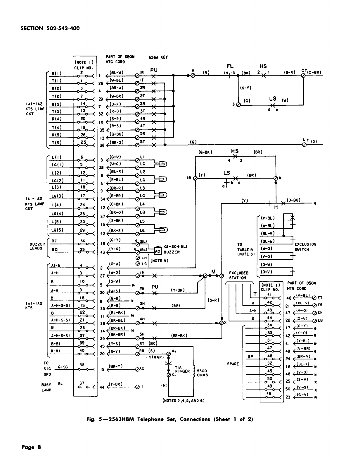
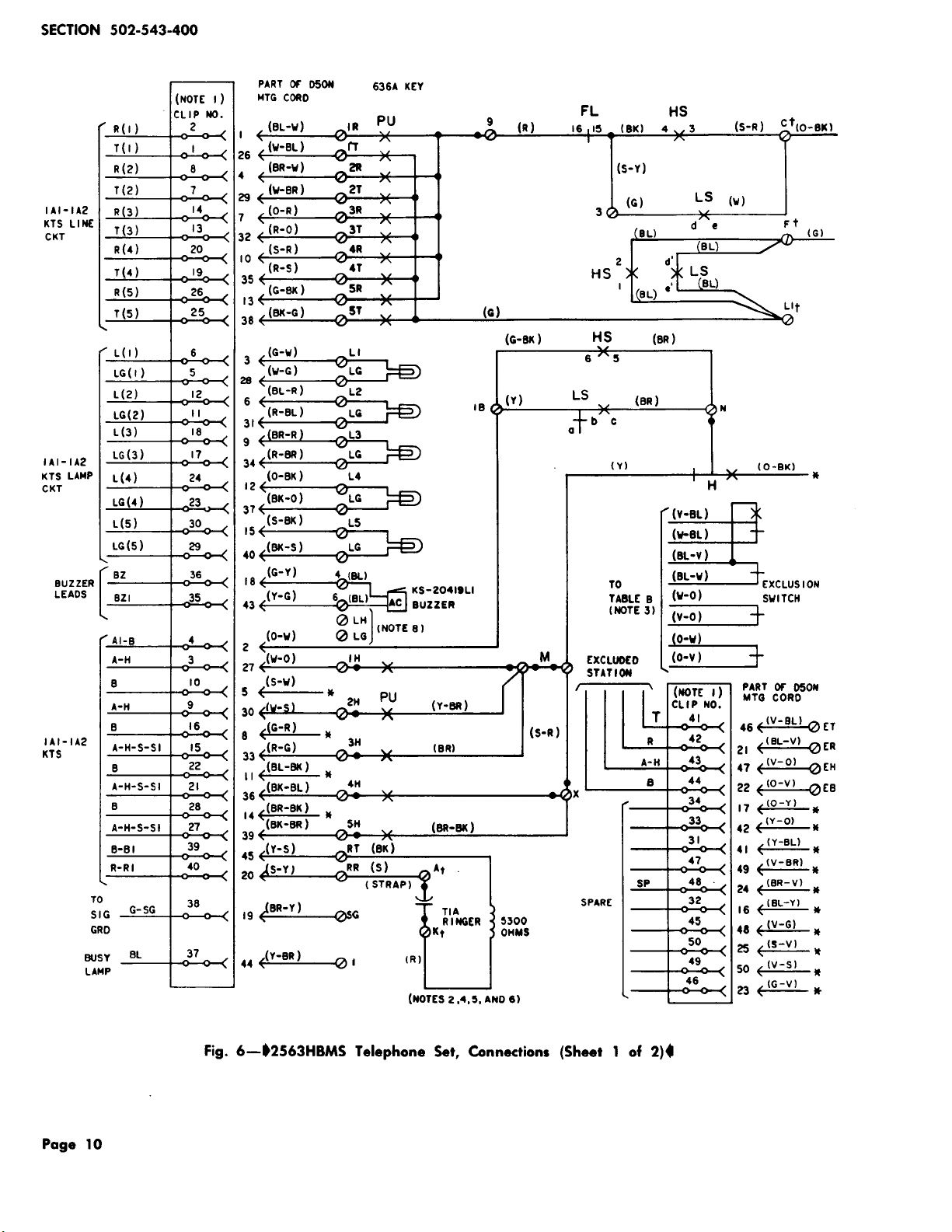
2563HB, 2563HBM, AND 2563HBMS
TELEPHONE
SET
MAINTENANCE AND CONNECTIONS
1.
GENERAL
1.01 This section contains information for
the
2563HB (MD),
2563HBM
(MD), and 2563HBMS
telephone sets equipped with headset jacks
and
12-button TOUCH-TONE® dial for use with optional
operator's headset.
1.02
This section is reissued to:
• Add
the
2563HBMS telephone
set
• Show 2563HBM telephone
set
MD
• Add information on
the
D-181006
Kit
of
Parts
(contains
an
840364376 polarity
guard
and installation instruction sheet), Table
A.
2.
MAINTENANCE
A. Replaceable
Components
2.01 Field replaceable
items
are
listed
under
identification in the appropriate Reference
section in Division
502.
2.02
Maintenance of
handsets
and
ringers
is
outlined in sections covering these components.
B.
Loose
Card
Retainers
2.03
The 812558039 (P-25E803)
and
802695619
(P-269561)
are
nonadjustable card retainers.
The P-25E785 (MD) card
retainer
is replaced by
812558039 (P-25E803)
..
2.04
If
P-25E785 (MD)
card
retainer
becomes
loose on the faceplate
and
the
number
card
or
designation
strip
slips, they can be tightened
as
follows.
(1) Remove faceplate from set.
(2) Remove card
retainer
from faceplate.
(3) Bend the four
arms
of the
retainer
so
that
more pressure will be applied to the number
card
and
designation strip. The bends should
be made approximately 1/2-inch in from the tabs
on
the
ends of the
arms
and
in the opposite
direction from
the
factory bent tabs.
(4)
Install
the card
retainer
on the faceplate
and
insert
the number card and designation
strip.
(5)
Install
faceplate on telephone set.
Note:
If
adjusting
the
arms
of
the
retainer
does not
result
in sufficient holding power,
replace the card retainer.
C.
Removing
and
Replacing Housing
2.05
Sets without exclusion.
(a)
To
remove housing, loosen captive screws
in base of set. Lift housing up
and
toward
front
of set.
(b) To replace housing, guide lower front of
housing over pushbuttons, align housing with
base of set,
and
gently press housing into place.
Tighten captive screws in base of set.
2.06
Sets with exclusion.
(a)
To
remove housing, pull up exclusion plunger
to its operated position, loosen captive screws
in base of set, and lift housing up and toward
the
front
of set.
(b)
To
replace housing, guide lower
front
portion
of housing over pushbuttons, align housing
NOTICE
Not for use
or
disclosure outside the
Bell System except under written agreement
Printed
in U.S.A.
Page
1