Atec A675STS User manual

Tilting, Swiveling & Rotating
Flat Panel Wall Mount
• Supports most 40”- 80” Flat Panel TVs
Model: A675STS
+5 to -5
+5 to -15
For technical assistance or troubleshooting
please call 1-800-936-1168
This product Wall Mount frame is intended for use only with an apparatus which has a maximum weight of 132 lbs. See apparatus
instructions. Using with an apparatus heavier than the maximum weight indicated may result in instability and cause possible
injury.
READ THIS FIRST
Read this entire manual! Do not attempt to install this product if you do not understand the instructions. Contact a qualified
mount installer if you have any doubts about a safe and secure mount installation, or if you are not sure what specific wall
materials you are attaching this mount to. Check all the parts carefully to make sure there are no missing or damaged parts.
Improper installation may result in damage to your TV, property, and personal injury.
• Maximum Weight Capacity: 132 lbs.
• Supports VESA Sizes up to 600x500

This product is intended only to mount a television of the indicated size and weight. Using this
product to mount televisions heavier than the maximum weight capacity can damage equipment
and cause personal injury.
Schoenfeld International Inc. and ATEC are not responsible for personal injury or product
damage due to mishandling, incorrect mounting, incorrect assembly, or incorrect use of this
product.
How and where you use your television wall mount is extremely important for Child Safety
As you set up and use your new product, keep all of these safety tips in mind.
• One size of TV wall mount does not fit all TVs. Use only a TV wall mount rated for the weight
of your TV and the size of your screen. Your TV wall mount assembly instructions contains
specific information on the maximum weight and screen size combination that your wall
mount can safely support. Do not exceed the maximum weight of screen size for any TV wall
mount.
• Carefully read all of enclosed instructions for proper use of this product. If you have any
doubts about safe and secure assembly, please contact a professional.
• Don’t let children climb on or play with mounts or TVs.
• Remember that children can become excited while watching a program, especially on a
“larger than life” TV. Make sure to place or install the TV wall mount where it cannot be
pushed, pulled on, or knocked down.
• Make sure that you route all cords and cables so that they cannot be pulled or grabbed by
curious children.
Always wear safety goggles to when drilling or installing hardware.
Tools
For your convenience, we have included an allen wrench with this mount. For the best assembly
experience and mounting safety, we always recommend using full-size tools for each assembly
step.
Below is a recommended tool list you will need for proper and safe installation. See applicable
warnings in this manual about certain types of mounting surface materials and the special hardware
and tools that should be used.
• Drill with a specific size drill bit to pre-drill holes in the wall
• Stud finder
• Tape measure
• Pencil
• Screw drivers
• Socket wrenches
• Small hammer
• Safety goggles

Wall Mount Bracket
M4x30mm bolts
M5x20mm bolts
M5x30mm bolts
22mm Spacers
17mm Spacers
M8x45mm Bolts
M8x25mm Bolts
M4x20mm bolts
M6x25mm bolts
M6x40mm bolts
M4/M5 Washers
M6/M8 Washers
Socket Tool
H
2
3
Allen Wrench
1
F
B64
A
1
C
E
4
I
J
12
1
4
6
K
L
4
4
4
D
M
4
N
O
P
Q
4
4
Wall Mount
R
Brackets
Security Bracket Clamps
Long Bolts
Long Bolt Washers
Concrete Anchors
1
2
24
4
4
Security Bracket Clamp Screws
6
G4Level (Attached to Wall Mount)
1
Concrete Anchors
Ax6 Bx6 Cx6
Long Bolts
Long Bolt
Washers
Qx4
Security Bracket
Clamp Screws
M5x12mm
x14
Allen Wrench with Phillips End
3
Security Bracket Clamps
x2
2
x2
1
x1 R-Level
x25
Mounting Plate
Side Pieces
S 4 Side Piece Screws
Sx4
Side Piece
Screws
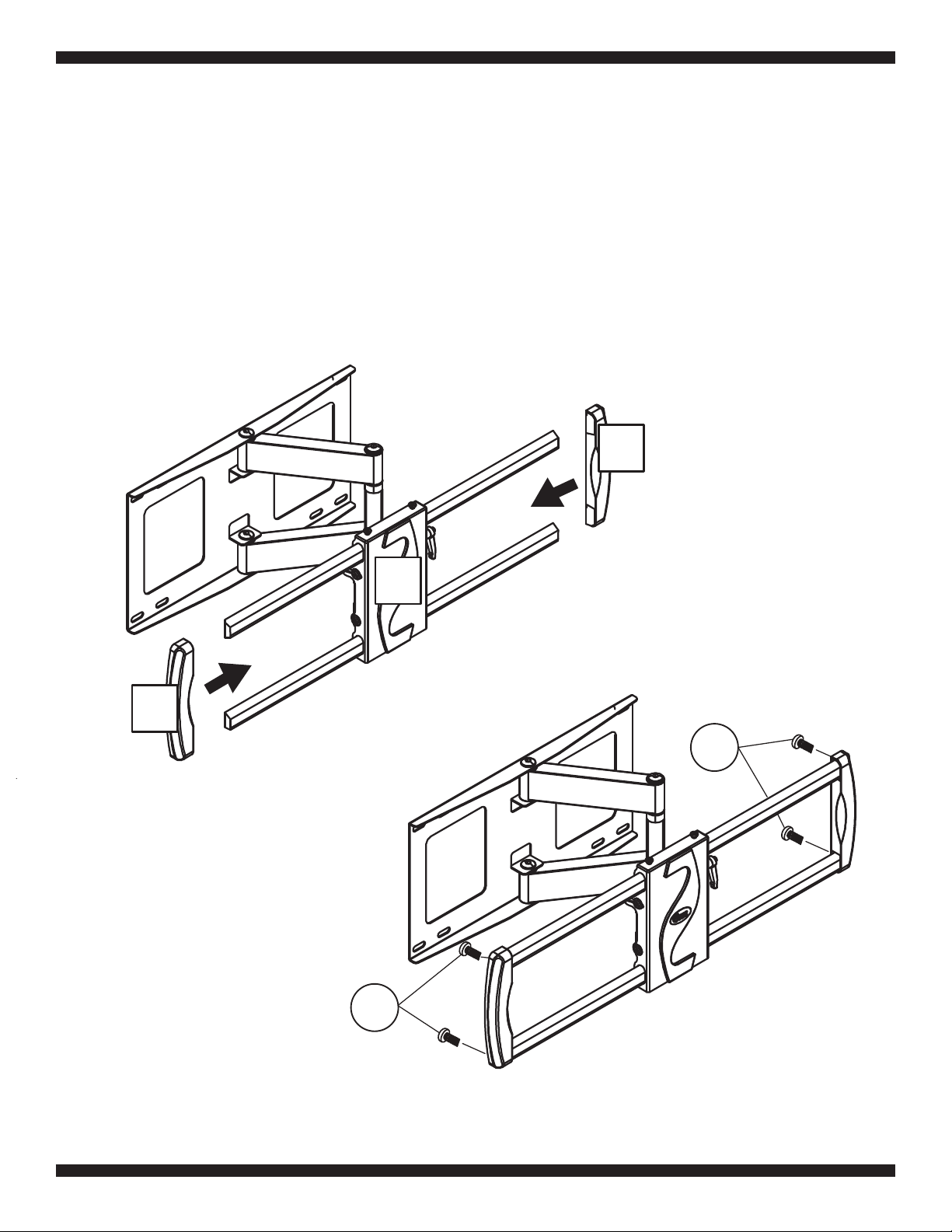
Slide the Mounting Plate Side Pieces (5) onto the ends of the Wall Mount (1).
4
Step 1: Attach the side pieces to the mounting plate
1
5
5
S
S
Secure the Mounting Plate Side Pieces (5) to the Wall Mount (1) using the Allen Wrench and
the Side Piece Screws (S).
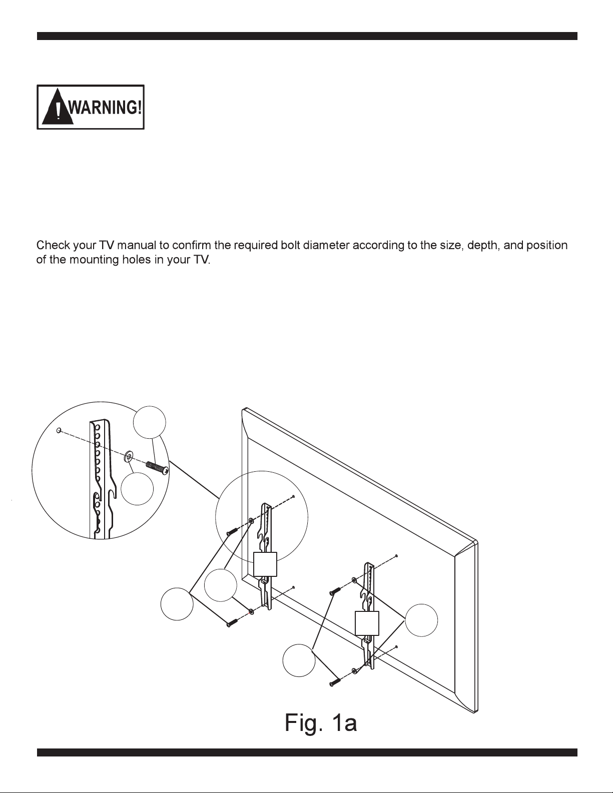
Attach the Brackets (2) to the rear of the TV using four of the Bolts (D-K) with the proper size
Washers (N-O) as shown in Fig. 1a. Make sure to use the same bracket holes for each side to insure
the Brackets (2) are centered top-to-bottom. Tighten using the Allen Wrench (4). Do not over tighten.
Do not force the bolts into the mounting holes on your TV. Do not use an electric drill to
tighten these bolts on your TV. This could damage the equipment or cause personal injury.
CAUTION: Do not place the TV face down on a hard surface when installing the mounting plate
on the TV. Placing the TV face down on a hard surface can result in equipment damage. Use a
blanket or other suitable surface.
If your TV has a flat straight rear, and your screen size is 55” or less, spacers are most likely not
necessary.
The Brackets (2) must be installed on the TV with the hook on each bracket facing down.
N-O
5
D-K
D-K
N-O
2
2
N-O
D-K
Step 2: Attach the left and right brackets to your TV

Fig. 1b
Attach the TV Bracket to the rear of the TV cont’d
Fig. 1c
D-K
L-M
N-O
If your television has a curved back, and the mounting holes are recessed (Fig 1b) spacers are
required. Install the proper size Spacers (L-M) between the TV rear and the bracket structure as
shown in Fig 1b. to make sure the Brackets (2) extend past the rounded portion of the TV. Then use
the selected Bolts (D-K), Washers (N-O), and the Allen Wrench (4) to attach the bracket structure
(with the spacers between the bracket and the TV) to the TV as shown in Fig 1c. Make sure the
bracket structure is properly aligned on the rear of the TV and securely tighten the bolts. Do not over
tighten.
Fig. 1d
6
N-O
L-M
D-K N-O
L-M
2
D-K
L-M
7
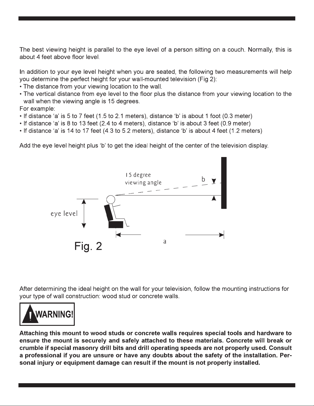
Step 3: Find and mark the best position for the wall mount on the wall
Step 4: Attach the wall mount to the wall

Fig. 3a
2-1/2” (65mm)
Fig. 3b
Fig. 3c
8
1. Use a pencil, awl, or a nail to mark the location of the wall stud centers (Fig 3a) after locating the
stud with an electronic stud locator. The distance between the marks should not be less than 16
inches (Studs must not be less than 16 inches (40.6cm)
2. Place the Wall Mount (1) flat against the wall with the center of the mount in the desired location,
aligning the holes in the mount with the studs (Fig 3b). Use the wall mount plate as a template to
mark the location of the four mounting holes on the wall. Make sure that the mounting holes are
level and are parallel using the built-in level on the front of the Wall Mount (1).
3. Use 3/16” (5mm) drill bit to pre-drill holes at least 2.5” (65mm) deep at the marked locations.
4. Use a wrench, the four Long Bolts (A), and Washers (C) to attach the wall mount to the wall. Do not
use wall anchors in wood stud walls.
5. Use the Level (R) placed on the front of the mounting plate to level the wall mount, repositioning as
necessary, then firmly tighten the bolts. Do not overtighten.
1
C
C
A
A
R

2.5” (65mm)
Fig. 3d
Fig. 3e
Step 5: Hang the television display
9
1. Place the Wall Mount (1) flat against the wall in the desired location. Use the wall plate as a
template to mark the location of the four mounting holes on the wall. Make sure that the mounting
holes are level and parallel. Make sure the horizontal holes are no closer than 16”.
2. Use 3/8” (10mm) drill bit to pre-drill four holes at least 2.5” (65mm) deep (Fig 3d) at the
marked locations.
3. Insert a Wall Anchor (B) into each pre-drilled hole and lightly tap it with a hammer until the wall
anchor is flush with the wall.
4. Use a wrench, the four Long Bolts (A), and Washers (C) to attach the wall mount to the wall with
the Wall Anchors (B) (Fig 3f).
5. Use the Level (R) placed on the front of the mounting plate to level the wall mount, repositioning as
necessary, then securely tighten the bolts.
C
Fig.3f
Concrete wall
C
A
A
B
A large television requires two people to lift. Schoenfeld International Inc. and ATEC are not
responsible for equipment damage or personal injury due to mishandling.
R
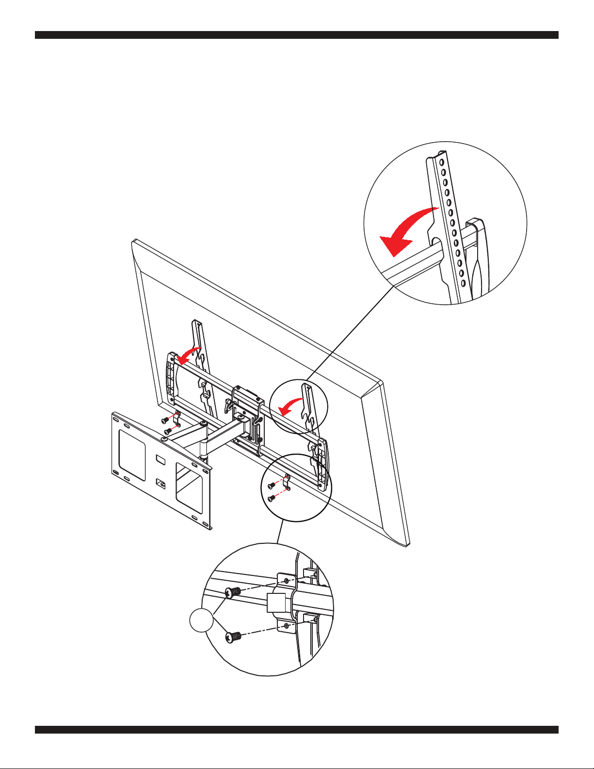
1. Lift the Television display with the brackets attached and carefully hang the top hook of the
Brackets (2) over the top bar of the Wall Mount (1) as shown in (Fig. 4a). Carefully swing the display
down so the lower part of the Brackets (2) fit over the lower bar of the Wall Mount (1).
2. Securely attach the Security Bracket Clamps (3) to the Brackets (2) using the Security Bracket
Clamp Screws (Q) and the phillips end of the Allen Wrench (4)(Fig. 4b).
Fig 4a
10
Fig 4b
Q
3

Step 6: Adjusting the Tilt
1. The Handle on the front of the Wall Plate mount arm is
used to adjust the tilt angle of the TV to your desired
angle as shown in (Fig. 5d).
2. This handle is a tension lever. To loosen the tilt
adjustment, turn the handle counterclockwise until the
handle hits the Wall Plate (1) and can turn no more.
Then pull the handle away from the mount arm to release
the spring as shown in Fig. 5a, and while holding the
handle away from the mount arm, turn the handle
clockwise (Fig. 5b) and release the handle to engage
the spring. Now you can turn the handle further
counterclockwise to loosen the tilt adjustment more.
3. Adjust the tilt angle of the TV to your liking and tighten
the handle.
4. To tighten this spring loaded handle and lock in the tilt,
turn the handle clockwise and when the handle can turn
no further, pull the handle away from the mount arm and
then turn the handle counterclockwise and release.
Now you can tighten the handle further to lock in the tilt.
11
Fig. 5a
Fig. 5b
Step 7: Adjusting the Swivel
1. This wall mount can easily swivel left or right without needing to make any hardware adjustments as
shown in (Fig. 5d).
2. To adjust the swivel angle, simply grab the sides of the TV with two hands and carefully slide the TV
in the desired direction. When the TV is in the desired position, carefully let go of the TV.

12
Step 8: Adjusting the Rotation
1. If necessary, the TV can be rotated from -5° to +5° by adjusting the two screws on the rear of the
Wall Plate (1) as shown in Fig. 5c.
2. To adjust the rotation, loosen these two screws with the Allen Wrench (4) about 1/2 turn each, and
gently slide the TV to the left or right depending on your needs.
3. Once the TV is in the correct position, re-tighten the screws by turning the Allen Wrench (4)
clockwise.
Fig. 5c
Fig. 5d
ROTATION
SWIVEL
TILT

PN: A675STS Rev 1.2 March 2016
©Schoenfeld International Inc. 2016
Schoenfeld International Inc. and ATEC
5001 American Boulevard West
Suite 275
Bloomington, MN 55437
LIMITED SIX-YEAR WALL MOUNT WARRANTY
We warrant this product to you, the original purchaser at the time of purchase printed on a dated store receipt from
an authorized ATEC retailer and for a period of six-years thereafter that our wall mount product and all it’s parts
and components are free of defects in material and workmanship under normal use. This warranty is subject to
the provisions below. ATEC’s sole obligation and the purchaser’s exclusive remedy pursuant to these warranties
are limited to replacement at ATEC’s sole discretion. There are no other warranties except as expressively set
forth below either expressed or implied, including any warranty of merchantability for any particular purpose.
Should you be missing any of the assembly parts or components (screws, pieces, etc.), please contact the
Customer Support Center to secure a replacement. It is not necessary to bring the unit back to the store. When
calling, please reference the parts list found in the Instruction Manual to help us accurately identify the missing
parts and promptly provide replacements.
Our Customer Support Center is available Monday to Saturday (10:00AM to 7:00PM EST) for technical assistance
or troubleshooting. To contact us please call 1-800-936-1168.
This warranty is expressly limited to the replacement of wall mount parts and components described in the parts
list located in the Instruction Manual included with the product.
This warranty applies under conditions of normal use.
This warranty does not cover: any product, which has been subject to damage due to improper assembly or
disassembly, products which were not assembled, installed, used, or maintained in accordance with the product
assembly instructions & warnings, acts of nature, misuse, neglect, accidents, abuse, exposure to elements,
outdoor use, extreme temperature ranges, damage during transit, commercial use, modification of, or to any part
of the product or attachments to the product not approved by ATEC. Also not covered are costs for
assembly/dis-assembly labor, costs incurred in shipping the unit or parts for warranty repair/exchange or any
products purchased from unauthorized ATEC sellers. Under no circumstances shall ATEC, be liable for any loss
(direct, indirect, incidental, foreseen, unforeseen, special or consequential) or for any damage arising out of, or in
connection with, the use of this product. Nor shall ATEC have any responsibility for incidental or consequential
damages resulting from the breach of this warranty including but not limited to inconvenience, purchase or rental
of replacement products, loss of profits or commercial loss.
We reserve the right to request damaged parts or units be shipped to our offices for inspection or confirmation of
any warranty claims.
This warranty does not cover product sold ‘As Is’.
This warranty is valid only to the original purchaser of the Product in the United States and Canada and grants
specific legal rights.
Other Atec TV Mount manuals

Popular TV Mount manuals by other brands


Sony
Sony WS-WV10D operating instructions

Speaka Professional
Speaka Professional 1614189 operating instructions

Sharp
Sharp AN-52AG2 Operation manual

Mountup
Mountup MU0010 Installation instruction

Sanus
Sanus Classic MLT13 quick start guide

Viz-Art Automation
Viz-Art Automation CP-LIFT Series installation manual