Please read the entire installation manual before you start installation and assembly.
1 2
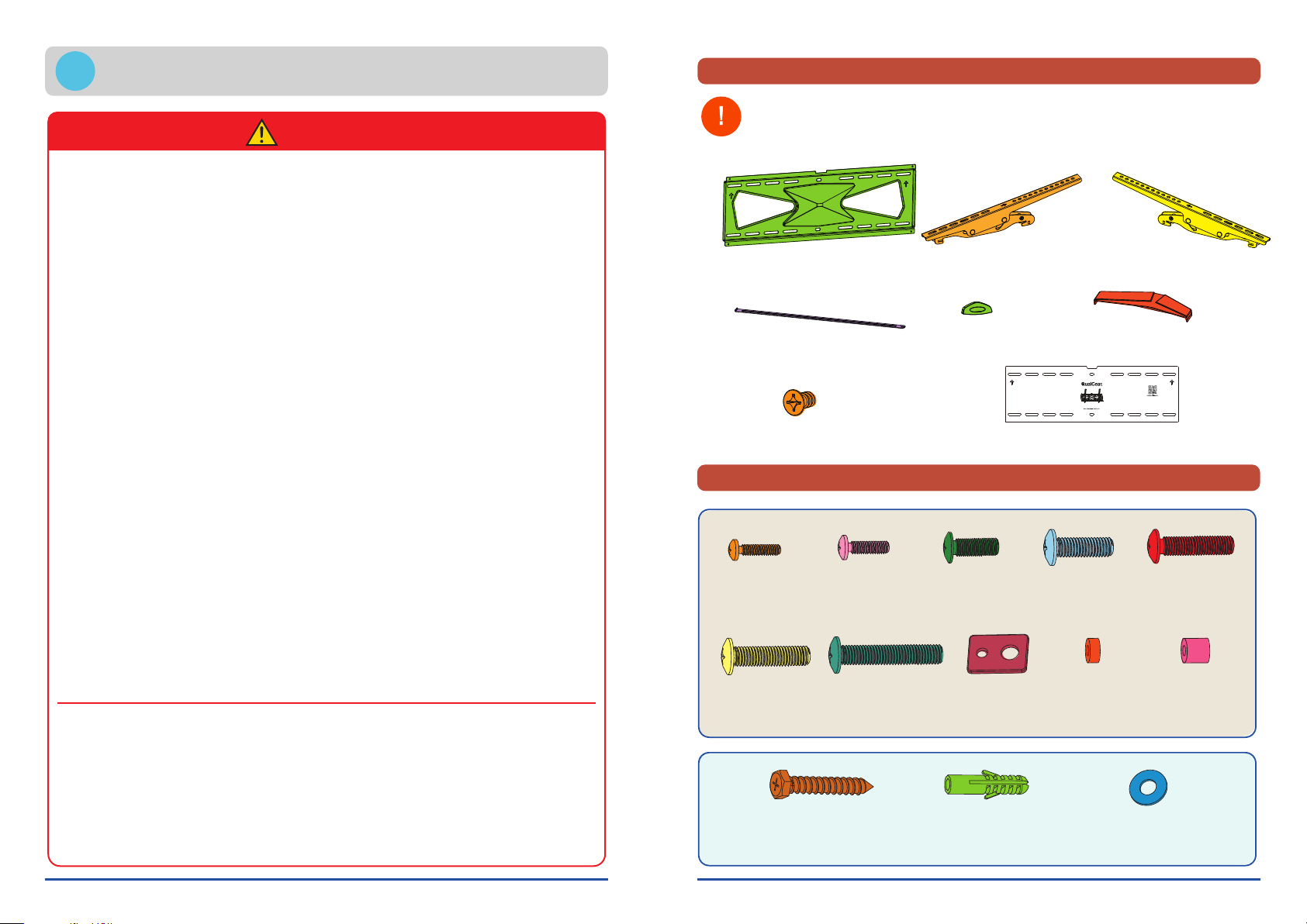
Parts Checklist
NOTE
WARNING
This product was designed to be installed on the following wall construction only:
WALL CONSTRUCTION HARDWARE REQUIRED
Wooden Stud Included
Wooden Beam Included
Solid Concrete Included
Other Contact Qualified Professional
Hardware Package
IMPORTANT: Before starting installation, please check that all parts shown in this checklist
are included. If any parts are missing or damaged, contact your local distributor or
until you receive all the parts.
Do not begin to install your QualGear product
until you have read and understood all the
instructions and warnings contained in this
installation manual. If you have any questions
regarding the instructions, for US customers
please contact QualGear customer support
via email at support@qualgear.com. For
all international customers, please contact
your local distributor.
This product should only be installed by
someone of good mechanical aptitude, has
experience with basic building construction,
and fully understands these instructions.
This product was designed to be installed
and utilized only as specified in this manual.
Improper installation of this product may cause
damage or serious injury. QualGear is not
liable for the improper use or installation of its
products.
Make sure that the supporting surface
will safely support the combined load of the
equipment and all attached hardware and
components.
Always use an assistant or mechanical
lifting equipment to safely lift and position the
equipment.
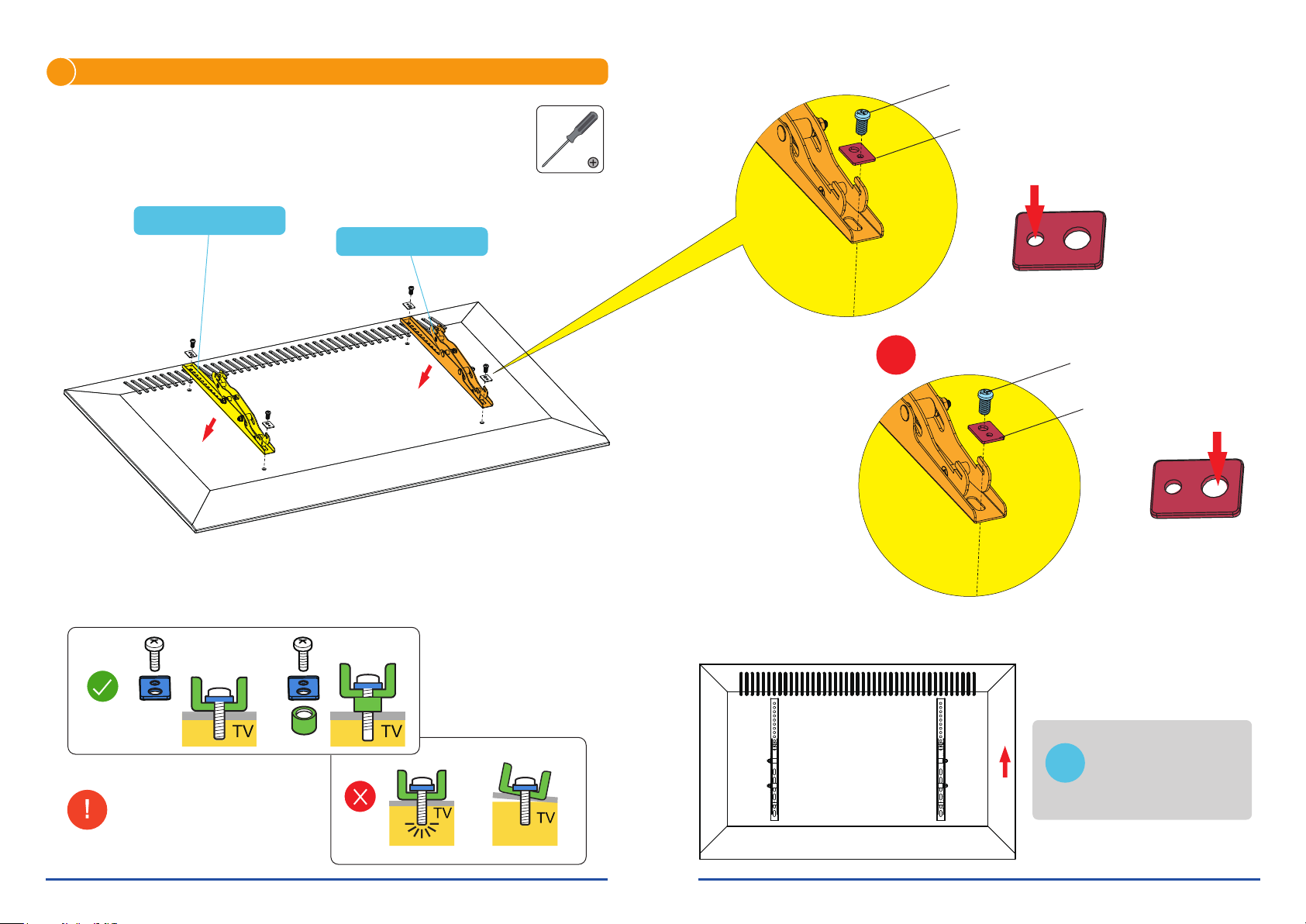
Tighten screws firmly, but do not over tighten.
Over tightening can damage the items, greatly
reducing their holding power.
ALL QUALGEAR products are intended for
indoor use only and any outdoor use voids the
limited warranty.
ALL QUALGEAR products are designed
and tested for residential use only and any
commercial use voids the limited warranty.
For warranty information, please visit
http://www.qualgear.com/warranty.php.
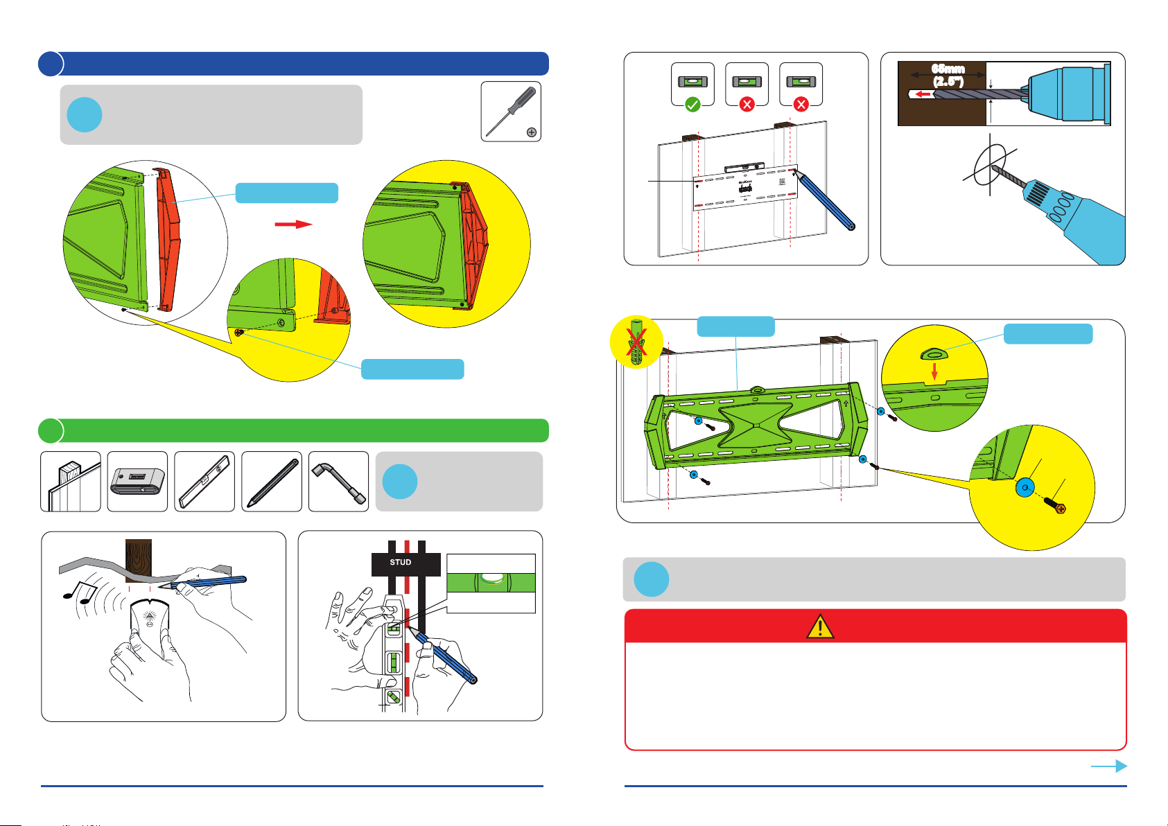
If mounting to wooden studs, make sure that
mounting screws are anchored into the center
of the studs. Use of an edge-to-edge stud finder
is highly recommended.
Never exceed the maximum rated weight
specified in this manual.
All bolts and screws must be used at the
designated points in the installation instructions
to prevent property damage and/or personal
injury.
DO NOT install near air conditioner vents or
where there is excessive dust or smoke.
When drilling holes in the wall, it is very
important to take care of electrical cables,
water, or gas pipes in the wall. 5.5mm/8.5mm
Washer (x4)
M-H
ST2.9x6.5 Screw (x4)
G
Marking Template (x1)
H
Wall Plate (x1)
A
Bubble Level (x1)
E
Safety Bar (x1)
B
Decorative Cover (x2)
F
Left Adapter Bracket (x1)
C
Right Adapter Bracket (x1)
D
QG-TM- 031- BLK
M4x14mm (x4)
M-A
M8x50mm (x4)
M-G
M5x14mm (x4)
M-B
M6x14mm (x4)
M-C
M8x20mm (x4)
M-D
5mm
Small Spacer (x8)
M-I
M6x30mm (x4)
M-E
15mm
Large Spacer (x8)
M-J
10x60mm
Concrete Anchor (x6)
W-B
D6 Washer (x6)
W-C
Lag Bolt
ST6.3x65mm
(x6)
W-A
M8x30mm (x4)
M-F