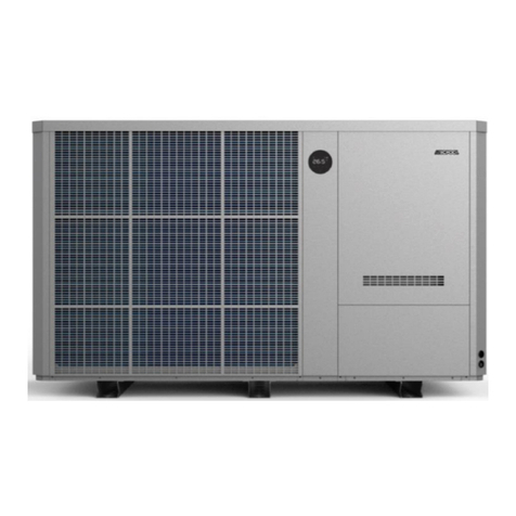
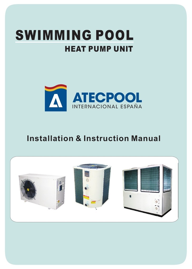
atecpool SIROCCO AVHP265 User manual

ATECPOOL SIROCCO HEAT PUMP > User Manual
SIROCCO
INVERTER HEAT PUMP
Models: AVHP265 & AVHP308 & AVHP352& AVHP411
FULL DC INVERTER SWIMMING POOL HEAT PUMP
USER MANUAL
Please read this manual carefully before using and keep it in a safe place.

ATECPOOL SIROCCO HEAT PUMP > User Manual

ATECPOOL SIROCCO HEAT PUMP > User Manual
Contents
I. Unit Parameters .................................................................................................................. 1
1. Appearance ....................................................................................................................... 1
II. System Specification ......................................................................................................... 2
1. Specification ................................................................................................................... 2
2. Unit Dimensions .............................................................................................................. 4
3. Exploded View ................................................................................................................ 5
III. Installation Instructions ..................................................................................................... 6
1. Pre-Requirements .............................................................................................................. 6
2. Location and pipe connection............................................................................................. 6
3. Installation Layout .............................................................................................................. 7
4. Electrical Connection ......................................................................................................... 8
4.1 Wiring: .......................................................................................................................... 8
IV. Running Test .................................................................................................................... 9
1. Inspection Before Running Test ...................................................................................... 9
2. Control Function Description ........................................................................................... 9
2.1 Operation Description ................................................................................................... 9
3. Fault Code and Solution ................................................................................................ 12
3.1. Fault Code Description .............................................................................................. 12
3.2. Troubleshooting ......................................................................................................... 14
V. WIFI Settings................................................................................................................... 15

ATECPOOL SIROCCO HEAT PUMP > User Manual

ATECPOOL SIROCCO HEAT PUMP > User Manual
1
I. Unit Parameters
1. Appearance
Please read the below instructions.
● Please install the unit in compliance with local laws, regulations and standards;
● Confirm power voltage and frequency;
● The unit should be installed by a professional installer
Warning
To be installed by professional installer only
⚠

ATECPOOL SIROCCO HEAT PUMP > User Manual
2
II. System Specification
1. Specification
Model AVHP265 AVHP308
Air Temperature: 27
℃
, inlet/outlet water temperature: 26
℃
/28
℃
, humidity 80%
Heating capacity (kW) 9.2-26.5 10.3-30.8
Power input (kW) 0.62-4.34 0.7-5.06
COP 14.82-6.1 14.7-6.09
Air Temperature: 15
℃
, inlet/outlet water temperature: 26
℃
,humidity 70%
Heating capacity (kW) 7.86-17.87 8.55-19.84
Power input (kW) 1.11-3.74 1.17-4.17
COP 7.05-4.78 7.28-4.76
Air Temperature: 35
℃
, inlet/outlet water temperature: 30
℃
/28
℃
Cooling capacity (kW) 7.5-10.25 8.8-11.9
Power input (kW) 1.41-2.53 1.77-2.94
EER (W/W) 5.32-4.05 4.95-4.05
Air Temperature: 43
℃
, inlet/outlet water temperature: 30
℃
/28
℃
Cooling capacity (kW) 4.5-8.23 4.7-9.56
Power input (kW) 1.01-2.56 1.05-2.97
EER (W/W) 4.45-3.21 4.48-3.21
Power supply (V/Ph/Hz) 380-415V/3N~/50-60Hz
Max power input (kW) 6.1 6.5
Max current (A) 10.9 11.6
Heating temperature range 27°C~34°C
Cooling temperature range 26°C~15°C
Running temperature range -10°C~48°C
Refrigerant R410A
Compressor MITSUBISHI ELECTRIC ( DC inverter)
Air side heat exchanger Hydrophilic fin and tube
Water side heat exchanger Titanium tube heat exchanger
Water flow (m
³
/h) 11.4 13.2
Net dimension LxWxH (mm) 760x679x965 795*742*965
Water pipe connection (mm) 50
Net weight (kg) 105 108
Noise level dB(A) 61 62
Water proof level IPX4

ATECPOOL SIROCCO HEAT PUMP > User Manual
3
Model AVHP352 AVHP411
Air Temperature: 27
℃
, inlet/outlet water temperature: 26
℃
/28
℃
, humidity 80%
Heating capacity (kW) 11.7-35.2 12.9-41.1
Power input (kW) 0.79-5.77 0.88-6.95
COP 14.82-6.1 14.74-5.91
Air Temperature: 15
℃
, inlet/outlet water temperature: 26
℃
/28
℃
,humidity 70%
Heating capacity (kW) 8.96-24.56 9.51-28.1
Power input (kW) 1.31-5.25 1.36-5.98
COP 6.84-4.68 7-4.7
Air Temperature: 35
℃
, inlet/outlet water temperature: 30
℃
/28
℃
Cooling capacity (kW) 5.56-14.24 5.98-17.14
Power input (kW) 1.11-3.58 1.19-4.27
EER (kW) 5.01-3.98 5.03-4.01
Air Temperature: 43
℃
, inlet/outlet water temperature: 30
℃
/28
℃
Cooling capacity (kW) 5.06~11.4 5.28~13.71
Power input (kW) 1.15~3.51 1.19~4.18
EER (W/W) 4.4~3.25 4.44~3.28
Power supply (V/Ph/Hz) 380-415V/3N~/50/60Hz
Max power input (kW) 7.3 8.0
Max current (A) 13.0 14.3
Heating temperature range 27°C~34°C
Cooling temperature range 26°C~15°C
Running temperature range -10°C~48°C
Refrigerant R410A
Compressor MITSUBISHI ELECTRIC ( DC inverter)
Air side heat exchanger Hydrophilic fin and tube
Water side heat exchanger Titanium tube heat exchanger
Water flow (m
³
/h) 15.1 17.6
Net dimension LxWxH (mm) 900x812x1054
Water pipe connection (mm) 50
Net weight (kg) 137 140
Noise level dB(A) 67 68
Water proof level IPX4
The technical specification of our heat pumps is provided for information purpose only. We reserve
the right to make change without notice in advance.
1. Ambient air temperature
2. Initial water temperature
3. Noise at 1m, 4m and 10m comply with Directives EN ISO 3741 and EN ISO 354
4. Calculate according to an in-ground private swimming pool covered with bubble

ATECPOOL SIROCCO HEAT PUMP > User Manual
4
2. Unit Dimensions
Model A B C D E F G H I
AVHP265 760 679 965 725 715 375 192 155 268
AVHP308 795 742 965 760 738 430 247 155 268
AVHP352 900 812 1054 865 846 500 252 155 268
AVHP411

ATECPOOL SIROCCO HEAT PUMP > User Manual
5
3. Exploded View
1
Fan protection cover 10
Electrical box 3 19
Front panel 1
2
Fan 11
Stand column 2 20
Controller
3
Fan motor 12
Metal mesh cover 2 21
Front panel 2
4
Top cover plate 13
Fin heat exchanger 22
Fixed plate
5
Metal mesh cover 14
Four way valve welding assembly
23
Globe valve
6
Stand column 1 15
Titanium tube heat exchanger 24
Drive board
7
Damper 16
Gas liquid separator 25
Filter welding components
8
Electrical box 1 17
Inverter compressor 26
Chassis components
9
Electrical box 2 18
Stand column 3 27
Inlet piping components

ATECPOOL SIROCCO HEAT PUMP > User Manual
6
III. Installation Instructions
WARNING: Only a professional is allowed to install the heat pump. Unqualified users cannot
install by themselves, otherwise the heat pump might be damaged and the user's safety
will be risked.This section is provided for information purposes only and must be checked
and adapted if necessary, according to actual installation conditions.
1. Pre-Requirements
Equipment needed for installation of heat pump:
● Suitable power supply cable for unit’s power.
● A by-pass kit and an assembly of PVC tube, stripper, PVC adhesive and sandpaper.
● A set of wall plugs and an expansion screw.
● We recommend using a flexible PVC pipe in order to reduce transmission of vibration.
● Suitable fastening studs may be used to raise the unit.
2. Location and pipe connection
IMPORTANT: The inverter pool heat pump should be installed in a good ventilation place.
1) The frame must be fixed by bolts (M10) to a concrete base or brackets. The
concrete base must be solid and fastened; the bracket must be strong enough and
antirust treated;
2) Please don’t stack substances that will block air flow near inlet or outlet area, make sure
there is no barrier within 50cm behind the main machine, or the efficiency of the heater will
be reduced or the machine may break;
3) The machine needs an appended pump (not included with the heat pump).
For the recommended pump specification-flux: refer to Technical Parameter,
Max. Lift ≥10m;
4) When the machine is running, there will be condensation water discharged from the
bottom, please pay attention to it. Please hold the drainage nozzle (accessory) into the
hole and clip it well, and then connect a pipe to drain the condensation water out.
Do not place anything within at least 1m in front of the heat pump. Leave at least 50cm of empty space around the sides and
rear of the heat pump. Do not put anything on or in front of the heat pump!

ATECPOOL SIROCCO HEAT PUMP > User Manual
7
The inlet and outlet water unions can’t stand the weight of soft pipes. The heat pump
must be connected with hard pipes!
3. Installation Layout
The heat pump is connected to a filtration circuit with a by-pass valve. The by-pass valve
should be half-opened (throttled), while all the other valves should be completely opened. It
is suggested that the by-pass valve only be opened half way to avoid excessive pressure
on the heat pump.
It is imperative that the by-pass is placed after the water pump and filtration. The by-pass
path usually consists of 3 valves. That makes it possible to adjust water flow which passes
through the heat pump and isolates the heat pump completely from any maintenance
without affecting flow of filtration cycle. The filter must be cleaned regularly to ensure that
the water in the system is clean and avoids blocking the filter. It is necessary that the
drainage valve is fixed on the lower water pipe. If the unit is not running during winter time,
please disconnect the power supply and let water drain out from the unit through the
drainage valve. If the ambient temperature of the running unit is below 0℃, please keep
the water pump running.

ATECPOOL SIROCCO HEAT PUMP > User Manual
8
4. Electrical Connection
Power Supply Wires Size
Model Power Supply Wires
Electricity Supply Cable Diameter Specification
AVHP265
380-415V/3Ph/50Hz 5×2.5mm
²
AWG 12
AVHP308
380-415V/3Ph/50Hz 5×2.5mm
²
AWG 12
AVHP352
380-415V/3Ph/50Hz 5×4.0mm
²
AWG 10
AVHP411
380-415V/3Ph/50Hz 5×4.0mm
²
AWG 10
WARNING: Power supply of heat pump must be disconnected before any operation.
Please comply with the following instruction to connect the heat pump.
Step 1: Detach electrical side panel by a screwdriver to access the electrical
terminal block.
Step 2: Insert cable into heat pump unit port.
Step 3: Connect power supply cable to terminal block according to the diagram below.
4.1 Wiring:
a. Connect to appropriate power supply; the voltage should comply with the rated
voltage of the products.
b. Earth the machine well.
c. Wiring must be handled by a professional technician according to the circuit diagram.
d. Set leakage protector according to the local code for wiring (leakage operating current ≤
30mA).
e. The layout of power cable and signal cable should be orderly and not affecting each other.
⚠

ATECPOOL SIROCCO HEAT PUMP > User Manual
9
IV. Running Test
1. Inspection Before Running Test
a. Please run an inspection test after completing installation;
b. Before running test, confirm below items and write √ in the block;
● Unit installed correctly □
● Power supply voltage is the same as unit rated voltage □
● Correct piping and wiring □
● Air inlet and outlet ports from the air unit unblocked □
● Drainage and venting are unblocked and no water leaking □
● Leakage protector is working □
● Piping insulation is working □
● Ground wire is connected correctly □
c. All wiring and piping should be connected well and carefully checked, then fill the water
tank with water before power is switched on;
d. Empty all air within pipes and from water tank, then press “on-off” button on control
panel to run the unit at setting temperature;
e. Items need to be checked during running test:
● During the first running, check if unit current is normal or not;
● Check if each function button on control panel are functioning correctly or not;
● Display screen is correct or not;
● Is there any leakage in the whole heating circulation system?
● Condensation drain is correct or not;
● Are there any abnormal sounds or vibration while running the unit?
2. Control Function Description
2.1 Operation Description
①Control Panel Diagram

ATECPOOL SIROCCO HEAT PUMP > User Manual
10
②Panel Symbol Description
③Operation Guideline List
NO.
Item
Operation Way
1 Unlock Press the " " and " " keys for 3 seconds in the main interface to
unlock /lock the screen.
2 On-off In the main interface, press and hold the " " key for 3 seconds to turn
on / off
.
3 Check Running
Parameters
In the main interface, press and hold the " " key for 3 seconds to
enter the unit status parameter query, cooperate with the " " and "
" keys for parameter browsing, and press the " " key to exit the
parameter query.(See table 1)
Symbol
Name
Symbol
Name
Symbol
Name
On-off
Heating Mode
or
Defrosting
Silent Mode
Set Cooling Mode Smart Mode
Up
Key lock
Powerful Mode
Down
Fault
Mode
Wi-Fi

ATECPOOL SIROCCO HEAT PUMP > User Manual
11
NO.
Item Operation Way
4 Choose Mode In the power on state, long press " " for 3 seconds to switch the
working
mode: heating mode and cooling mode.
5 Mode Switch
In the power on interface, press " " to switch frequency mode: mute,
smart and strong mode.
6 Adjust Temperature In the power on interface, press " " or " " to adjust the current
mode setting temperature.
7 Adjust Time
Long press " " and " " for 3 seconds to enter the clock setting
state. First, the hour flashes, indicating that the hour value of the current
time can be adjusted through " " and " " keys. Every time you
press the " " key for plus one hour, every time you press the " "
key for minus one hour. If you hold down the " " key or " " key, the
hours will be incremented or decremented automatically. After setting
the hour value, press " " again; At this time, the minute flashes,
indicating that the minute value of the current time can be adjusted
through the " " and " "key. After setting the minute value, press "
" again to finish.
8 Adjust Timing
Press " " for 3 seconds to enter the timing setting:
Enter timing selection,the hour of "Timing On 1" will flash ,collect " "
and " "can set hour; Click " " again to switch to the minute of
"Timing On 1" ,collect " " and " " can set minute;
Click " " again to set "Timing Off 1" in the same way.
Other time period setting in turn and so on;
Press" "can Exit and Enter;
Back to main interface, it will show the number of scheduled time
periods;
Cancel timing setting:
When the “Timing On” and “Timing Off” are the same, the timer setting
of the current time period is canceled.
9 Forced Defrosting Press the " "and " " keys to enter the forced defrost mode.
When
entering the defrost, showing flashes"
".
10 Celsius/Fahrenheit
switch When off ,Press " "and" " for 3 seconds in main interface to switch
Celsius/Fahrenheit
11 Turn on Electric
Heater Manually Long press " " for 3 seconds in main interface to turn on/off the
electric heater function.

ATECPOOL SIROCCO HEAT PUMP > User Manual
12
Table 1
Code Meanings
A01 Water inlet temperature
A02 Water outlet temperature
A03 Ambient temperature
A04 Exhaust temperature
A05 Air inlet temperature
A06 Outer coil temperature
A07 Inner coil temperature
A08 Main EEV opening
A09 Reserved
A10 Compressor current
A11 IPM temperature
A12 DC bus voltage value
A13 Actual speed of compressor
A14 DC fan speed
3. Fault Code and Solution
3.1. Fault Code Description
1) In the running process of unit, the unit may be faulted if the following code is displayed, please
turn off power switch of the unit and turn on power switch of unit again after 30 seconds. The
code is no longer displayed, that means the unit could be used again. If the code is displayed
again, please contact our company for troubleshooting!
Code Description Reservations
Er 03 Water flow protection Check water flow switch, change the switch
if necessary
Er 04 Winter anti-freezing Water pump will run automatically for first
grade antifreeze
Er 05 High pressure Protection
Measure the pressure value when heat
pump is heating(cooling), if it’s higher than
44.0 bar, it means heat pump has got really
higher pressure protection:
1. Detect EEV step, low pressure and
suction temp;
2. Detect the inlet/outlet water temp,;
3. Maybe there is some air in the
refrigeration system;
4.Clean the water exchanger or water filter
Er 09 Communication failure between Display and
PCB
1.Check if the communication connection
wire between display and PCB is well .
Change or mend the wire if necessary .
Check the PCB or display. If damaged,
Change the corresponding part .

ATECPOOL SIROCCO HEAT PUMP > User Manual
13
Er 10
Communication failure of frequency conversion
module(alarm when communication between
display and PCB is disconnected)
Change PCB.
Er 12 High exhaust temp protection
1.Replace the compressor exhaust
temperature sensor.
2.Reconnect or clean compressor exhaust
temperature sensor and wrap it with
insulation tape.
3.Replace the controller or PC Board.
Er 15 Water inlet temperature failure Check the connection, change the sensor if
necessary.
Er 16 External coil temperature failure Check the connection, change the sensor if
necessary.
Er 18 Exhaust temperature failure Check the connection, change the sensor if
necessary.
Er 19 DC fan motor failure
1.Check DC fan motor. Change it if
damaged.
Check output port of DC fan motor on PCB.
Change the PCB if there is no output.
Er 20 Abnormal protection of frequency conversion
module
Solve it according to the subsidiary error
codes in the following table.
Er 21 Ambient temperature failure Check the connection, change the sensor if
necessary.
Er 23 Low outlet water temp protection when cooling Check the water flow and water
system,mend it if necessary.
Er 27 Water outlet temperature failure Check the connection, change the sensor if
necessary.
Er 28 CT over current protection
Er 29 Suction temperature failure Check the connection, change the sensor if
necessary.
Er 32 High outlet water temperature protection when
heating
Check the water flow and water
system,mend it if necessary
Er 33 Outdoor coil high temperature protection Wait for the ambient temperature drops and
restart the unit.
Er 42 Internal coil temperature failure
E20 fault will display the following error codes at the same time, the error codes will switch every
3 seconds. Among them, error codes 1-128 appear in priority. When error codes 1-128 don’t
appear, then it will show error codes 257-384 . If two or more error codes appear at the same
time, then display error codes accumulation. For example, 16 and 32 occur at the same time, it
will show 48.
Code
Parameters Meaning Description Fault Solution
1 IPM over current IPM module issues Replace the inverter
module
2 Abnormal press
synchronization Compressor failure Replace the compressor
4 Reservation -- --

ATECPOOL SIROCCO HEAT PUMP > User Manual
14
8 Compressor output phase
loss
Compressor connection broken, bad
contact Check compressor circuit
16 DC bus voltage is low Input voltage is too low, pfc module
fault
Check input
voltage,replace module
32 DC bus voltage is high Input voltage is too high, pfc module
fault
Replace the inverter
module
64 Imp temp. Is too high Fan failure, air duct blockage Check fan and air duct
128 Imp temp. Fault Short circuit or open circuit fault of IPM
sensor
Replace the inverter
module
257 Communication failure The inverter module has not received
the command from the main controller
Check the
communication line
between main controller
and inverter module
258 AC input phase loss Input phase loss (available for three-
phase module) Check the input circuit
260 AC input over current Input three-phase unbalance(available
for three-phase module)
Check the three-phase
voltage
264 AC input voltage is low Input voltage is low Check the input voltage
272 High pressure failure Compressor high voltage failure
(Reservation)
288 IPM temp. Is too high Fan failure, air duct blockage Check fan and air duct
320 The peak current of the
compressor is too high
Compressor current is too large, the
driver and the compressor do not
match
Replace the inverter
module
384 PFC module temp. is too
high PFC module temp. Is too high Check the PFC module
3.2. Trouble Shooting
Phenomenon Cause Solution
Unit is not running
1. Power outage
2. Power switch is not connected
3. Power switch fuse is burned-out
4. Timing is not up
1. Please wait for power supply
recovery
2. Connect power
3. Replace fuse
4. Please wait or cancel timing
setting
Unit is not running
after starting up
1. Compressor protection time interval is not
up
2. Water temperature of the unit does not
reach starting up water temperature value
1. Please wait patiently for the
end of protection time
2. Normal phenomenon and
wait for water temperature to
reach
Unit is running
normally, but hot
water temperature
is low
1. Improper temperature setting
2. Large hot water consumption
3. Air inlet port or outlet port of outdoor
machine or indoor machine is blocked
1. Set up proper temperature
2. Wait for temperature of hot
water to rise
3. Clear tuyere obstruction
Unit is running
automatically
Reach timing to start up Please shutdown manually or
cancel timing if
needn’t start up

ATECPOOL SIROCCO HEAT PUMP > User Manual
15
V. WIFI Settings
Software Installation
Method 1: Search”Smart life” in your APP store ,install “ ”.Click “GET” to install.
Method 2: Scan the QR code below.
Click "Create a new user" link to
enter the registration method
interface
registration method interface
If you already have an account,
click directly to sign in

ATECPOOL SIROCCO HEAT PUMP > User Manual
16
When a user enters the registration page, please follow the page prompt to register
User Login:
Once the registration is successful, the software will jump to the login screen and enter the
correct "user name" and "password" to log in.
Mobile phone first needs to connect to the network via WIFI
Follow the prompts to
complete the registration
Enter the correct username
Enter the correct password
Click the login button to sign in
Select the correct
This manual suits for next models
3
Table of contents
Other atecpool Heat Pump manuals
Popular Heat Pump manuals by other brands

Daikin
Daikin EWAT016CZN-A1 Installation, maintenance and operation manual

Goodman
Goodman ACNF Use and care instructions

Bosch
Bosch CA Installation, operation and maintenance manual

Zodiac
Zodiac POWER PAC 1M Instructions for installation and use

Daikin
Daikin VRV RXYQ5P7W1B Technical data

Daikin
Daikin EPRA08EAV3 Installer's reference guide

Payne
Payne Heat Pump owner's manual

Robur
Robur K18 Simplygas Installation, use and maintenance manual

Daikin
Daikin Altherma 3 R W Installer's reference guide

Carrier
Carrier 50ZHK Owner's information manual

Lennox
Lennox HP27?024 Unit information

habitat et jardin
habitat et jardin Eco Series Installation and user manual