atecpool AQUA METER User manual

AQUA METER
USER MANUAL

Contents
1
1Contents
1Contents 1
Table of Figures 2
2Introduction 3
Explanation of Safety Warnings 3
User Competence 4
3Safety and Responsibility 5
General Safety Warnings 5
Hazards arising from non-compliance to
safety instructions 6
Safe operation 6
Personal protective equipment 6
Personnel competence 6
4Appropriate and Desired Use 7
Notes about product warranty 7
Product Software 7
Principles 7
Foreseeable wrong use 7
4.4.1 Wrong assembly 7
4.4.2 Wrong installation 7
Wrong electrical wiring 7
5Product Description 8
Product Data 8
General Specifications 8
Electrical Features 8
Scope of Delivery 8
6Technical Data 9
7Dimensions 10
8Mechanical Installation 11
Wall Assembly 11
Panel Assembly 11
Sensor Assembly for each model 12
8.3.1 For CON Models 12
8.3.2 For ORP Models 12
8.3.3 For pH Models 12
9Electrical Installation 13
Plug Electrical Connection 13
Fixed Electrical Connection 13
Device Schema 14
Electrode Selection 15
9.4.1 Heat Sensor 15
9.4.2 Analogue Output 15
9.4.3 Digital Inputs 15
10 Operation 16
General Operation 16
Adjusting Device Output Control Mode 16
Parameters 17
10.3.1 Changing Parameter Value 17
Parameter List 18
Calibration 20
10.5.1 Calibration of pH and ORP Devices 20
Output Control Modes 22
Analogue Output Modes 23
Password Use 23
11 Maintenance / Malfunction Cases 24
Maintenance 24
Malfunction Cases 24
11.2.1 Electrical Malfunctions 24
12 Warranty / Standards 25
Warranty 25
Standards 25

Contents
2
Table of Figures
Figure 1 Front Side Device Size ......................... 10
Figure 2 Device Side Size .................................. 10
Figure 3 Device Rear Size.................................. 10
Figure 4 Wall Assembly ..................................... 11
Figure 5 Panel Assembly ................................... 11
Figure 6 For Con Models.................................... 12
Figure 7 For ORP Models ................................... 12
Figure 8 For pH Models...................................... 12
Figure 9 Plug Electrical Connection.................... 13
Figure 10 Fixed Electrical Connection ................ 13
Figure 11 Mainboard ......................................... 14
Figure 12 Mainboard AC input ........................... 14
Figure 13 Mainboard DC input ........................... 14
Figure 14 Heat Sensor ....................................... 15
Figure 15 NTC connection.................................. 15
Figure 16 pt100 connection............................... 15
Figure 17 Analogue Output ................................ 15
Figure 18 Jumper settings ................................. 15
Figure 19 Digital Inputs...................................... 15
Figure 20 Panel Tag........................................... 16
Figure 21 Adjusting Device Output Control Mode 16
Figure 22 Changing Paramater Value................. 17
Figure 23 Access to the calibration menu .......... 20
Figure 24 Single Point Calibration ...................... 20
Figure 25 Double Point Calibration ..................... 21
Figure 26 Calibration of Conductivity Device ...... 21

Introduction
3
2Introduction
Please read following information carefully and
completely. This information shall ensure that you
benefit from operating instructions at optimum
level.
These instructions define the functions of
technical data.
Explanation of Safety Warnings
These operating instructions give information
about the technical data and functions of the
product. And provide detailed safety information.
Safety warnings and notes are categorized as
below. Pictographs are used here as adapted for
different circumstances. These pictographs are only
for example.
DANGER!
Type and source of danger
Result: Death or severe injury.
Measures to be taken to prevent such danger.
Defines the danger that creates the threat
directly. Causes death or severe injury unless
prevented.
WARNING!
Type and source of danger
Possible Result: Death or severe injury.
Measures to be taken to prevent such danger.
Defines a possible dangerous situation. Causes
death or severe injury unless prevented.
CAUTION!
Type and source of danger
Possible Result: Light or insignificant
injuries. Material damage.
Measures to be taken to prevent such danger.
Defines a possible dangerous situation. Causes
light or insignificant injury unless prevented. Can
also be used for material damage warning.
NOTE!
Type and source of danger
Result: Causing damage to the product or
individuals.
Measures to be taken to prevent such danger.
Defines a possible damaging action. Causes
damage to the product or individuals unless
prevented.
INFORMATION!
Operational tips and additional information
Source of information. Additional measures.
Defines operational tips and other useful
information. Not given for a dangerous or
harmful situation.

Introduction
4
User Competence
WARNING!
Danger of injury in case of personnel incompetence!
Operator of device/facility is responsible for complying with competencies.
Incompetent personnel working with the device or keeping the device in danger zone might cause severe
injuries or material losses.
- All operations should be handled by competent personnel
- Keep away incompetent personnel from danger zones
Training
Description
Informed Person
Defines a person that has been informed about possible hazards in
case of unruly behaviors contrary to duties assigned, and informed
about relevant situations and informed about necessary protection
equipment and measures.
Trained User
Defines a person that meets the standards of an informed person and
plus trained by the manufacturer or another authorized sales partner
Trained Expert
Defines a person that can recognize possible hazards and evaluate the
duties assigned thanks to his/her knowledge of rules in addition to the
training, information and experience in that field. The activities based
on years of experience in that field can be taken into consideration
while assessing someone as an expert.
Electricity Expert
Defines a person that can work in electrical facilities, and recognize
and prevent possible dangers thanks to his/her knowledge of
regulations and standards in place in addition to the training,
information and experience.
Electricity experts should have received training on the field of work
and have knowledge on important standards and regulations.
Electricity expert should fulfill the provisions of legal regulations for
preventing accidents.
Customer Services
The service technicians that are trained and authorized for operations
in the facility by the manufacturer are described as customer services.

Safety and Responsibility
5
3Safety and Responsibility
General Safety Warnings
Following warnings are given for assisting you to
eliminate possible dangers that might arise while
using the product. Risk prevention measures are
always valid independent of any special action.
Safety instructions that give warning against certain
activities or situations are given in relevant sub-
sections.
DANGER
Life-threatening danger due to electric shock
Falsely wired, exposed or damaged cables might
injure you.
Replace damaged cables immediately.
Do not use extension cables.
Do not bury cables.
Fix cables to prevent damage to other
equipment.
DANGER
Do not use the product in explosive
environments.
WARNING
Causing damage to the product or individuals.
There is no on/off switch on the device
Device starts operating when powered after
connection to mains voltage.
Make sure that all screws are tightened and
sealed properly.
WARNING
Usage Error!
Possible Result: Death or severe injury.
Make sure that device is used only by
sufficiently qualified and competent personnel.
Operator is responsible for the competence
of personnel.
WARNING
Electronic Malfunctions!
Possible Result: Material damage that might
cause device to be damaged.
Device's electricity mains line shouldn't be set
up on installation with damaged data line.
Operator is responsible for taking appropriate
malfunction elimination measures.
CAUTION
Increased accident risk due to lack of
qualification on personnel side!
Product and accessories can only be mounted,
operated and maintained by staff with sufficient
qualifications.
Make sure that all actions are taken by personnel
with sufficient and appropriate qualifications.
Prevent access to system by unauthorized
persons.
CAUTION
Purpose Oriented Usage
Causing damage to the product or individuals.
Device has been designed to measure and
check liquids fluids.
This device can only be used in line with this
operating manual and technical data in operating
manuals and specifications of individual
components (such as Sensors, Dosing Pumps,
Calibration Tools, etc.)
CAUTION
Hassle-free Sensor Operation
Causing damage to the product or individuals.
Accurate measurement or dosing is only
possible with perfect sensors.
Pay attention to operating manuals of sensors.
Check and calibrate sensors regularly.

Safety and Responsibility
6
Hazards arising from non-
compliance to safety instructions
Non-compliance with safety instructions will bring
risks not only for the staff but also for environment
and the unit.
Here are some specific consequences:
Failure of vital functions in product and system.
Failure of necessary maintenance and repair
methods.
Safe operation
There are more safety rules in addition to the safety
instructions stated in this operating manual and
they should be followed:
Accident prevention regulations safety and
operating provisions
Safety measures for using dangerous items
Environmental protection provisions,
Applicable standards and legislation.
Personal protective equipment
You should use relevant protective equipment
depending on the type of work and degree of risk.
As minimum, following protective equipment is
provided:
Protective Protective Protective
Clothing Gloves Goggles
The operator should use protective equipment
during these tasks:
Assigning,
When device is working,
Demounting, maintenance works, disposal.
Personnel competence
Any staff member working on the device should
have specific knowledge and skills.
Anyone working on the device should meet
following conditions:
- Participation in all training courses,
- Personal fitness to the specific task,
- Personal competence for the specific task,
- Training for the use of device,
- Safety equipment data and mode of operation
- This Operating Manual and especially the safety
instructions relevant to this work with sub-sections,
- Knowledge on basic arrangements relevant to
health, safety and accident-prevention.
All persons should have following qualifications as
minimum:
-Receive training as expert to work on the product
independently,
-Receive sufficient training to work on the product
under the guidance and surveillance of a trained
expert,
This Operating Manual differentiates user groups:
(see 2.2 User Competence Page 4)

Appropriate and Desired Use
7
4Appropriate and Desired Use
Notes about product warranty
Undefined use of the product in any way might risk
the function or desired protection of the product.
This shall invalidate warranty claims!
Please remember that responsibility lies with the
user in following cases:
•Use of the product in an inconsistent way with
the section titled "appropriate and desired
use" especially with regards to safety
•Unauthorized changes on the device by the user
Product Software
Aquameter v3 R4
Principles
•Information on usage and environment (see 6
Technical Data Page 9).
•Product is not designed for outdoors unless
appropriate protective measures are taken.
•Avoid liquid and dust leakage into product and
also direct sunlight exposure.
•Do not operate the product in a potentially
explosive environment unless there is EC
Certificate of Conformity for potentially
explosive atmospheres.
Foreseeable wrong use
You can find below information about unaccepted
product practices or relevant equipment practices.
This section has been designed to detect and
prevent possible wrong uses beforehand.
Foreseeable wrong use will affect product life:
4.4.1Wrong assembly
Wrong or loose screwing.
4.4.2Wrong installation
Wrong connection of sensors due to wrong material
or improper connections.
Damage in cable lines due to twisting or excessive
tightening.
Use of damaged parts,
Wrong electrical wiring
Unsafe mains or mains voltage that do not comply
to standards.
Wrong connection cables for mains voltage.
Installation where it is not possible to cut off power
supply immediately or easily.

Product Description
8
5 Product Description
Product Data
AQUA METER is a Measurement Conversion
and Control device that has been developed to
measure three various values as pH, ORP and
Conductivity and to convert them into and control
various output units.
Described as AQUA METER pH, AQUA METER
ORP or AQUA METER CON, each of these devices is
related to only one unit. pH and CON devices also
fulfill heat compensation of units by measuring
heat at the same time.
General Specifications
This operating manual is applicable to Aquameter
Control device. Installation, operation and service of
all these control devices are different from each
other (certain differences in technical data,
malfunctions and repair).
Standard Hardware
•measurement, control and conversion
device for pH, ORP, conductivity.
•pH, ORP measurement with standard
combined electrodes; conductivity
measurement with standard
conductivity probe.
•Heat compensation in measurements
with heat measurement feature.
•Fully digital adjustment and automatic
calibration without adjustment bar,
screw driver, etc. thanks to buffer
liquids.
•Chemical Level Tracking
•Storage Level / Flow Tracking
•Ratio Control per Signal Input
•High operational reliability, electrical
isolation, full insulation against
humidity, acid and chlorine steam.
•Easy and flexible installation.
•Micro controller technology.
•Analogue control output (0-5V, 0-10V,
1-5V, 0-10mA, 0-20mA, 4-20mA, )
•Programmable alarm output.
•User Password
•Heat Sensor
Electrical Features
Device fulfills control duty by respecting user
settings.
Device complies with electrical devices regulations.
Device complies with following standards:
TS EN 61010-1
TS EN 61326-1
Scope of Delivery
Control device
User's Manual
Assembly Set
Calibration Liquid
CAUTION
Calibration liquid varies based on the model type
of your device.

Technical Data
9
6 Technical Data
Model
pH
ORP
Conductivity
Measurement Range
pH 0,00 –14,00
0 –50ºC NTC
-25 –+125ºC Pt100
0 –1250mV
0,01 –20,00mS
0 –50ºC NTC
-25 –+125º Pt100
Solubility
0,01 pH, 0,1 ºC
1 mV
0,01 mS 0,1 ºC
Heat Compensation
NTC - Pt100
NTC - Pt100
Relay
Control Output
NO; 220VAC 5A, NC; 250VAC 2A
NO; 28VDC 5A, NC; 28VDC 1A
Relay
Alarm Output
Analogue Output
0-5V, 0-10V, 1-5V, 0-10mA, 0-20mA, 4-20mA
Chemical Level Input
NO-NC
Storage Level / Flow Input
NO-NC
Signal Input
0Hz –1KHz
Feeding
230VAC 50-60 Hz, 6W 12-28VDC (for DC model), 6W
Fuse
AC model : 63mA Fast 20x5mm glass fuse
DC model : 1A Fast 20x5mm glass fuse
Operating Temperature
0 .. 50 ºC
Body
IP56
Packaged Weight
1,17 Kg
Product Weight
0,7 Kg
Packaging Dimensions
210 x 240 x 180 mm
Product Dimensions
143 x 80 x 183 mm

Dimensions
10
7 Dimensions
Please find dimensions and assembly hole sizes of
the device below. All dimensions are given in mm.
Mark the surface on which the product is to be
installed in accordance with the template before
starting assembly.
Make sure that the surface is dry and clean.
Figure 1 Front Side Device Size
Figure 2 Device Side Size
Figure 3 Device Rear Size
Mechanical Installation
11
8 Mechanical Installation
Mechanical Assembly:See
User Competence page 4
CAUTION
Assembly Site and Conditions
▪Device meets IP65 protection and sealing if
all seals and screws are placed correctly.
▪Electrical assembly should be performed
after mechanical assembly.
▪Please choose a site that will lend easy
access to control panel.
▪Do not permit direct sunlight on the device.
▪Operating environmental temperature: -
20/+60°C and 90% relative humidity (non-
condensing)
▪Allowed working temperatures of other
sensors and actors should be considered.
▪This device has been designed only for
indoor use. Place it inside a panel to protect
from external factors for outdoor use.
CAUTION
Reading and Commanding Position
Install the device in a space with normal room
temperature that is well ventilated and place it at
eye level in order to read and manage it properly.
CAUTION
Assembly Position
Device has been designed to be used with wall-
type mount as a standard.
Assemble the device with the cable inlet facing
downwards all the time.
Allocate sufficient space for cables and hoses.
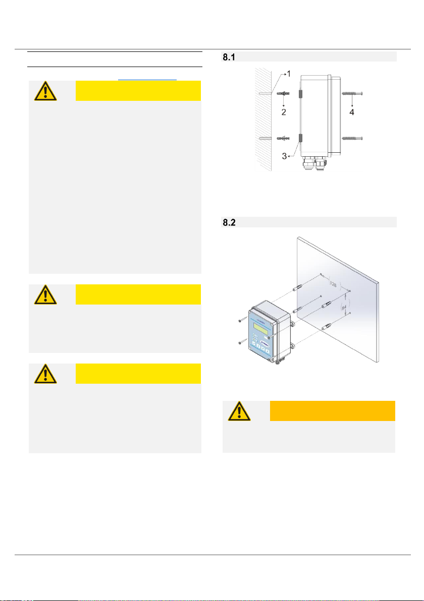
Wall Assembly
1) Ø 8x50mm 2) 8mm Anchor
3) Hanging Bracket 4) 4.2x50 YSB Screw
Panel Assembly
A: 128 mm B: 84 mm C: Ø 4,5 mm
WARNING
Place the control device by leaving 110 mm
space from four sides as minimum for the proper
position.
1. Mark the hole dimensions on the surface of
assembly.
2. Drill hole (1).
3. Place the anchor shown as (2) into the hole.
4. Align the hanging brackets (3) on the device to
the holes.
5. Screw and fix the device (4).
Figure 4 Wall Assembly
Figure 5 Panel Assembly

Mechanical Installation
12
Sensor Assembly for each model
8.3.1For CON Models
8.3.2For ORP Models
8.3.3For pH Models
Figure 6 For Con Models
Figure 7 For ORP Models
Figure 8 For pH Models
CONDUCTIVITY SENSOR INPUT
LEVEL SENSOR INPUT 1
LEVEL SENSOR INPUT 2
ORP SENSOR INPUT
LEVEL SENSOR INPUT 1
LEVEL SENSOR INPUT 2
TEMPERATURE SENSOR INPUT
pH SENSOR INPUT
LEVEL SENSOR INPUT 1
LEVEL SENSOR INPUT 2

Electrical Installation
13
9 Electrical Installation
Electrical Assembly: See
User Competence
page 4
WARNING
Parts Under Electric Voltage!
Possible Result: Death or severe injury.
Unplug from mains before opening the body.
Unplug damaged or broken devices from mains
to make them off-circuit.
WARNING
Humidity on Contact Sites
Protect electrical wire, cable and connection
socket from humidity using appropriate design
and technical measures. Humidity in contact
areas might cause damage
WARNING
Cable Duct
Cables should be driven inside a cable duct to
reduce tension.
Based on the model, device power supply can be
AC or DC. AC connection is shown next to here and
electrical properties are described in the technical
specifications. For DC connection, see 9.3 Device
Schema Page 14.
There are two relay outputs (for Control and
Alarm). Names of terminal connections inside the
device are given as abbreviations in front of the
connectors.
Electronic circuit is protected with fuse. Please use
appropriate fuse based on the model. See 6
Technical Data Page 9
Plug Electrical Connection
Fixed Electrical Connection
L: Phase N: Neutral E: Earthing (functional)*
•A switch or circuit breaker should be
integrated.
•Switch or circuit breaker should be placed
appropriately and easily accessible.
•Switch or circuit breaker should be marked
as separating element.
* WARNING
Functional earthing connection is used for
external devices. It is not a circuit protector.
Figure 9 Plug Electrical Connection
Figure 10 Fixed Electrical Connection
DEVICE
DEVICE
Circuit
Breaker
Switch

Electrical Installation
14
Device Schema
Jumper settings
Figure 11 Mainboard
Figure 13 Mainboard AC input
Figure 12 Mainboard DC input

Electrical Installation
15
Electrode Selection
Electrodes used by the device are shown on
the table. Connections are made with BNC
connector. It is stated on the device which
electrode to be connected where.
Device Type
Electrode Type
pH
Standard Combined pH Electrode
ORP
Standard Combined ORP
Electrode
Con
Conductivity Electrode
9.4.1 Heat Sensor
AQUA METER pH and
Con devices support
two types of heat
sensors as NTC and
Pt100. heat sensors
are capable of
connecting to connection point on the device
directly.
Detailed image of NTC
Connection point is
given on the left.
Pt100
Heat Sensor
Connection
9.4.2 Analogue Output
Device can give 6 different analogue
outputs in total. You can select one
of those outputs using the jumpers
on the device.
Analogue Output
Connection and Jumper
Settings
9.4.3Digital Inputs
There are 3 digital inputs as two level sensors and
one counter input while connections can be made
as seen on top.
Figure 19 Digital Inputs
Figure 14 Heat Sensor
Figure 15 NTC connection
Figure 16 pt100 connection
Figure 17 Analogue Output
Figure 18 Jumper settings

Operation
16
10 Operation
General Operation
Control panel consists of 4 function buttons and 3
status LEDs. You can access and control
parameters using these 4 function buttons.
Below you can find example of Set parameter.
Adjusting Device Output Control
Mode
Device output control mode is shown on right
upper corner of screen.
There are three different statuses.
OFF : Device output is constantly off.
AUTO : Device output starts automatically
based on the adjusted value.
ON : Device output is constantly on.
These can be changed using up button.
Figure 20 Panel Tag
Figure 21 Adjusting Device Output Control Mode

Operation
17
Parameters
10.3.1 Changing Parameter Value
Figure 22 Changing Paramater Value
Access parameters by pressing enter button.
See the screen on the left.
Use Up[ ] and down[ ] buttons to find Set parameter.
Screen on the Left
Enter the section to change parameter value by pressing enter button.
See the screen on the left.
Change the value as you desire using up and down buttons.
Exit after setting the value with enter button and return to previous menu.
[C] button will enable you to return to previous menu without setting the
value.
Use [C] button to return to main screen.

Operation
18
Parameter List
Parameter
Description
Value
Default
pH
ORP
Con
01
_Device
Settings from
Factory
Shows Device
Type
0: pH
1: ORP
3: Conductivity
0
1
2
02
_Temp.Sens.
Settings from
Factory
Shows
Temperature
Sensor Type
0: Pt100
1: NTC 10K
1
03
Mode
Device Operating
Mode
0: Off
1: Auto
2: On
0
04
Cont Mode
Device Control
Mode
0: Relay Control
1: Ratio Control
2: Signal Ratio Control
0
05
Output Mode
Output Mode
0: Increase Control
1: Decrease Control
2: Decrease / Increase Control
1
0
1
06
Cont. Run
Continuously
Operating
When device is On
mode
0: Return to Auto Mode in 1 minute
1: Continuous Output
0
07
Analogue
Type
0: Ratio Control Output
1: Full Scale Output
0
08
Temp Comp.
Temperature
Compensation
0: Passive
1: Active
0
0
1
09
Log Interv.
Data Sending
Period
0-30 min.
3
10
Pass Enable
Password
Protection
0: Passive
1: Active
0
11
Cal Type
Calibration Type
0: Single Point
1: Double Point
1
0
0
12
LR
Output on Lower
Limit Value
Exceed
0: Passive
1: Active
0
13
HR
Output on Higher
Limit Value
Exceed
0: Passive
1: Active
0
14
Filter Delay
Filter Delay
0-99 sec.
0
15
Level1 C
Type
Level 1 Input
Contact Type
0: NO
1: NC
0
16
LV2/FL Type
Level 2 Input /
Flow Switch
Contact Type
0: NO
1: NC
0

Operation
19
17
Pulse Count
Signal Ratio
Control Pulse
Count
0 –250 pulse
10 pulse
18
RelayOnTime
Signal Ratio
Control Relay On
Time
0,0-25,0 min.
1,0 min.
pH
ORP
Con
19
Set
Set point
0,00-
14,00pH
0-
1250mV
0,00-
20,00mS
7,00pH
650mV
5,00mS
20
Set Ofset
Offset level
0,00-
1,00pH
0-
100mV
0,00-
1,00mS
0,05pH
5mV
0,05mS
21
Ratio Diff.
Difference of
analogue output
100% point from
Set Value
0,00-
14,00pH
0-
1250mV
0,00-
20,00mS
1,00pH
100mV
1,00mS
22
Low Alarm
Value low alarm
0,00-
14,00pH
0-
1250mV
0,00-
20,00mS
6,00pH
550mV
4,00mS
23
High Alarm
Value high alarm
0,00-
14,00pH
0-
1250mV
0,00-
20,00mS
8,00pH
750mV
6,00mS
24
Buf Sol 1
Buffer 1 Liquid (in
pH and ORP
devices)
0,00-
14,00pH
0-
1250mV
0,00-
20,00mS
4,00pH
225mV
1,41mS
25
Buf Sol 2
Buffer 2 Liquid (in
pH and ORP
devices)
0,00-
14,00pH
0-
1250mV
0,00-
20,00mS
7,00pH
475mV
2,77mS
26
Password
Password Set
0000 –9999
0000
** Varies depending on device type. Values are as follows.
pH=14,00 ORP=1250 Con=20,00
Table of contents
Popular Measuring Instrument manuals by other brands


Young
Young 86004 instructions

TSI Instruments
TSI Instruments ALNOR MicroManometer AXD 550 owner's manual

Wohler
Wohler BC 600 operating manual

Flomotion Systems
Flomotion Systems LT260 Operation and maintenance manual

REED
REED R6010 instruction manual

WATERS CORPORATION
WATERS CORPORATION TA Instruments DSC 2010 Operator's manual