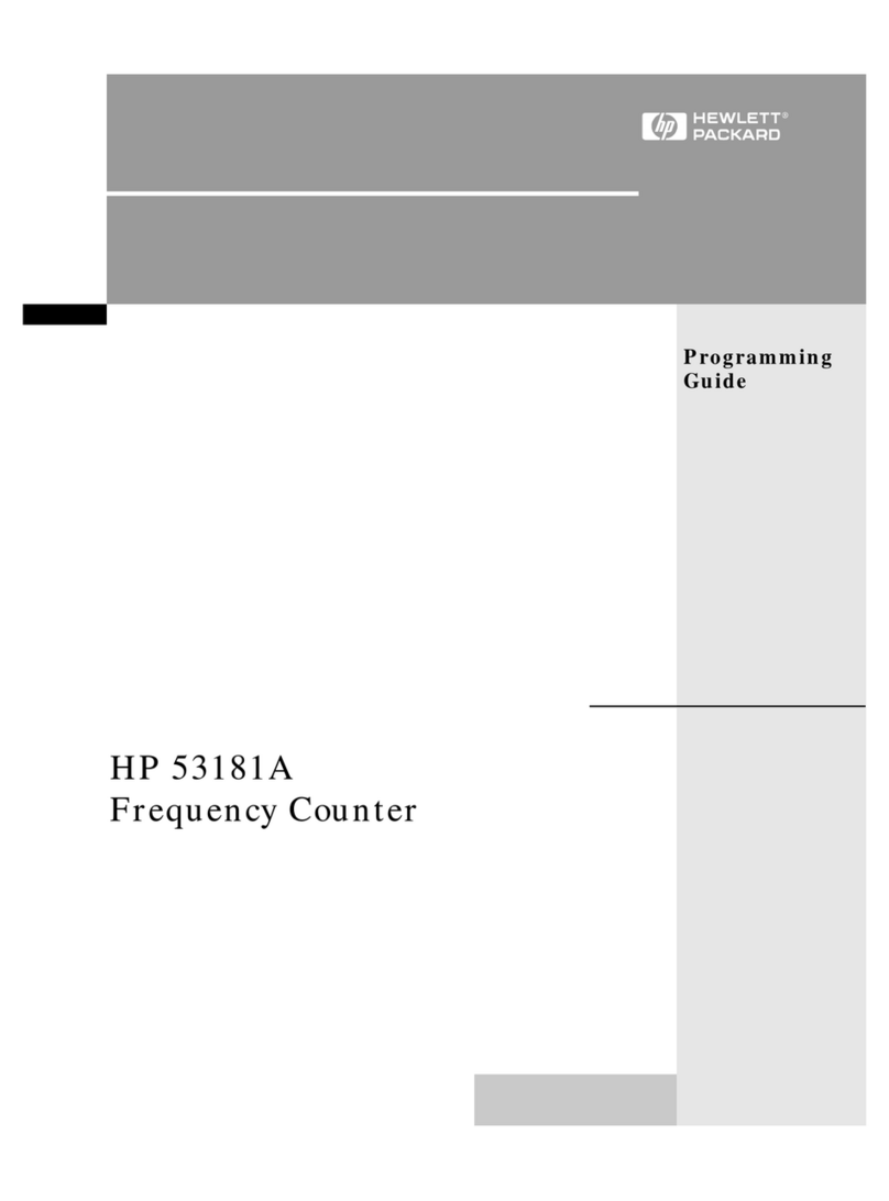
Agilent Technologies 53181A User manual

Agilent 53181A
225 MHz Frequency Counter
Operating Guide
Manual Part Number 53181-90001
Printed in Malaysia

NOTES

Agilent 53181A 225 MHz Frequency
Counter
Agilent 53181A
Operating Guide
This guide describes how to use the Agilent 53181A 225 MHz Frequency Counter.

Agilent Technologies, Inc. 7.NC.NL.A.11.03.97.R1.P.CW6FC
900 South Taft Avenue
Loveland, Colorado 80537 U.S.A.
Copyright 1994 - 2003
Agilent Technologies, Inc.
All Rights Reserved. Reproduction,
adaptation, or translations without
prior written permission is
prohibited, except as allowed under
the copyright laws.
Printed: November 2003
Printed in Malaysia
Manual part number
53181-90001
Certification
and Warranty
Certification
Agilent Technologies certifies that
this product met its published
specification at the time of shipment
from the factory. Agilent
Technologies further certifies that its
calibration measurements are
traceable to the United States
National Institute of Standards and
Technology (formerly National
Bureau of Standards), to the extent
allowed by the Institute’s calibration
facility, and to the calibration
facilities of other International
Standards Organization members.
Warranty
Agilent warrants Agilent hardware,
accessories and supplies against
defects in materials and
workmanship for a period of one year
from date of shipment. If Agilent
receivesnotice of such defects during
the warranty period, Agilent will, at
its option, either repair or replace
products which prove to be defective.
Replacement products may be either
new or like-new.
Agilent warrants that Agilent
software will not fail to execute its
programming instructions, for the
period specified above, due to
defects in material and workmanship
when properly installed and used. If
Agilent receives notice of such
defects during the warranty period,
Agilent will replace software media
which does not execute its
programming instructions due to
such defects.
Safety Considerations
General
This product and related
documentation must be reviewed for
familiarization with this safety
markings and instructions before
operation.
Before Cleaning
Disconnect the product from
operating power before cleaning.
Warning Symbols That May Be
Used In This Book
Instruction manual symbol; the
product will be marked with this
symbol when it is necessary for the
user to refer to the instruction
manual.
Indicates hazardous voltages.
Indicates earth (ground) terminal.
or
Indicates terminal is connected to
chassis when such connection is not
apparent.
Indicates Alternating current.
Indicates Direct current.
Safety Considerations (contd)
W
ARNING
BODILY INJURY OR DEATH
MAY RESULT FROM
FAILURE TO HEED A
WARNING. DO NOT
PROCEED BEYOND A
WARNING UNTIL THE
INDICATED CONDITIONS
ARE FULLY UNDERSTOOD
AND MET.
C
AUTION
Damage to equipment, or incorrect
measurement data, may result
from failure to heed a caution. Do
not proceed beyond a CAUTION
until the indicated conditions are
fully understood and met.
Safety Earth Ground
An uninterruptible safety earth
ground must be maintained from the
mains power source to the product’s
ground circuitry.
W
ARNING
WHEN MEASURING POWER
LINE SIGNALS, BE
EXTREMELY CAREFUL AND
ALWAYS USE A
STEP-DOWN ISOLATION
TRANSFORMER WHICH
OUTPUT IS COMPATIBLE
WITH THE INPUT
MEASUREMENT
CAPABILITIES OF THIS
PRODUCT. THIS PRODUCT’S
FRONT AND REAR PANELS
ARE TYPCIALLY AT EARTH
GROUND. THUS, NEVER TRY
TO MEASURE AC POWER
LINE SIGNALS WITHOUT AN
ISOLATION TRANSFORMER.

7.NL.A.11.03.97.R1.P.CW6BC
Warranty (contd)
Agilent does not warrant that the
operation of Agilent products will be
uninterrupted or error free. If Agilent
is unable, within a reasonable time,
to repair or replace any product to a
condition as warranted, customer
will be entitled to a refund of the
purchase price upon prompt return of
the product.
Agilent products may contain
remanufactured parts equivalent to
new in performance or may have
been subjected to incidental use.
The warranty period begins on the
date of delivery or on the date of
installation if installed by Agilent. If
customer schedules or delays Agilent
installation more than 30 days after
delivery, warranty begins on the 31st
day from delivery.
Warranty does not apply to defects
resulting from (a) improper or
inadequate maintenance or
calibration, (b) software, interfacing,
parts or supplies not supplied by
Agilent , (c) unauthorized
modificationormisuse, (d) operation
outside of the published
environmental specifications for the
product, or (e) improper site
preparation or maintenance.
TO THE EXTENT ALLOWED BY
LOCAL LAW, THE ABOVE
WARRANTIES ARE EXCLUSIVE
AND NO OTHER WARRANTY OR
CONDITION, WHETHER
WRITTEN OR ORAL, IS
EXPRESSED OR IMPLIED AND
AGILENT SPECIFICALLY
DISCLAIMS ANY IMPLIED
WARRANTIES OR CONDITIONS
OF MERCHANTABILITY,
SATISFACTORY QUALITY, AND
FITNESS FOR A PARTICULAR
PURPOSE.
Agilent will be liable for damage to
tangible property per incident up to
the greater of $300,000 or the actual
amount paid for the product that is
the subject of the claim, and for
damages for bodily injury or death,
to the extent that all such damages
are determined by a court of
competent jurisdiction to have been
directly caused by a defective
Agilent product.
TO THE EXTENT ALLOWED BY
LOCAL LAW, THE REMEDIES IN
THIS WARRANTY STATEMENT
ARE CUSTOMER’S SOLE AND
EXCLUSIVE REMEDIES.
EXCEPT AS INDICATED ABOVE,
IN NO EVENT WILLAGILENT OR
ITS SUPPLIERS BELIABLEFOR
LOSS OF DATA OR FOR DIRECT,
SPECIAL, INCIDENTAL,
CONSEQUENTIAL (INCLUDING
LOST PROFIT OR DATA), OR
OTHER DAMAGE, WHETHER
BASED IN CONTRACT, TORT, OR
OTHERWISE.
For consumer transactions in
Australia and New Zealand: the
warranty terms contained in this
statement, except to the extent
lawfully permitted, do not exclude,
restrict or modify and are in addition
to the mandatory statutory rights
applicable to the sale of this product
to you.
Assistance
Product maintenance agreements and
othercustomerassistanceagreements
are available for Agilent Technolo-
gies products.
For any assistance, contact your
nearest Agilent Technologies Sales
and Service Office.
Safety Considerations (contd)
WARNING
INSTRUCTIONS FOR
ADJUSTMENTS WHILE
COVERS ARE REMOVED
AND FOR SERVICING ARE
FOR USE BY SERVICE-
TRAINED PERSONNEL
ONLY. TO AVOID
DANGEROUS ELECTRIC
SHOCK, DO NOT PERFORM
SUCH ADJUSTMENTS OR
SERVICING UNLESS
QUALIFIED TO DO SO.
WARNING
ANY INTERRUPTION OF THE
PROTECTIVE GROUNDING
CONDUCTOR (INSIDE OR
OUTSIDE THE PRODUCT'S
CIRCUITRY) OR
DISCONNECTING THE
PROTECTIVE EARTH
TERMINAL WILL CAUSE
A POTENTIAL SHOCK
HAZARD THAT COULD
RESULT IN PERSONAL
INJURY. (GROUNDING ONE
CONDUCTOR OF A TWO
CONDUCTOR OUTLET IS
NOT SUFFICIENT
PROTECTION.)
Whenever it is likely that the
protection has been impaired, the
instrument must be made inoperative
and be secured against any
unintended operation.
If this instrument is to be energized
via an autotransformer (for voltage
reduction) make sure the common
terminal is connected to the earthed
pole terminal (neutral) of the power
source.
Instructions for adjustments while
covers are removed and for servicing
are for use by trained-personnel only.
To avoid dangerous electric shock,
do not perform such adjustments or
servicing unless qualified to do so.
For continued protection against fire,
replace the line fuse(s) of the same
current rating and type (for example,
normal blow, time delay). Do not use
repaired fuses or short circuited
fuseholders.
Acoustic Noise Emissions
LpA<47 dB at operator position, at
normal operation, tested per
EN 27779. All data are the results
from type test.
Geräuschemission
LpA<47 dB am Arbeits
platz, normaler Betrieb, geprüft nach
EN 27779.
Die Angagen beruhen auf
Ergebnissen von Typenprüfungen.

For further information, please contact your local Agilent Technologies sales office, agent or distributor.
Authorized EU-representative: Agilent Technologies Deutschland GmbH, Herrenberger Stra
β
e 130, D 71034 Böblingen, Germany
Revision: A Document No. 53131A
I
II
I DECLARATION OF CONFORMITY
According to ISO/IEC Guide 22 and CEN/CENELEC EN 45014
Manufacturer’s Name: Agilent Technologies, Incorporated
Manufacturer’s Address: Santa Clara Site
5301 Stevens Creek Blvd
Santa Clara, California 95051
Declares, that the product
Product Name: Universal Counter Frequency Counter
Model Number: 53131A, 53132A 53181A
Product Options: This declaration covers all options of the above product.
Conforms with the following European Directives:
The product herewith complies with the requirements of the Low Voltage Directive 73/23/EEC and the EMC Directive 89/336/EEC
(including 93/68/EEC) and carries the CE Marking accordingly.
EMC Standard
IEC 61326-1:1997+A1:1998 / EN 61326-1:1997+A1:1998
CISPR 11:1990 / EN 55011:1991
IEC 61000-4-2:1995+A1:1998 / EN 61000-4-2:1995
IEC 61000-4-3:1995 / EN 61000-4-3:1995
IEC 61000-4-4:1995 / EN 61000-4-4:1995
IEC 61000-4-5:1995 / EN 61000-4-5:1995
IEC 61000-4-6:1996 / EN 61000-4-6:1996
IEC 61000-4-11:1994 / EN 61000-4-11:1994
Canada: ICES-001:1998
Australia/New Zealand: AS/NZS 2064.1
Limit
Group 1 Class A [1]
4kV CD, 8kV AD
3 V/m, 80-1000 MHz
0.5kV signal lines, 1kV power lines
0.5 kV line-line, 1 kV line-ground
3V, 0.15-80 MHz I cycle, 100%
Safety IEC 61010-1:1990+A1:1992+A2:1995 / EN 61010-1:1993+A2:1995
Canada: CSA C22.2 No. 1010.1:1992
Supplemental Information:
[1] The product was tested in a typical configuration with Agilent Technologies test systems.
July 31, 2001
Date Art Nanawa, Product Regulations Manager

Contents
Operating Guide iii
In This Guide
Contents and Organization xii
Related Documents xiii
Types of Service Available if Your Instrument Fails xiv
Standard Repair Services (Worldwide) xiv
Express Repair/Performance Calibration Service (USA Only) xiv
Repair Instrument Yourself xiv
Repackaging for Shipment xv
Description of the 225 MHz Frequency Counter xvi
Options xvii
Hardware xvii
Support xvii
Accessories Supplied and Available xviii
Accessories Supplied xviii
Accessories Available xviii
Agilent 53181A Quick Reference Guide xix
1 Getting Started
The Front Panel at a Glance 1-2
The Front Panel Indicators at a Glance 1-3
The Front Panel Indicators at a Glance (Cont.) 1-4
The Front Panel Menus at a Glance 1-5
The Front Panel Menus at a Glance (Cont.) 1-6
The Front Panel Menus at a Glance (Cont.) 1-7
The Display Annunciators at a Glance 1-8
The Display Special Characters at a Glance 1-9
The Underscore Placeholder 1-9
The Asterisk Placeholder 1-9

Contents
iv Operating Guide
The Limit Test Graph Characters at a Glance 1-10
The Rear Panel at a Glance 1-11
Making Measurements 1-12
To Measure Frequency 1-14
To Select Input Coupling and Impedance 1-15
Selecting Input Coupling 1-15
Selecting Input Impedance 1-15
To Set Input Channel Trigger Level/Sensitivity 1-16
Changing Trigger Mode 1-16
Modifying Input Trigger Level 1-17
Selecting Input Trigger Slope 1-18
Selecting Input Sensitivity 1-18
Starting the Measurement 1-19
To Select Scale and Offset 1-19
Entering the Scale Value 1-19
Entering the Offset Value 1-20
Displaying the Math Results 1-21
Disabling Math 1-22
To Set Limits of Measurements 1-23
Setting the Upper Limit 1-24
Setting the Lower Limit 1-25
Setting the Counter to Flag and Stop Measuring On Out-of-Limit
Measurements 1-27
Setting the Counter to Flag On Limits But Continue
Measuring 1-28
Disabling Limit Testing 1-28
Disabling Math 1-29
To Perform Statistics on Measurements 1-29
Selecting the Type of Statistics (Stats) 1-29
Computing Stats on Filtered Data Only 1-31
Displaying Stats After Filtering Data of Input Signal 1-33
Disabling Stats and Math 1-34
To Control Measurement 1-35

Contents
Operating Guide v
2 Operating Your Frequency Counter
Introduction 2-2
Chapter Summary 2-2
Where to Find Some Key Working Examples 2-3
How this Counter Works for You 2-4
Summary of the Measurement Sequence 2-5
Using the Measurement Control Keys (Run and Stop/Single) 2-6
Overview of the Measurement Control Keys 2-6
To Use the Measurement Control Keys 2-7
Using Entry/Select (Arrow) Keys 2-9
To Use During Numeric Entry 2-9
To Use When Sequencing Through the Other Meas and Recall
Menus 2-9
To Use During State Changing (ON/OFF, LO/MED/HI, etc.) 2-10
To Use on Prompted Help Messages (MATH HELP: NO/YES, PRT
HELP: NO/YES) 2-10
Using the MEASURE Menu Keys 2-11
Overview of the MEASURE Menus 2-11
To Measure Frequency 2-12
To Measure Frequency Ratio (Optional) 2-13
To Measure Period 2-13
To Measure Positive/Negative Volt Peaks 2-14
Using the Gate & External Arm Menu Key 2-15
Overview of Gate/External Arming Functions 2-15
TIME Arming 2-15
AUTO Arming 2-15
EXTERNAL Arming 2-15
DIGITS Arming 2-16
To Use the Gate and External Arm 2-17
Example Procedure for Gate and External Arm 2-17

Contents
vi Operating Guide
Example Procedure for Changing the Number of
Digits of Resolution Displayed for More
Precise Measurements 2-19
Using the MATH Menu Keys 2-21
Overview of Scale/Offset Math Menu 2-21
To Use the Scale/Offset Math Menu 2-22
Example Procedure for Scale Function 2-22
Example Procedure for Offset Function 2-23
Example Procedure for Turning Off Math Mode 2-25
Example Procedure for Set Reference Function—Offset From the
Last Measurement Value (Seeing Digits Not Visible on the 12-
Digit Display) 2-25
Overview of Statistics (Stats) Menu 2-26
To Use the Stats Menu for Automatic and Continuous Statistical
Analysis 2-27
Example Procedure for Computing Stats 2-27
Example Procedure for Easy Viewing of Stats 2-28
Example Procedure for Filtering Data (Using Limits)
During Stats 2-29
Example Procedure for Configuring SINGLE to Initiate N
Measurements 2-30
Example Procedure for Turning Off Stats Mode 2-30
Using the LIMITS Menu Keys 2-31
Overview of Limits Menus 2-31
To Set and Use Automatic Limit Testing 2-32
Limits Testing Example 1—Flag and Stop Measuring
On Limits 2-32
Limits Testing Example 2—Flag On Limits but
Continue Measuring 2-34
Limits Testing Example 3—Use Analog Graph Display While
Adjusting/Aligning Input Signal 2-34
Limits Testing Example 4—Selecting Filtering Conditions of
Stats Computation 2-36

Contents
Operating Guide vii
Limits Testing Example 5—Sending the Limit-Detect Output to
the RS-232 Serial Port 2-38
Using the DISPLAY Digits Keys 2-39
Overview of the DISPLAY Digits Keys 2-39
To Use the DISPLAY Digits Keys 2-40
Using CHANNEL 1 Input Conditioning Keys 2-41
Overview of Trigger/Sensitivity Menu 2-41
To Use the Trigger/Sensitivity Key to Adjust Counter’s Trigger
Voltage and Sensitivity Levels 2-44
Overview of Input Conditioning Toggle Keys 2-47
Using the Save and Recall Menus 2-48
Overview of Save and Recall Functions 2-48
To Use the Save Function 2-49
To Use the Recall Function 2-50
To Unsave a Measurement Setup 2-51
Using the Print Menu 2-52
Overview of the Print Menu 2-52
To Use the Print Menu 2-52
Using the Utility Menu 2-53
Overview of the Utility Menu 2-53
To Set the GPIB Address 2-54
Selecting Operating Mode (Talk/Listen, Talk-Only) 2-54
Setting the GPIB Address 2-54
To Choose the Timebase Source 2-55
To Run the Self-Test Routines 2-56
Overview of the Self-Test Routines 2-56
Example Procedure for Running the Self Test 2-57
To Configure the RS-232 Serial Port for Printing 2-58
Setting the Hardware Pacing 2-58
Setting the Baud Rate 2-59
Setting the Parity 2-59
Setting the Software Pace 2-59

Contents
viii Operating Guide
To Configure the RS-232 Serial Port for Sending Limit-Detect
Output 2-60
To Select the Numerical Convention for the Display 2-61
To Connect the Counter to a Serial Printer via the RS-232 Port 2-61
To Connect the Counter to a Printer via GPIB 2-62
To Select the GPIB Talk-Only Mode for Printing 2-62
Front Panel Display Messages 2-63
Measurement Result Displays 2-63
Power-Up/Self Test Messages 2-64
Menu Messages 2-65
GPIB Messages 2-67
Preset Values After Power-up and *RST 2-68
Preset Values for Functions Accessible Via Front Panel or
GPIB 2-68
Preset Values for Functions Accessible Via GPIB Only 2-72
Common Questions 2-74
Why is Stats result not available yet? 2-74
Why won’t printer work? 2-74
Why did Counter stop measuring? 2-74
Why did Counter go to its default state after I set up my RS-232
port? 2-74
Counter’s numeric display does not follow the numerical convention
for my country. 2-74
3 Specifications
Introduction 3-2
Instrument Inputs 3-2
Instrument Inputs (Continued) 3-3
Time Base 3-4
Measurement Specifications 3-5
Measurement Specifications (Continued) 3-6
Measurement Specifications (Continued) 3-12
Measurement Definitions 3-15

Contents
Operating Guide ix
Measurement Arming and Processing 3-16
General Information 3-17
Index

Contents
x Operating Guide

Operating Guide xi
In This Guide
This book is the operating guide for the Agilent 53181A 225 MHz Frequency
Counter. It consists of a table of contents, this preface, a quick reference guide, three
chapters, and an index.
This preface contains the following information:
• Contents and Organization page xii
• Related Documents page xiii
• Types of Service Available if Your Instrument Fails page xiv
• Repackaging for Shipment page xv
• Description of the 225 MHz Frequency Counter page xvi
•Options page xvii
• Accessories Supplied and Available page xviii

In This Guide
xii Operating Guide
Contents and Organization
The Table of Contents lists the beginning of each chapter in the guide, helping you
locate information.
The Preface introduces you to the operating guide, the Frequency Counter, and
provides general information about the Counter.
The Quick Reference Guide consists of a Menu Tree (tear-out sheet) that serves as a
tool to trigger your memory or get you quickly reacquainted with the instrument, and
Menu Roadmaps that illustrate how to navigate through the menus. It is located after
this preface.
Chapter 1, “Getting Started,” is a quick start guide that gives you a brief overview of
the Counter’s keys, indicators, menus, display, and connectors. Last, a graphical
procedure for performing a complete measurement is provided.
Chapter 2, “Operating Your Frequency Counter,” is an operator’s reference. You
are given an overview of each group of front-panel keys, operating functions, and
menus followed by a series of exercises that guide you through the operation of the
Counter.
Chapter 3, “Specifications,” lists the specifications and characteristics of the Counter.
The Index helps you find items easily by arranging information in a sequence
different from that found in the Table of Contents, disclosing relationships among
items.

In This Guide
Operating Guide xiii
Related Documents
For more information on counters refer to the following Series 200 Application
Notes:
•Fundamentals of Electronic Frequency Counters Application Note 200—Agilent
part number 02-5952-7506.
•Understanding Frequency Counter Specifications Application Note 200-4—
Agilent part number 02-5952-7522.

In This Guide
xiv Operating Guide
Types of Service Available if Your Instrument Fails
If your Counter fails within one year of original purchase, Agilent will repair it free of
charge. If your instrument fails after your 1-year warranty expires, Agilent will repair
it, or you can repair it yourself by ordering the service guide.
There are three types of repair services:
• Standard repair service—if downtime is not critical.
• Express Repair/Performance Calibration Service—if downtime is critical.
• Use the Assembly-Level Service Guide and repair the unit yourself.
Standard Repair Services (Worldwide)
Contact your nearest Agilent Technologies Service Center. They will arrange to have
your Counter repaired.
Express Repair/Performance Calibration Service (USA Only)
If downtime is critical, you can receive your repaired Countervia overnight shipment.
Just call 1-800-403-0801 and ask for Express Repair/Performance Calibration
Service. When your Counter is repaired, it will be returned via overnight shipment.
Repair Instrument Yourself
If your Counter 1-year warranty has expired and you choose to repair the instrument
yourself or would like more details on self-test and calibration, use the procedures in
the Assembly-Level Service Guide.

In This Guide
Operating Guide xv
Repackaging for Shipment
For the Express Repair/Performance Calibration Service described above, return your
failed Counter to the designated Agilent Service Center, using the shipping carton of
the instrument. Agilent will notify you when your failed instrument has been
received.
If the instrument is to be shipped to Agilent for service or repair, be sure you do the
following:
• Attach a tag to the instrument identifying the owner and indicating the required
service or repair. Include the instrument model number and full serial number.
• Place the instrument in its original container (if available) with appropriate
packaging material.
• Secure the container with strong tape or metal bands.
If the original shipping container is not available, place your unit in a container which
will ensure at least 4 inches of compressible packaging material around all sides of
the unit. Use static free packaging materials to avoid additional damage to your unit.
Agilent Technologies suggests that you always insure shipments.

In This Guide
xvi Operating Guide
Description of the 225 MHz Frequency Counter
The Agilent 53181A is a frequency counter capable of measuring frequencies to 225
MHz on Channel 1. Depending on which optional Channel 2 the counter contains,
this capability is extended to 1.5 GHz (Option 015), 3.0 GHz (Option 030), 5.0 GHz
(Option 050) or 12.5 GHz (Option 124). The Agilent 53181A has a frequency
resolution of 10 digits in one second.
The Agilent 53181A provides users with a GPIB measuring speed of up to
200 measurements per second, and is suitable for bench-top and ATE operation.
The Agilent 53181A basic measurement functions include Frequency, Period, Peak
Voltage, and Frequency Ratio (if Channel 2 is installed).
The Agilent 53181A includes additional measurement functions and features that are
designed specifically for manufacturing and service applications:
• 1, 5, 10 MHz external reference capability—to match customer’s house standard,
• optional ultra high, high, or medium stability oven oscillators for high accuracy
needs and lengthened calibration cycles,
• external gating,
• full math and statistics,
• automatic limit testing,
• analog display mode limit testing, and
• SCPI programming capability.
Programmable control is performed via an GPIB. The GPIB and a talk-only RS-232C
serial port are standard for the Agilent 53181A. The serial port is for printing
measured and analyzed data on serial printers, or for outputting an out-of-limit signal.
Table of contents
Other Agilent Technologies Cash Counter manuals
Agilent Technologies
Agilent Technologies 5385A User manual
Agilent Technologies
Agilent Technologies 5352B User manual

Agilent Technologies
Agilent Technologies 53131A User manual
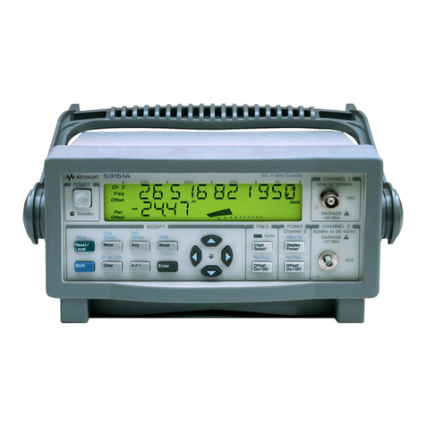
Agilent Technologies
Agilent Technologies 53151A User manual
Agilent Technologies
Agilent Technologies 53220A User manual
Agilent Technologies
Agilent Technologies 53210A User manual
