Atek SAS-S User manual

KK-SAS.002 02.03.21 Rev No:3
1
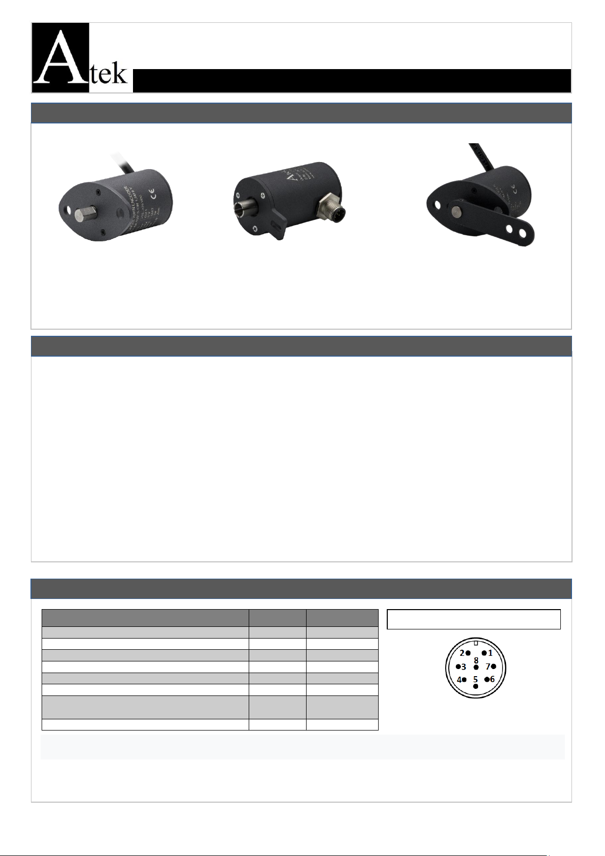
The SAS series encoders operate absolute. In other words, unlike the incremental systems, they do not lose their positions in
power outages and continue to measure from where they left off.
The SAS series single turn absolute rotary encoders offer highly flexible solutions in use, with different analog output signals,
shaft diameters and user-adjustable measuring range. The SAS single turn absolute rotary encoder with integrated reference
provides high quality feedback.
•The installation of the product is carried out by the customer who purchases the product, according to the wiring diagrams,
installation information, etc. in this manual.
•Maintenance and repair should be done by the technicians authorized by the manufacturer firm.
•There must be minimum distance between the sensor and control unit. Avoid additions except the suitable connector unless
it needs.
•Keep away the sensor cable from as high power energy cables, contactor, motor, switched power supplies, inductive and
capacitive noisy supplies.
•Shielding edge of the sensor cable must be ground connected.
•For not to damage the sensor, supply directions and voltage must be paid attention. Don’t energize before all connections
completed.
•Transport and storage should be at their original packaging and an ambient temperature of -20°C / + 70°C in such a way that
they will not be exposed to dust, humudity, impact, vibration, falling or water.
•Chemicals such as alcohol, thinner etc. should not be used for cleaning the product. The product should be wiped with a
damp cloth.
•The product may be damaged and may become unusable if used outside of the specifications in the user manual.
WARNINGS
SAS-B (SEMI HOLLOW SHAFT)
SAS –ANALOG OUTPUT
SINGLE TURN ABSOLUTE ROTARY ENCODER
USER MANUAL
GENEAL INFORMATIONS
SAS-S (SHAFT)
SAS-K (SLEEVED)
ELECTRICAL CONNECTION
Signal
Cable
M12 Connector
U+ (+15…+26 VDC)
Red
Pin 1
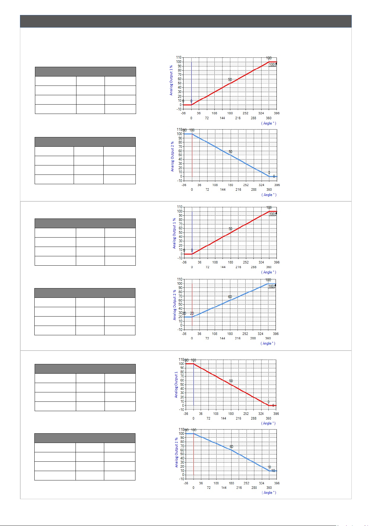
Output 1: 0.5-4.5 /0.1-10VDC / 4-20mA
Gray
Pin 2
GND (0V)
Black
Pin 3
Output 2: 0.5-4.5 /0.1-10VDC / 4-20mA
White
Pin 4
Directşon Change
Pink
Pin 5
Reset
Green
Pin 6
Programming Tips (these ends should not touch
each other and should not be connected anywhere)
Yellow, Blue
Pin 7 (N/C)
-
-
Pin 8 (N/C)
RESET: With the reset function you can set the desired location to 0. The reset terminal and GND are short-circuited for about
5 seconds and then disconnected. The sensor then accepts the current position as zero.
DIRECTION CHANGE: You can change the angle increase direction with the direction change function. The direction changing
terminal and GND are short-circuited for about 5 seconds and then disconnected.Thus, the sensor reverses the angle direction
(CW is CCW and CCW is CW).
M12 8 PIN MALE CONNECTOR

KK-SAS.002 02.03.21 Rev No:3
2
DETERMINATION OF OUTPUT SIGNAL FORM
Analog output signal forms can be specified according to request for 3 points as low point, middle point and high point. The
requested signal form must be specified at the order stage. Examples of output signal forms are shown below.
Note: The diagrams shown below are for illustrative purposes. Scale value can be selected between 0 ° - 360 ° and Output
value between 0% and 100%.
Analog Output 1
Point
Scale
Output
Low Point
0°
%0
Middle Point
180°
%50
High Point
360°
%100
Analog Output 2
Point
Scale
Output
Low Point
360°
%0
Middle Point
180°
%50
High Point
0°
%100
Analog Output 1
Point
Scale
Output
Low Point
0°
%0
Middle Point
180°
%50
High Point
360°
%100
Analog Output 2
Point
Scale
Output
Low Point
0°
%20
Middle Point
180°
%60
High Point
360°
%100
Analog Output 1
Point
Scale
Output
Low Point
0°
%100
Middle Point
180°
%50
High Point
360°
%0
Analog Output 2
Point
Scale
Output
Low Point
0°
%100
Middle Point
180°
%60
High Point
360°
%10

KK-SAS.002 02.03.21 Rev No:3
3
DIMENSIONS
SAS-K (SLEEVED)
SAS-B (SEMI HOLLOW SHAFT)
Analog Output 1
Point
Scale
Output
Low Point
0°
%0
Middle Point
180°
%100
High Point
360°
%0
Analog Output 2
Point
Scale
Output
Low Point
0°
%100
Middle Point
180°
%0
High Point
360°
%100
SAS-S (SHAFT)

KK-SAS.002 02.03.21 Rev No:3
4
Product
Description
SAS
Absolute Single Turn Rotary Encoder
User Manual
1 pcs
Working Principle
Hall Effect
Electrical Connection
8 x 0,14 mm2shielded cable or M12
8 pin socket
Supply Voltage
15 … 26 VDC
Output Load
For current output model; min 250 Ω
For voltage output model; min 1 KΩ
Current Consumption
40 mA
Maximum Speed
3000 rpm
Reverse Polarity Protection
Yes
Body Diameter
37 mm
*Measuring Range
0°... 360°
*Shaft Diameter
6 mm, 8 mm or 10 mm
Accuracy
±0,1°
Weight
≈150 gr
Repeatability
0,1°
Protection Class
IP 67
Angular Resolution
14 Bit
Operating Temperature
-20 …+70 °C
Answering Frequency
333 Hz
Relative Humidity
%10 ile %90
*Electrical Interface
4-20 mA, 0-10 V, 0.5- 4.5 V,
20-4 mA, 10-0 V, 4.5-0.5 V
Material
Body: Aluminium
Shaft: Stainless Steel
Note: The technical specifications indicated by (*) vary according to the selected model. The detailed code table is shown on page 4.
BOX CONTENT
Shaft or Shaft
Hollow Diameter (4)
6 : 6 mm
8 : 8 mm
10 : 10 mm
Disposal of Packagings: Packaging materials consist of recyclable materials. For providing recycling, please dispose waste
packagings to collecting points of authorized recycling facilities.
Disposal of E-Waste: This device is in conformity with WEEE Directive and consists of recyclable materials. This product should
not be disposed with general waste for preventing negative effects on enviroment and human health. This product should be
disposed to collecting points of authorized recycling facilities. Further information can be reached from authorized unit.
Output Signal 1 (1)
V : 0-10 VDC
V1 : 0-5 VDC
A : 4-20 mA
V3 : 0.5-4.5 VDC
NV : 10-0 VDC
NV1 : 5-0 VDC
NA : 20-4 mA
NV3 :4.5-0.5 VDC
NV3 :4.5-0.5 VDC
Shaft Type
S : Shaft
B : Semi Hollow Shaft
K : Sleeved
TECHNICAL SPECIFICATIONS
Manufacturer Firm’s and Authorized Service’s Title, Address Details
Firm: ATEK ELEKTRONİK SENSÖR TEKNOLOJİLERİ SANAYİ VE TİCARET A.Ş.
Address: Gebze OSB, 800. Sokak, No:814 Gebze/KOCAELİ/TURKEY
TEL: +90 262 673 76 00 FAX: +90 262 673 76 08
Web: www.ateksensor.com
E-mail: [email protected]
(1) The direction of the output signals can be changed optionally. In the coding, when ‘N’is placed at the beginning of the normal signal, it
refers to the opposite. For example; in case of V: 0-10 VDC, then NV:10-0 VDC. The Output 2 is optional.
(2) Reference point; refers to the selection of one of the starting, middle, or end points used for the scale of the analog outputs.
(3) Cable length can be requested to a minimum of 1.5 m.
(4) In SAS-S (shaft) and SAS-B (semi hollow shaft) model, the shaft diameter can be 6 mm, 8 mm or 10 mm;
In SAS-K (sleeved) model, the shaft diameter can be only 8 mm.
Electrical Connection(3)
1.5M : 1.5m cable
S14: M12 8 Pin socket
PRODUCT CODE TABLE
Body Diameter
037 : 37 mm
Socket
Direction
Y :Side
Connector
Reference Point (2)
S : Start
M : Middle
E: End
Output Signal 2 (Optional) (1)
No code : Output 2 is not used
V : 0-10 VDC
V1 : 0-5 VDC
A : 4-20 mA
V3 : 0.5-4.5 VDC
NV : 10-0 VDC
NV1 : 5-0 VDC
NA : 20-4 mA
NV3 :4.5-0.5 VDC
Model
SAS
SAS X XXX XX XXX XXX XXXX XXX X X
Angle Value
The desired value
between 0° and 360°
can be selected
Angle Increasing
Direction
CW : Clockwise
CCW : Counter
clockwise
This manual suits for next models
2
Other Atek Media Converter manuals
Popular Media Converter manuals by other brands

Antrica
Antrica ANT-37500 user manual

Cypress
Cypress DCT-9D Operation manual

Hall Research Technologies
Hall Research Technologies EX-HDU-WP user manual

Baumer
Baumer Hubner Berlin HMG 11 Mounting and operating instructions

Audio Note
Audio Note DAC2.1x Signature Owner's Information

Transition Networks
Transition Networks J/E-CF-02(SC) user guide