ATEQ VT30 User manual

Quick Reference Guide
VT30
TPM SERVICE TOOL
VT30
Version: MJC-1409-US2
QRG3814d

TABLE OF CONTENTS
Section A - GENERAL DESCRIPTION
A1 - Front face – page 3/10
A2 - Power Supply – page 4/10
A3 - USB connector – page 4/10
Section B - UPDATE THE TOOL
B1 - Install WebVT software – page 5/10
B2 - VT30 boot mode – page 5/10
B3 - Update the tool – page 6/10
Section C - TRIGGERING SENSOR(S)
C1 - Testing a TPM Sensor – page 7/10
C2 - Results Description – page 9/10

A
SECTION A - GENERAL DESCRIPTION
The principle of this instrument is to awaken and then retrieve data from smart valves
mounted on vehicle wheels, in order to check their identifiers.
The instrument interacts with the smart valves to assist technicians service Tire Pressure
Monitor Systems (TPMS). VT30 is capable to trigger all known sensors.
A1 - FRONT FACE
Lights
indicators
Keypad
LF Antenna
LCD
display
USB
connecto
r

A
A2 - POWER SUPPLY
The VT30 device operates with 9 Volts batteries 6LF22 / 6LR61 types, standard or
rechargeable.
Replace the battery or charge the rechargeable battery
when low bat light is flashing
Please recycle the batteries do not put them in the dustbin.
A3 - USB CONNECTOR
The USB connection allows firmware updates to be installed onto
the tool using the WebVT software (only in boot mode, see
below). TPM Sensor results can also be printed using this
software.

B
SECTION B - UPDATE THE TOOL
To update the tool, you must install the WebVT software on your PC.
B1 - INSTALL WEBVT SOFTWARE
1) Connect the TPMS tool to the USB port and power the tool ON.
2) Insert the CD, supplied with your tool, into the PC drive and click on the WebVT icon to start
the program.
3) A screen will appear that says “Welcome to the Install Shield Wizard for WebVT.” Click
“Next >”.
4) A window will appear to choose destination location, click “Next >”.
5) Follow instructions until the window with the “Finish” button appears.
6) Click “Finish” when the WebVT installation is complete.
Note: to order annual update software part number, please see your dealer for availability and pricing.
B2 - VT30 BOOT MODE
To update the tool with the WebVT software, you must put the VT30 into boot mode.
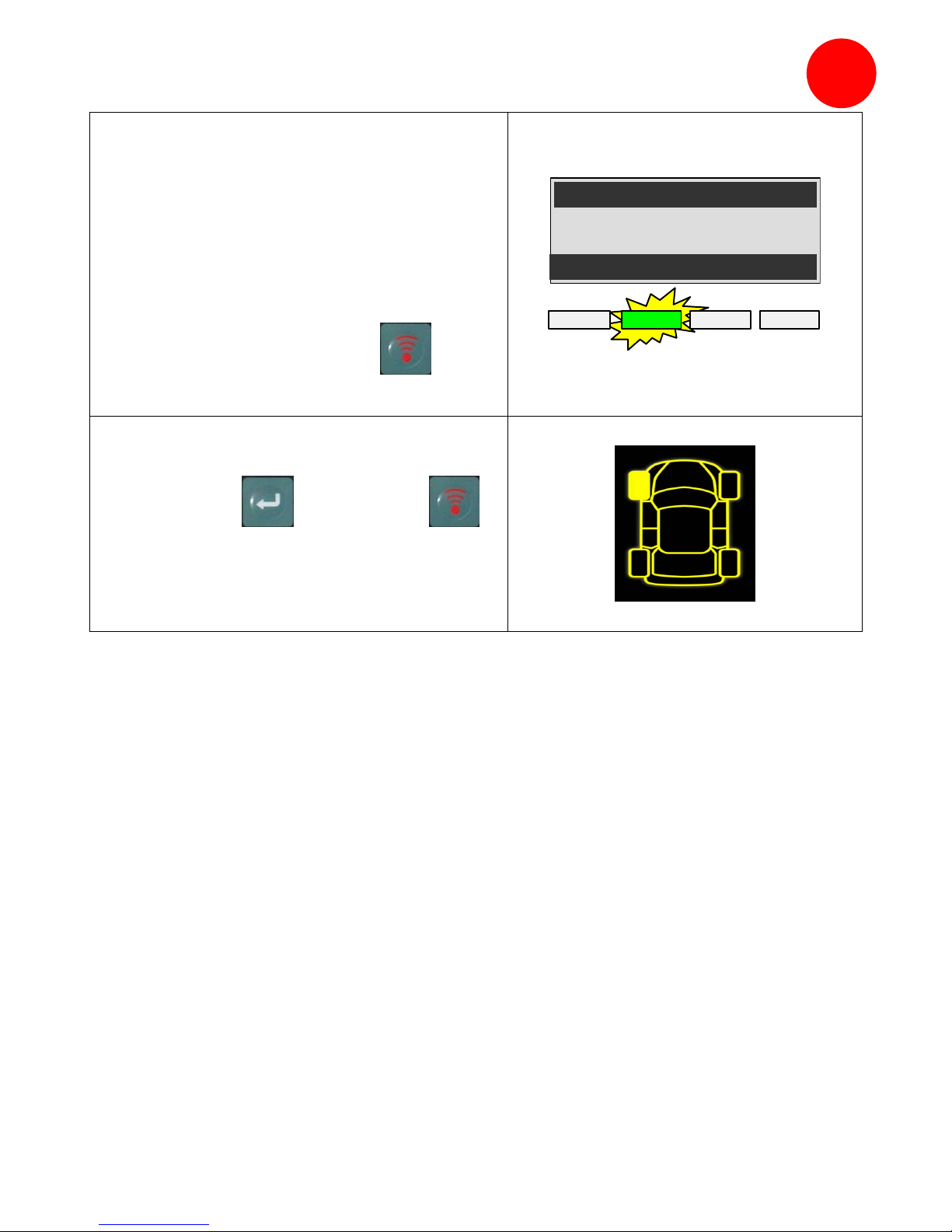
Step 2 – Device off, press and hold the
key and press and hold the .
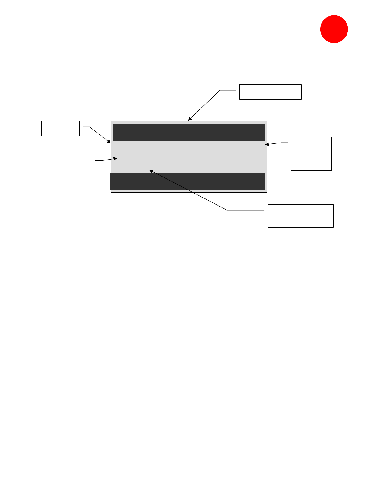
Once in boot mode the device displays
this screen (opposite picture).
BOOT
0010084
V1
.
04
USB : DISCONNECTED
S/N:K300-14000
Note: to switch off the device from this mode, press the Ckey.

B
B3 - UPDATE THE TOOL
Step 1 – Put the device into boot mode.
BOOT
0010084
V1
.
04
USB : DISCONNECTED
S/N:K300-14000
Step 2 – Connect the USB cable from
your PC to the device. The device
confirms the connection.
BOOT
0010084
V1
.
04
USB : CONNECTED
S/N:K300-14000
Step 3 – Start the WebVT software.
If your Internet connection needs a Login
and password, enter them.
Step 4 – The software is searching for
the device.
Once detected, the software displays the
device information.
If news versions are available for
download, the software prompts you to
update, follow instructions.
To update the device, hit the
key.

C
SECTION C - TRIGGERING SENSOR(S)
C1 - TESTING A TPM SENSOR
Step 1 – Select the "VEHICLE
SELECTION" menu and confirm selection
with the key.
MAIN MENU
>VEHICLE SELECTION
RKE TEST
SETTINGS
Step 2 – Select the vehicle brand on the
screen by using the or keys
and confirm selection with the key.
VEHICLE SELECTION
>FORD
GEELY
G
MC
Step 3 - Hold the tool within a few inches
from the TPM sensor. Some sensor may
require the tool position directly on the
rubber tire, over the valve stem.
Note: Some sensors are banded to the wheel and can be located 180° opposite the
valve stem. (Refer to owners manual)
Step 4 - Press the key. The tool will
begin to send LF trigger and the TX light
will flash. Depending on the sensor, the
tool will activate the sensor on the first or
last step. Each step identifies the
number of valve types used on the
vehicle brand.
FORD
LEFT FRONT
STEP: 2 / 4
(C) : STOP
TRIGGER PROCESSING
Low Bat Pass Fail Tx

C
Step 5 - The tool will vibrate/beep after
receiving the sensor information. The
tool will display the sensor ID, pressure,
and sensor state of the valve that is
triggered. If the tool does not receive the
correct information, the fail LED will
illuminate and you can restart the trigger
sequence by pressing the key
again.
CHRYSLER
LEFT FRONT
6FF79 32.24 PSI
78°F 1.0 g
BAT:OK 315 MHz
(C) MENU
(T) START () NEXT
Low Bat Pass Fail Tx
Step 6 - Follow the same procedure for
the rest of the three or four wheels by
pressing the key and then
key.
(Refer to vehicle owners manual or other
reference guides for TPM reset procedure.)

C
C2 - RESULTS DESCRIPTION
The picture below is an example of a valve data communication result:
FORD
LEFT FRONT
6FF79 32.24 PSI
78°F 1.0 g
BAT:OK 315 MHz
(C) MENU
(T) START () NEXT
Note: The VT30 will identify the sensor information that is transmitted. Not all sensors
transmit every piece of information shown.
Vehicle make
Tire
internal
pressure
Sensor's battery
status
Valve ID
Tire internal
temperature
Other manuals for VT30
1
Table of contents