ATH Cross Lift 50 User manual

OPERATING INSTRUCTIONS
ATH Cross Lift 50

® Copyright ATH-Heinl GmbH & Co. KG, 2019, All rights reserved / Misprints and technical changes reserved / As of: 2019-01
Manufacturer ATH-Heinl GmbH & CO.KG
- 2 -
Contents
1.0 INTRODUCTION ................................................................................................................... - 3 -
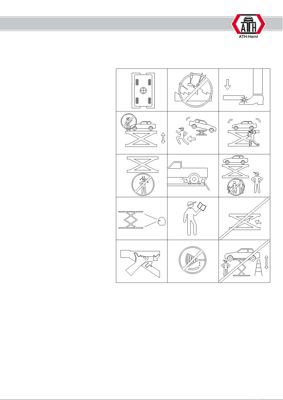
1.1 General Information ........................................................................................................... - 3 -
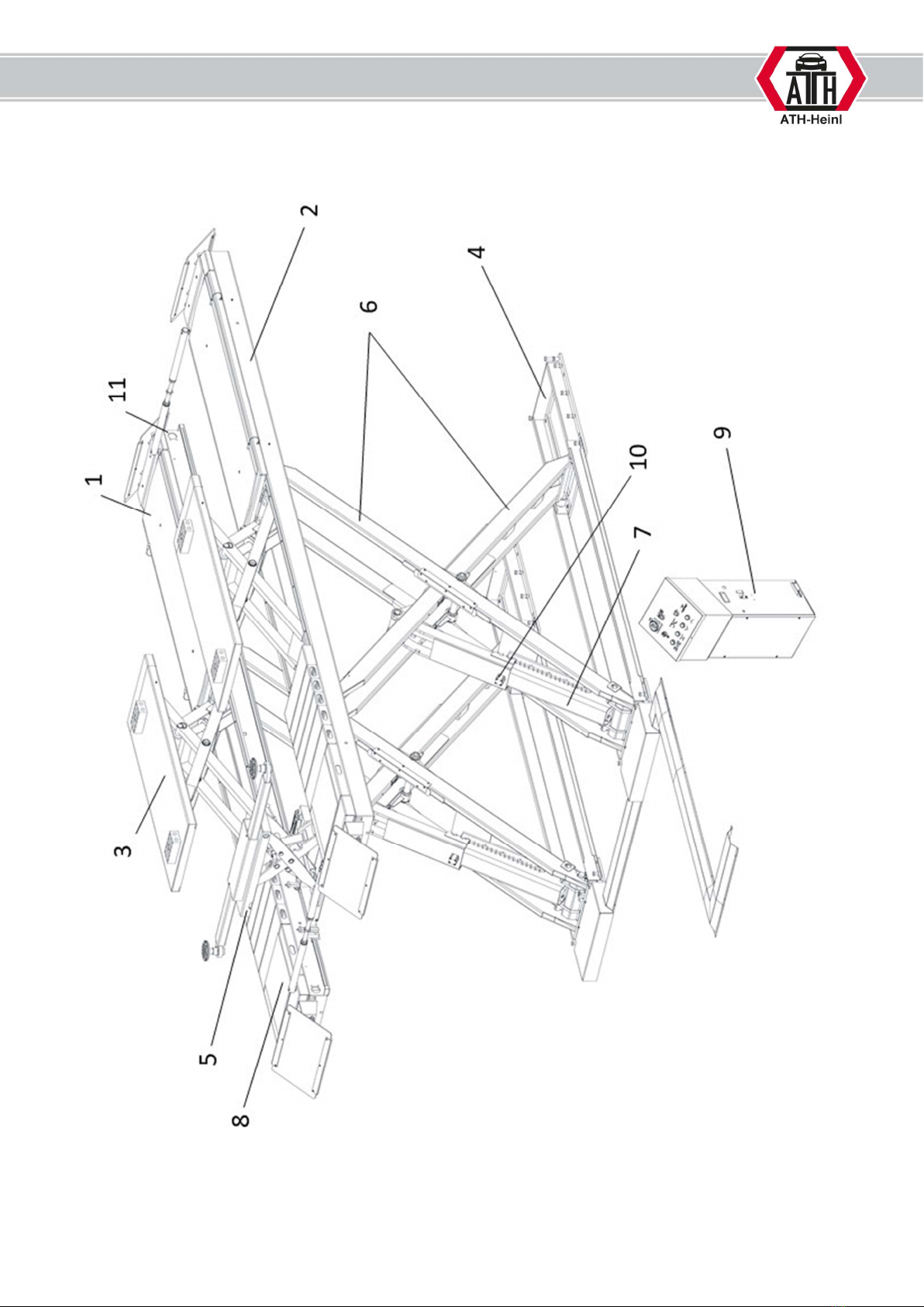
1.2 Description ........................................................................................................................ - 4 -
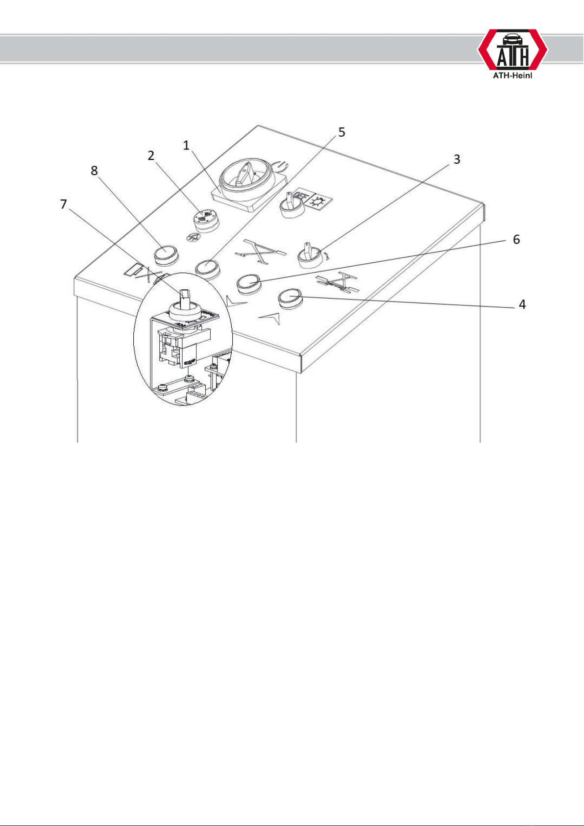
1.3 Operation.......................................................................................................................... - 6 -
1.4 Technical Data .................................................................................................................. - 9 -
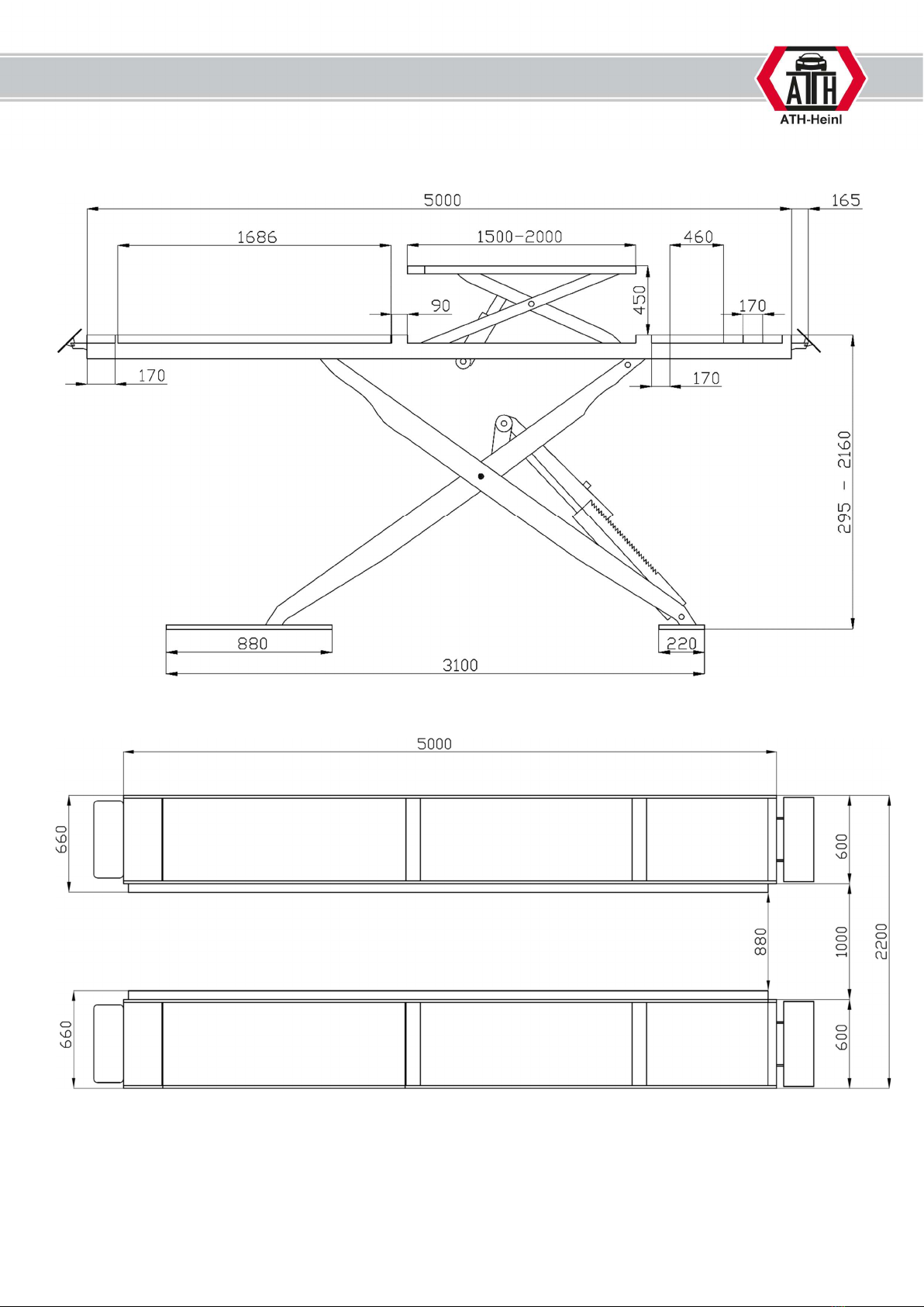
1.5 Scale Drawing ................................................................................................................. - 10 -
2.0 INSTALLATION ................................................................................................................... - 14 -
2.1 Transport & Storage Conditions ........................................................................................ - 14 -
2.2 Unpacking the machine .................................................................................................... - 14 -
2.3 Delivery Contents ............................................................................................................ - 15 -
2.4 Location .......................................................................................................................... - 17 -
2.5 Fixing ............................................................................................................................. - 18 -
2.6 Electrical Connection ........................................................................................................ - 18 -
2.7 Pneumatic Connection ...................................................................................................... - 19 -
2.8 Hydraulic Connection ....................................................................................................... - 19 -
2.9 Assembly ........................................................................................................................ - 19 -
2.10 Completion of Work ...................................................................................................... - 31 -
3.0 OPERATION ....................................................................................................................... - 32 -
3.1 Operating Instructions ..................................................................................................... - 32 -
3.2 Basic Information ............................................................................................................ - 33 -
4.0 MAINTENANCE ................................................................................................................... - 34 -
4.1 Consumables for installation, maintenance and servicing..................................................... - 34 -
4.2 Safety Regulations for Oil ................................................................................................. - 35 -
4.3 Notes ............................................................................................................................. - 36 -
4.4 Maintenance or Service Plan ............................................................................................. - 36 -
4.5 Troubleshooting / Error Display and Solutions .................................................................... - 37 -
4.6 Maintenance and Service Instructions ................................................................................ - 39 -
4.7 Disposal .......................................................................................................................... - 40 -
5.0 EG-/EU-KONFORMITÄTSERKLÄRUNG / EC-/EU-DECLARATION OF CONFORMITY...................... - 41 -
6.0 APPENDIX .......................................................................................................................... - 42 -
6.1 Pneumatic circuit diagram ................................................................................................ - 42 -
6.2 Electric circuit diagram ..................................................................................................... - 43 -
6.3 Hydraulic circuit diagram .................................................................................................. - 44 -
7.0 WARRANTY CARD ............................................................................................................... - 45 -
7.1 Scope of the Product Warranty ......................................................................................... - 46 -
8.0 INSPECTION LOG ............................................................................................................... - 47 -
8.1 Installation and Handover Log .......................................................................................... - 48 -
8.2 Inspection Plan ................................................................................................................ - 49 -
8.3 Visual inspection (authorised expert) ................................................................................. - 50 -
9.0 SPARE PART BOOK ............................................................................................................. - 54 -
10.0 NOTES ............................................................................................................................... - 87 -

® Copyright ATH-Heinl GmbH & Co. KG, 2019, All rights reserved / Misprints and technical changes reserved / As of: 2019-01
Manufacturer ATH-Heinl GmbH & CO.KG
- 3 -
1.0 INTRODUCTION
1.1 General Information
THESE INSTRUCTIONS ARE AN INTEGRAL PART OF THE MACHINE.
THEY MUST BE READ AND UNDERSTOOD BY THE USER.
NO LIABILITY IS ASSUMED FOR ANY DAMAGES CAUSED BY FAILURE TO
FOLLOW THESE INSTRUCTIONS OR THE VALID SECURITY PROVISIONS.
WARNING: Follow the instructions to prevent injury or damage.
TIP: Provides more information on functionality and tips for using the device efficiently.
Appropriate protective clothing must be worn for all work on the described system.

® Copyright ATH-Heinl GmbH & Co. KG, 2019, All rights reserved / Misprints and technical changes reserved / As of: 2019-01
Manufacturer ATH-Heinl GmbH & CO.KG
- 4 -
1.2 Description

® Copyright ATH-Heinl GmbH & Co. KG, 2019, All rights reserved / Misprints and technical changes reserved / As of: 2019-01
Manufacturer ATH-Heinl GmbH & CO.KG
- 5 -
1. Access ramp secondary side main lift
2. Access ramp control side main lift
These are moved upwards using the internal scissor lift system (6) and hydraulic cylinder (7)
3. Wheel-free lift
This facilitates additional vehicle lifting on the rocker rail.
4. Base frame
This secures the lifting system.
5. Jacking beam (optional)
This facilitates additional vehicle lifting on the axle or chassis.
6. Scissor lift system
7. Hydraulic lift cylinder
8. Cover plates
Allow optional wheel alignment rotary plates to be used
9. Control box
Contains the complete electrical control system. All buttons are protected by a front ring in order to
prevent the button from being pressed accidentally. Furthermore, all movements are immediately
stopped when the buttons
are released (dead man’s control).
Including hydraulic unit
The hydraulic oil in the tank is fed to the cylinders via a gear pump driven by the
engine. A lowering valve returns the oil to the tank.
10. Safety catches on the main and wheel-free lift
This system prevents the raised platform from lowering by more than 100 mm in the event of any
defects.
Electromagnets unlock the system each time it is lowered.
11. Light barrier
Ensures secure synchronisation of the two scissors

® Copyright ATH-Heinl GmbH & Co. KG, 2019, All rights reserved / Misprints and technical changes reserved / As of: 2019-01
Manufacturer ATH-Heinl GmbH & CO.KG
- 6 -
1.3 Operation
1. Lockable main switch with emergency stop function
to switch the lift on and off
and to prevent operation of the lift by unauthorised persons.
2. Alarm gives an acoustic and visual signal when the CE stop is reached
3. Selector switch
Choose between two drive versions
4. Lifting button
raises the lift
5. Parking button
parks the lift on safety catches. Depending on the setting of the selector switch, either the main or
wheel-free lift is activated.
6. Lowering button
After pressing the button for approx. 1-2 seconds, the safety catches are unlocked and then lowered.
An acoustic signal is also generated when the CE stop is reached.
7. Adjustment switch and work switch
Position: WORK indicates that the lift is in normal operation
Position: ADJ indicates that the lift is in adjustment mode
8. Switch for light barrier
Muting the light barrier for adjustment and/or installation measures

® Copyright ATH-Heinl GmbH & Co. KG, 2019, All rights reserved / Misprints and technical changes reserved / As of: 2019-01
Manufacturer ATH-Heinl GmbH & CO.KG
- 7 -
A = Motor
B = Pressure control valve
C = Solenoid valves D = Emergency manual pump
E = Lowering solenoid valve F = Levelling valves
G = Manometer

® Copyright ATH-Heinl GmbH & Co. KG, 2019, All rights reserved / Misprints and technical changes reserved / As of: 2019-01
Manufacturer ATH-Heinl GmbH & CO.KG
- 8 -
OPERATION
Safety instructions
1. Ensure there is correct weight
distribution of the vehicle
2. Changes to the lift of any kind are
not permitted
3. Leave the danger zone when
lowering the lift
4. No objects or persons may be
transported on the lift, the support
arms or on the vehicle that is being
lifted.
5. If there is a danger of the vehicle
falling, you must immediately leave
the danger zone
6. Prevent the lifted vehicle from
swaying significantly
7. The lift may only be operated by
trained personnel.
8. Use suitable roll protection
9. Only authorised persons are allowed
to enter the danger zone.
10. Proper maintenance and inspections
are necessary for safe work
11. Read and understand the operating
instructions before operating the lift
12. Do not work on damaged lifts
13. Keep the shearing points free when
moving the lift
14. Do not clean the lift under running
water.
15. The danger zone must be kept clear
when lifting and lowering

® Copyright ATH-Heinl GmbH & Co. KG, 2019, All rights reserved / Misprints and technical changes reserved / As of: 2019-01
Manufacturer ATH-Heinl GmbH & CO.KG
- 9 -
1.4 Technical Data
Model ATH Cross Lift 50HA
Load capacity of main lift 5,000 kg
Load capacity of wheel
-
free lift
4,000 kg
Lift time (for 2,000 kg)
70 s
Lowering time (for 2,000 kg) 60 s
Electric system 3/400V/50Hz
Control voltage DC24V
Motor 3.5 kW
rpm
1375
Motor housing
B14
Upstream fuse 3 C 16 A
Connection cable Min. 5 x 2.5 m²
Protection type IP 54
Flow rate
4.8 cm³/g
Working pressure ²
300 bar (max. 300 bar)
Required compressed air connection 7 bar
Recommended hydraulic oil Summer (15 °C to 45 °C): HVLP-D 46 (e.g.: Eni PRECIS HVLP-D)
Winter (under 10 °C): HVLP-D 32 (e.g.: Eni PRECIS HVLP-D)
Oil quantity
Approx. 18 l
Floor anchor Bolt anchor: M16 x 180 (e.g.: Atrion ABL-W 16-060-180)
Compound anchor: M16 x 190 (e.g.: Atrion AVA-W 16-045-190)
Number of anchors 16 units
Permissible sound level
≤ 80 dB
Weight
2,840 kg
² The factory set working pressure is adjusted to the maximum power rating. The pressure relief
valve must not be manipulated. Changing the settings can lead to serious damage.
If the stated rated load cannot be lifted, please contact our service team.

® Copyright ATH-Heinl GmbH & Co. KG, 2019, All rights reserved / Misprints and technical changes reserved / As of: 2019-01
Manufacturer ATH-Heinl GmbH & CO.KG
- 10 -
1.5 Scale Drawing
ATH Cross Lift 50 floor-level installation:

® Copyright ATH-Heinl GmbH & Co. KG, 2019, All rights reserved / Misprints and technical changes reserved / As of: 2019-01
Manufacturer ATH-Heinl GmbH & CO.KG
- 11 -
ATH Cross Lift 50 elevated installation:

® Copyright ATH-Heinl GmbH & Co. KG, 2019, All rights reserved / Misprints and technical changes reserved / As of: 2019-01
Manufacturer ATH-Heinl GmbH & CO.KG
- 12 -
ATH Cross Lift 50 Plus floor-level installation:

® Copyright ATH-Heinl GmbH & Co. KG, 2019, All rights reserved / Misprints and technical changes reserved / As of: 2019-01
Manufacturer ATH-Heinl GmbH & CO.KG
- 13 -
ATH Cross Lift 50 Plus elevated installation:

® Copyright ATH-Heinl GmbH & Co. KG, 2019, All rights reserved / Misprints and technical changes reserved / As of: 2019-01
Manufacturer ATH-Heinl GmbH & CO.KG
- 14 -
2.0 INSTALLATION
The machine must be installed by an authorised person according to the instructions.
The operating instructions (including the log) are an important part
of the machine / product.
!!!PLEASE STORE CAREFULLY!!!
The product must be checked after completion of the installation, handover, if necessary briefing and then
regularly in accordance with the applicable regulations and legal provisions in the country of operation by a
suitable and approved company or facility.
2.1 Transport & Storage Conditions
When transporting and positioning the machine, always use suitable lifting and material handling
equipment and consider the machine’s centre of gravity.
The machine should only be transported with the original packaging.
Data: 2.550 kg
Width
700 mm
Length
5.000 mm
Height 1.440 mm
Storage temperature -10 to +50 °C
2.2 Unpacking the machine
Remove the top cover of the packaging and make sure that no damage has occurred
during transport.
Remove the safety bolt to remove the machine from the pallet / rack.
Use a suitable lifting device (possibly with a stopping rope) to lower the machine from the
pallet / frame.
The packaging material used for the machine should be stored carefully.
Keep the packaging material out of the reach of children as it may be hazardous.

® Copyright ATH-Heinl GmbH & Co. KG, 2019, All rights reserved / Misprints and technical changes reserved / As of: 2019-01
Manufacturer ATH-Heinl GmbH & CO.KG
- 15 -
2.3 Delivery Contents
Basic package with:
2 x pairs of scissors including integrated cylinders
Dimensions (L x W x H): 5100 x 7000 x 300 mm
Weight: 700 kg
1 x package with control box, hydraulic and pneumatic hoses:
Dimensions (L x W x H): 400 x 540 x 1,140 mm
Weight: 130 kg
1 x package with accessories, ramps and bridging track sections.
Dimensions (L x W x H): 400 x 540 x 1,140 mm
Weight: 130 kg
OPTIONAL
Scissor jacking beam 1 x 1000 x 600 x 400 mm Weight: 130 kg

® Copyright ATH-Heinl GmbH & Co. KG, 2019, All rights reserved / Misprints and technical changes reserved / As of: 2019-01
Manufacturer ATH-Heinl GmbH & CO.KG
- 16 -
If something is missing from your delivery, please contact our sales department.
Tips for transport and storage:
- Lift carefully. Support the weight properly using suitable equipment that is in good order and condition.
- Avoid unexpected raises and jerky movements. Beware of bumps, gutters, etc.
- Store the removed packaging at a collection point inaccessible to children and animals until it is
disposed.
- Storage temperature: 10 °C~+40 °C

® Copyright ATH-Heinl GmbH & Co. KG, 2019, All rights reserved / Misprints and technical changes reserved / As of: 2019-01
Manufacturer ATH-Heinl GmbH & CO.KG
- 17 -
2.4 Location
The machine should be kept away from flammable and explosive materials, as well as from sunlight and
intense light. The machine should be placed in a well-ventilated location.
The machine must be set up on sufficiently firm ground, if necessary, according to the minimum
requirements of the information given in the foundation plan.
In addition to the ground conditions, the guidelines and instructions of the accident prevention regulations
as well as the workplace regulations must be observed when selecting an installation site.
When assembling on floor coverings, check their load-bearing capacity. A construction expert should be
consulted for inspection when mounting on floor coverings.
The machine should only be mounted and used within closed rooms. It has no corresponding safety
features (e.g. IP protection, galvanised design, etc.).
Temperature 4-40 °C
Sea level
< 1500 m
Humidity 50% at 40 °C – 90% at 20 °C
Drawing

® Copyright ATH-Heinl GmbH & Co. KG, 2019, All rights reserved / Misprints and technical changes reserved / As of: 2019-01
Manufacturer ATH-Heinl GmbH & CO.KG
- 18 -
Safety area
min. 1 m
Permissible operating temperatures: 10 - 40 °C
Maximum permitted humidity: ≤80 % at 30 °C
Height above sea level:
≤ 2000 m
Power connection & earthing cable (see technical data) is to be installed as a connector system (socket and
plug) or a fixed connection.
Required supply
See technical data
The lift must not be installed in damp, wet or potentially explosive areas.
The lift may only be installed indoors and may not be installed outdoors.
2.5 Fixing
General and local regulations must be observed. Therefore,
these steps should only
be
carried out by a trained professional.
The machine must be set up and fixed on sufficiently firm ground, if necessary, according to the minimum
requirements of the information given in the foundation plan.
The machine must be fastened at the points provided with suitable or specified fastening material.
In addition to the ground conditions, the guidelines and instructions of the accident prevention regulations
as well as the workplace regulations must be observed when selecting an installation site.
When assembling on floor coverings, check their load-bearing capacity. A construction expert should be
consulted for inspection when mounting on floor coverings.
2.6 Electrical Connection
General and local regulations must be observed. Therefore, these steps may only be
carried out by a trained professional.
Pay attention to the necessary supply line (see technical data).
The connection should be made with a 230V Schuko plug or 5-phase 16 A CEE plug (partially included).
Voltage deviations should be 0.9 - 1.1 times the nominal voltage range and the frequency deviation should
be 0.99 - 1.01 times the frequency range.
Necessary protective measures must be taken to guarantee this.
At the end of the work, the direction that the motor rotates must be checked.

® Copyright ATH-Heinl GmbH & Co. KG, 2019, All rights reserved / Misprints and technical changes reserved / As of: 2019-01
Manufacturer ATH-Heinl GmbH & CO.KG
- 19 -
2.7 Pneumatic Connection
For all pneumatic systems, a compressed air maintenance unit (partially included) must
be installed between the supply line and the system.
The air pressure of the supply line must at least correspond to the technical data.
The compressed air maintenance unit must be set correctly and checked.
The compressed air maintenance unit must be serviced at regular intervals.
The maximum or minimum pressure ensures perfect functioning without any damage.
2.8 Hydraulic Connection
Before the system is put into operation or operated for the first time with oil, the
following must be observed with regard to the optimal, trouble-free and almost air-free
functioning
All hydraulic lines must be connected and tightened according to the hydraulic plan and, if applicable
according to the hose designation.
All hydraulic lines and cylinders must be vented according to the hydraulic plan and, if applicable, according
to the hose designation.
In order to ensure the faultless and safe functioning of the system and the hose assemblies used, the
hydraulic fluids used must comply with the specific instructions and recommendations of the manufacturer.
Used media that do not meet the specific requirements or which have unauthorised contamination damage
the entire hydraulic system and shorten the service life of the hydraulic systems used. Warning: (system
contamination can also occur when oil is refilled)
The minimum requirement and minimum oil quantity must be checked and ensured.
2.9 Assembly
These instructions are no
t to be viewed as assembly instructions; hints and tips are
provided only for trained expert installers. Suitable clothing and personal protection must
be worn for the following work.
Incorrect installation and settings lead to exclusion of liability and warranty.
Partly pre-assembled machines must be checked, introduced and approved by a competent person before
commissioning.
Machine assembly must be carried out by a qualified and competent person.

® Copyright ATH-Heinl GmbH & Co. KG, 2019, All rights reserved / Misprints and technical changes reserved / As of: 2019-01
Manufacturer ATH-Heinl GmbH & CO.KG
- 20 -
INSTALLATION
Foundation
Table of contents
Other ATH Lifting System manuals