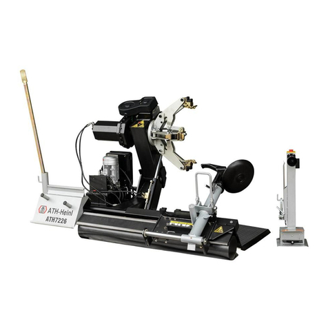
ATH M126 User manual

OPERATING INSTRUCTIONS
ATH M126

® Copyright ATH-Heinl GmbH & Co. KG, 2019, All rights reserved / Misprints and technical changes reserved / As of: 2019-03
Manufacturer ATH-Heinl GmbH & CO.KG
- 2 -
Contents
1.0 INTRODUCTION ................................................................................................................... - 3 -
1.1 General Information ........................................................................................................... - 3 -
1.2 Description ........................................................................................................................ - 4 -
1.3 Operation.......................................................................................................................... - 6 -
1.4 Technical Data ................................................................................................................ - 15 -
1.5 Scale Drawing ................................................................................................................. - 15 -
2.0 INSTALLATION ................................................................................................................... - 16 -
2.1 Transport & Storage Conditions ........................................................................................ - 16 -
2.2 Unpacking the machine .................................................................................................... - 17 -
2.3 Delivery Contents ............................................................................................................ - 17 -
2.4 Location .......................................................................................................................... - 18 -
2.5 Fixing ............................................................................................................................. - 19 -
2.6 Electrical Connection ........................................................................................................ - 19 -
2.7 Pneumatic Connection ...................................................................................................... - 19 -
2.8 Hydraulic Connection ....................................................................................................... - 20 -
2.9 Assembly ........................................................................................................................ - 20 -
2.10 Completion of Work ...................................................................................................... - 22 -
3.0 OPERATION ....................................................................................................................... - 23 -
3.1 Operating Instructions ..................................................................................................... - 23 -
3.2 Basic Information ............................................................................................................ - 24 -
4.0 MAINTENANCE ................................................................................................................... - 25 -
4.1 Consumables for installation, maintenance and servicing..................................................... - 25 -
4.2 Safety Regulations for Oil ................................................................................................. - 26 -
4.3 Notes ............................................................................................................................. - 27 -
4.4 Maintenance or Service Plan ............................................................................................. - 27 -
4.5 Troubleshooting / Error Display and Solutions .................................................................... - 28 -
4.6 Maintenance and Service Instructions ................................................................................ - 29 -
4.7 Disposal .......................................................................................................................... - 30 -
5.0 EG-/EU-KONFORMITÄTSERKLÄRUNG / EC-/EU-DECLARATION OF CONFORMITY...................... - 31 -
6.0 APPENDIX .......................................................................................................................... - 32 -
6.1 Pneumatic circuit diagram ................................................................................................ - 32 -
6.2 Electric circuit diagram ..................................................................................................... - 32 -
6.3 Hydraulic circuit diagram .................................................................................................. - 33 -
7.0 WARRANTY CARD ............................................................................................................... - 34 -
7.1 Scope of the Product Warranty ......................................................................................... - 35 -
8.0 INSPECTION LOG ............................................................................................................... - 36 -
8.1 Installation and Handover Log .......................................................................................... - 37 -
8.2 Inspection Plan ................................................................................................................ - 38 -
8.3 Visual inspection (authorised expert) ................................................................................. - 39 -
9.0 SPARE PART BOOK ............................................................................................................. - 43 -
10.0 NOTES ............................................................................................................................... - 57 -

® Copyright ATH-Heinl GmbH & Co. KG, 2019, All rights reserved / Misprints and technical changes reserved / As of: 2019-03
Manufacturer ATH-Heinl GmbH & CO.KG
- 3 -
1.0 INTRODUCTION
1.1 General Information
THESE INSTRUCTIONS ARE AN INTEGRAL PART OF THE MACHINE.
THEY MUST BE READ AND UNDERSTOOD BY THE USER.
NO LIABILITY IS ASSUMED FOR ANY DAMAGES CAUSED BY FAILURE TO
FOLLOW THESE INSTRUCTIONS OR THE VALID SECURITY PROVISIONS.
WARNING: Follow the instructions to prevent injury or damage.
TIP: Provides more information on functionality and tips for using the device efficiently.
Appropriate protective clothing must be worn for all work on the described system.

® Copyright ATH-Heinl GmbH & Co. KG, 2019, All rights reserved / Misprints and technical changes reserved / As of: 2019-03
Manufacturer ATH-Heinl GmbH & CO.KG
- 4 -
1.2 Description
1 Lifting column Carries the lifting carriage
2 Lifting carriage Holder for assembly tools
3
Assembly rollers
For mounting or removing tyres
4
Mounting bracket
For fixing the machine to the floor
5 Hydraulic cylinder For swivelling the clamping arms
6 Clamping jaws Clamping mechanism
7 Mounting finger For mounting or removing tyres
8
Swivel arm
For the mounting finger, depending on whether this is
used or not.
9 Chuck Mechanism for swivelling and turning the wheel
Control box Hydraulic unit with operating lever
10 Control lever for mounting finger For changing the angle of the mounting finger
11
Control lever for lifting carriage
For lifting and lowering the lifting carriage
12
Control lever for swivelling the chuck
For swivelling the chuck into receiving or working
position
13 Control lever for rotating the chuck For rotating the chuck
14
Control lever for clamping
For clamping the wheel
15
Manometer
Displays the current operating pressure
16 Control box Contains all electrical components
17 Emergency stop For switching off the machine in an emergency

® Copyright ATH-Heinl GmbH & Co. KG, 2019, All rights reserved / Misprints and technical changes reserved / As of: 2019-03
Manufacturer ATH-Heinl GmbH & CO.KG
- 5 -
Operating the tyre changer
1 Control unit for opening and closing the clamping jaws.
2 Control unit for rotating the clamping jaws in a clockwise or counter clockwise direction
3 Control unit for swivelling the clamping jaws
4 Control unit for lifting and lowering the lifting carriage
5
Control unit for the hydraulic mounting finger
2
1
4
4
3

® Copyright ATH-Heinl GmbH & Co. KG, 2019, All rights reserved / Misprints and technical changes reserved / As of: 2019-03
Manufacturer ATH-Heinl GmbH & CO.KG
- 6 -
1.3 Operation
1.3.1 Review of the different functions
Before using the tyre changer, control and check all functions with the operating part to ensure the
machine is working properly. This should be done before each mounting process.
WARNING!
When operating the tyre changer, pay attention to all moving parts. Make
sure there is enough safety clearance so that the moving parts do not contact
you. Make sure there are no other people in the work area.
WARNING!
Always keep enough safety clearance when loosening the mounting arm so
that it does not tilt outwards under tension.
WARNING!
Ensure that there are no persons or objects in the working area of the
machine.
WARNING!
When closing the chuck, the process must be stopped immediately when the
minimum position is reached.
When tightening the rim, stop immediately when the maximum pressure is
reached. For aluminium rims, check the clamping pressure and set it lower if
required.
Failure to comply with this instruction may result in serious damage to the
tyre changer.
1.3.2 Precautions during tyre mounting
Before mounting the tyre, the following precautions must be observed:
Only mount undamaged, clean, dry rims and tyres that are in good condition.
Remove old balance weights.
Check rim and tyre for damage, especially aluminium rims. Do not mount if damaged.
Check that the rim and tyre size match.
Before dismantling, let all air out of the tyre.
Before mounting, coat the rim and tyre well with tyre lubricant to avoid damage.
Always use a new valve.
The tyre changer is not splash-proof, so do not clean wheels on the machine with water jets.

® Copyright ATH-Heinl GmbH & Co. KG, 2019, All rights reserved / Misprints and technical changes reserved / As of: 2019-03
Manufacturer ATH-Heinl GmbH & CO.KG
- 7 -
1.3.3. Operating the tyre changer
This instruction manual only details the function of the machine; it does not replace professional training
and qualification of operating personnel.
WARNING!
All tyre changers have movable or adjustable controls. It is essential to ensure
that the operator always finds a working position where he can safely track
and view all work steps.
1.3.4. Clamping the wheel
WARNING!
When tightening the rim, make sure that the clamping jaws are correctly
positioned on the rim to prevent the wheel from falling down.
There are different types of truck rims (Fig. 8 E/1-E6).
Use the four clamping jaws to select the appropriate clamp for the rim.
Place the tyre on the inside of the table for the mounting arm.
Move the table until just before the clamping jaws.
Lower the clamping head to the centre of the rim.
Open the clamping jaws until they are smaller than the diameter of the mounting hole.
Slide the tyre over the clamping jaws and open until the tyre is secure.
Check that the rims sit correctly in all four jaws and that the tyre turns smoothly, otherwise it is not
possible to assemble.

® Copyright ATH-Heinl GmbH & Co. KG, 2019, All rights reserved / Misprints and technical changes reserved / As of: 2019-03
Manufacturer ATH-Heinl GmbH & CO.KG
- 8 -
WARNING!
Note that the most secure tension is always at the inner hole.
WARNING!
Never leave the work area while the wheel is still raised or tensioned.
Clamping the wheel
In principle, the guidelines of the German Rubber Industry Trade Association
(Wirtschaftsverband der deutschen Kautschukindustrie) should be observed when
removing tyres.
Handling heavy loads:
- Loads up to 35 kg may be handled by one person, no special handling aids are required
(see also EN 1005);
- Loads between 35 and 70 kg should be handled by two persons (also check the spatial
requirements and instructions) or using the transport / lifting aids provided;
- Loads over 70 kg require a handling or lifting system.
WARNING!
When tightening the rim, make sure that the clamping jaws are correctly
positioned on the rim to prevent the wheel from falling down.
There are different types of truck rims (Fig. 8 E/1-E6).
Use the four clamping jaws to select the appropriate clamp for the rim.

® Copyright ATH-Heinl GmbH & Co. KG, 2019, All rights reserved / Misprints and technical changes reserved / As of: 2019-03
Manufacturer ATH-Heinl GmbH & CO.KG
- 9 -
Move the assembly tower all the way up.
Place the wheel in front of the machine’s clamping jaws and clamp
by operating the clamping lever.
In the case of aluminium rims, please use the enclosed
clamping ring
The wheel can then be brought into a 90° position by operating the
lever for swivelling.
Tyre bead breaker
Preparation
Check the following points before using the device:
- Check whether the power supply is connected properly.
Unscrew the valve insert on the wheel valve and let out all the air.

® Copyright ATH-Heinl GmbH & Co. KG, 2019, All rights reserved / Misprints and technical changes reserved / As of: 2019-03
Manufacturer ATH-Heinl GmbH & CO.KG
- 10 -
First, the tyre bead must be completely pressed off from both sides
of the rim with the bead breaker roller. During this process, the
mounting paste is applied to the rim and the tyre bead.
Start with the upper bead.
Place the bead breaker roller on the outside of the tyre. In order to
complete the assembly without any damage, the roller must be
positioned around 1 cm from the edge of the rim flange.
>
>
Operate the lever for lowering the assembly tower until the tyre is
released from the rim.
Begin the rotation process to release the entire tyre from the rim.
Operate the lever for lifting the assembly tower to release the
pressure from the tyre and allow for swivelling.
>
>
Swivel the wheel forward and lower the assembly tower until the
bead breaker roller is under the wheel. The wheel can then be
swivelled back towards the tower in order to press off the lower
bead.
Press off the lower tyre bead.
Place the bead breaker roller on the outside of the tyre. In order to
complete the assembly without any damage, the roller must be
positioned around 1 cm from the edge of the rim flange.
>
Operate the lever for lifting the assembly tower until the tyre is
released from the rim.
Begin the rotation process to release the entire tyre from the rim.
Then continue with the removal procedure.

® Copyright ATH-Heinl GmbH & Co. KG, 2019, All rights reserved / Misprints and technical changes reserved / As of: 2019-03
Manufacturer ATH-Heinl GmbH & CO.KG
- 11 -
Removing the tyre with the bead breaker roller
+
If the tyre is not being used again or reconditioned, it is
possible to completely push it off the rim from below. This
procedure may result in damage to the inner steel structure.
When the bead breaker roller is in the lower position (last step of
bead breaking), it is possible to continue the removal process by
pressing the lifting lever.
The tyre must be constantly rotated during this process.
Removing the tyre with the mounting finger
Swivel the finger into position ready for mounting.
&
Bring the mounting finger into a 90° position so that it can be
driven between the tyre and rim to grip the tyre with the hook.

® Copyright ATH-Heinl GmbH & Co. KG, 2019, All rights reserved / Misprints and technical changes reserved / As of: 2019-03
Manufacturer ATH-Heinl GmbH & CO.KG
- 12 -
>
> >
Lower the assembly tower until the tyre catches.
Where necessary, the angle of the mounting finger can be altered
to prevent the tyre from slipping off the finger.
The tower can then be moved upwards.
The lower roller pushes the tyre upwards and supports the removal
process.
At the same time, the lower bead can be removed with the roller.
Mounting the tyre
Cover the tyre and the wheel rim in a sufficient amount of
mounting paste.

® Copyright ATH-Heinl GmbH & Co. KG, 2019, All rights reserved / Misprints and technical changes reserved / As of: 2019-03
Manufacturer ATH-Heinl GmbH & CO.KG
- 13 -
Position the tyre such that it is in the upper recess of the rim.
Ensure that the tyre does not slip off the rim when lifting
>
+
Swivel the wheel and tyre upwards as one and press the tyre under
the rim flange using the roller.
If necessary, the hold-down clamp can be attached at this point.
In the case of sharp-edged rims (e.g. agricultural rims),
we recommend using the finger to mount the upper bead in order
to avoid damage to the tyre bead

® Copyright ATH-Heinl GmbH & Co. KG, 2019, All rights reserved / Misprints and technical changes reserved / As of: 2019-03
Manufacturer ATH-Heinl GmbH & CO.KG
- 14 -
Inflating the tyre
The maximum tyre pressure may not exceed 3.5 bar.
All parts of the body should be kept away from the tyre.
During operation the noise level can reach 85 dB (A), so the operator should take
appropriate protective measures.
A tyre explosion under pressure can be very dangerous. A tyre explosion can cause
serious injury to the operator and may even be fatal.
Inflate the tyre only after placing the wheel in an approved inflation chamber.
Do not stand in the vicinity of the wheel or cage during inflation.
Do not exceed the maximum inflation pressure recommended by the manufacturer.
Ensure that the tyre has been fully lubricated.
Start the inflation process.
If the air volume of the tyre inflator is not sufficient to push the tyre
over the wheel rim, you can increase the air volume by removing
the inner valve. This must be replaced quickly afterwards.
Ensure that the tyre has been inflated to the correct pressure.
Consult the manufacturer’s specifications to establish this.
If the tyre pressure is too low, this can lead to increased wear and
decrease the service life of the tyre. The inside of the tyre can also
be damaged.
The tyre pressure must be checked once a week.
Only check the tyre pressure at normal tyre temperatures (i.e. the
vehicle has not been driven for more than an hour and not more
than 2-3 km)

® Copyright ATH-Heinl GmbH & Co. KG, 2019, All rights reserved / Misprints and technical changes reserved / As of: 2019-03
Manufacturer ATH-Heinl GmbH & CO.KG
- 15 -
1.4 Technical Data
Clamping range (A) 5-15 inches / 127-381 mm
Rim diameter (B) 19-26 inches
Max. entry width (D) 18 inches / 460 mm
Max. wheel diameter (C) 55 inches / 1400 mm
Max. wheel weight 380 kg
Bead breaking force of
roller
lifting/lowering
Approx. 4000 / 2000 kg
Contact force of finger 2000 kg
Mounting speed 6.8 rpm
Operating pressure 14 MPa / 140 bar
Max. operating pressure 14 MPa / 150 bar
Torque (max.) 1860 Nm (2700 Nm)
Power supply 3 Ph 400 V / 50/60 Hz – 16
A
Full load current 30 A
Short-circuit current
capacity 6 kA
Hydraulic pump 3.0 kW
Hydraulic motor 2.4/3.0 kW
Size of hydraulic tank 15 litres
Noise emission < 70 dB(A)
Net weight 485 kg
Gross weight 560 kg
1.5 Scale Drawing

® Copyright ATH-Heinl GmbH & Co. KG, 2019, All rights reserved / Misprints and technical changes reserved / As of: 2019-03
Manufacturer ATH-Heinl GmbH & CO.KG
- 16 -
2.0 INSTALLATION
The machine must be installed by an authorised person according to the instructions.
The operating instructions (including the log) are an important part
of the machine / product.
!!!PLEASE STORE CAREFULLY!!!
The product must be checked after completion of the installation, handover, if necessary briefing and then
regularly in accordance with the applicable regulations and legal provisions in the country of operation by a
suitable and approved company or facility.
2.1 Transport & Storage Conditions
When transporting and positioning the machine, always use suitable lifting and material handling
equipment and consider the machine’s centre of gravity.
The machine should only be transported with the original packaging.
Data:
Width
1150 mm
Length
1630 mm
Height 1270 mm
Storage temperature -25 to +55 °C

® Copyright ATH-Heinl GmbH & Co. KG, 2019, All rights reserved / Misprints and technical changes reserved / As of: 2019-03
Manufacturer ATH-Heinl GmbH & CO.KG
- 17 -
2.2 Unpacking the machine
Remove the top cover of the packaging and make sure that no damage has occurred
during transport.
Remove the safety bolt to remove the machine from the pallet / rack.
Use a suitable lifting device (possibly with a stopping rope) to lower the machine from the
pallet / frame.
The packaging material used for the machine should be stored carefully.
Keep the packaging material out of the reach of children as it may be hazardous.
2.3 Delivery Contents
1) Tyre lever
2) Hold
-
down clamp (plastic)
3) Mounting paste 4) Funnel for pouring in hydraulic oil
5) Brush for mounting paste 6) Aluminium clamping ring Ø 280 mm
7) Plastic contact strip for mounting finger 8) OPTIONAL: Instructional video
1
2
7
5
8
4
3
6

® Copyright ATH-Heinl GmbH & Co. KG, 2019, All rights reserved / Misprints and technical changes reserved / As of: 2019-03
Manufacturer ATH-Heinl GmbH & CO.KG
- 18 -
2.4 Location
The machine should be kept away from flammable and explosive materials, as well as from sunlight and
intense light. The machine should be placed in a well-ventilated location.
The machine must be set up on sufficiently firm ground, if necessary, according to the minimum
requirements of the information given in the foundation plan.
In addition to the ground conditions, the guidelines and instructions of the accident prevention regulations
as well as the workplace regulations must be observed when selecting an installation site.
When assembling on floor coverings, check their load-bearing capacity. A construction expert should be
consulted for inspection when mounting on floor coverings.
The machine should only be mounted and used within closed rooms. It has no corresponding safety
features (e.g. IP protection, galvanised design, etc.).
Temperature 4-40 °C
Sea level
< 1500 m
Humidity 50% at 40 °C – 90% at 20 °C
Drawing

® Copyright ATH-Heinl GmbH & Co. KG, 2019, All rights reserved / Misprints and technical changes reserved / As of: 2019-03
Manufacturer ATH-Heinl GmbH & CO.KG
- 19 -
2.5 Fixing
General and local regulations must be observed. Therefore, these steps should only be
carried out by a trained professional.
The machine must be set up and fixed on sufficiently firm ground, if necessary, according to the minimum
requirements of the information given in the foundation plan.
The machine must be fastened at the points provided with suitable or specified fastening material.
In addition to the ground conditions, the guidelines and instructions of the accident prevention regulations
as well as the workplace regulations must be observed when selecting an installation site.
When assembling on floor coverings, check their load-bearing capacity. A construction expert should be
consulted for inspection when mounting on floor coverings.
2.6 Electrical Connection
General and local regulations must be observed. Therefore, these steps may only be
carried out by a trained professional.
Pay attention to the necessary supply line (see technical data).
The connection should be made with a 230V Schuko plug or 5-phase 16 A CEE plug (partially included).
Voltage deviations should be 0.9 - 1.1 times the nominal voltage range and the frequency deviation should
be 0.99 - 1.01 times the frequency range.
Necessary protective measures must be taken to guarantee this.
At the end of the work, the direction that the motor rotates must be checked.
2.7 Pneumatic Connection
For all pneumatic systems, a compressed air maintenance unit (partially included) must
be installed between the supply line and the system.
The air pressure of the supply line must at least correspond to the technical data.
The compressed air maintenance unit must be set correctly and checked.
The compressed air maintenance unit must be serviced at regular intervals.
The maximum or minimum pressure ensures perfect functioning without any damage.

® Copyright ATH-Heinl GmbH & Co. KG, 2019, All rights reserved / Misprints and technical changes reserved / As of: 2019-03
Manufacturer ATH-Heinl GmbH & CO.KG
- 20 -
2.8 Hydraulic Connection
Before the system is put into operation or operated for the first time with oil, the
following must be observed with regard to the optimal, trouble-free and almost air-free
functioning
All hydraulic lines must be connected and tightened according to the hydraulic plan and, if applicable
according to the hose designation.
All hydraulic lines and cylinders must be vented according to the hydraulic plan and, if applicable, according
to the hose designation.
In order to ensure the faultless and safe functioning of the system and the hose assemblies used, the
hydraulic fluids used must comply with the specific instructions and recommendations of the manufacturer.
Used media that do not meet the specific requirements or which have unauthorised contamination damage
the entire hydraulic system and shorten the service life of the hydraulic systems used. Warning: (system
contamination can also occur when oil is refilled)
The minimum requirement and minimum oil quantity must be checked and ensured.
2.9 Assembly
These instructions are not to be viewed as assembly instructions; hints and tips are
provided only for trained expert installers. Suitable clothing and personal protection must
be worn for the following work.
Incorrect installation and settings lead to exclusion of liability and warranty.
Partly pre-assembled machines must be checked, introduced and approved by a competent person before
commissioning.
Machine assembly must be carried out by a qualified and competent person.
Table of contents
Other ATH Tyre Changer manuals