NHProEquip TC-1300 User manual

3456789
目
录
C61CN

1
目
Content
1. Introduction .........................................................................................
2.General infomation ...............................................................................
3.Transportation,unpacking and storage ..................................................
4.Installation ............................................................................................
5.Operation ..............................................................................................
6.Inflation.................................................................................................
7.Installation and operation of the helper ...............................................
8.Maintenance .........................................................................................
9.Troubleshooting ....................................................................................
10. Electrical and pneumatic scheme
Symbol and code printed
In the manual, the following symbol and code is convenient for reading
Need careful operation
Prohibition
May cause the danger to the operator
Bold
Important information
Warning:Before lift and any operation, carefully read the
chapter 7 “Installation”in which it is the description of
the proper operation for the better lift.

2
Main operation part(as Fig1)
1. Introduction
1.1 Introduction
The product is based on the principle of the best. Following
the simple instruction in the manual can guarantee the
correct operation and prolong the service life of the machine.
Read thoroughly the instruction manual and make sure that
you understand it correctly.
1.2 Nameplate of the tire changer
The full description of the model and series number will
help our technical assist department to provide the service
easier and also it is convenient to deliver the spare parts. For
your convenience, we will add the data of the tire changer
into the following frame. If the data in the manual is
different from the data on the nameplate, we will consider
the data attached on the machine to be the correct one.
1.3 Remain of the manual
To correctly use this manual, we propose the following
suggestions:
Keep the manual at the place easy to take;
Keep the manual at the moisture-proof place;
Properly use the manual and do not damage it;
The operator must be familiar with the instruction and
procedure of the manual.
This manual is integrated with the products. When the
machine is resold, the manual must be provided to the new
owner.
!
The parts and components on the photo may be
different from the actual ones.
1.4General security measure
2. General information
2.1Purpose
This tire changer is special designed and manufactured for
mounting and demounting rim.
Herewith,the manufacturer will not be responsible for the
damage arising from the operations improper, incorrect
and unreasonable.
2.2Instruction
Tire changer can only be operated by the
professional person under special training.
A
B
C
D
E
F
G
H
I
J
K
L
M
N
O
R
Q
T
U

3
Fig2-1
A. vertical shaft spring
B. handle valve lock button
C. hexangular shaft
D. tool head
E. clamping jaw
F. turntable
G. pedal assembly decal
H. column tilting pedal
I. clamping pedal
J. bead breaking pedal
K. turntable rotation pedal
L. crowbar inserting hole
M. wheel supporting rubber
N. bead breaker blade
O. bead breaker blade handle
P. bead breaker arm
Q. clamping cylinder
R. bead breaker cylinder
T. air tank
U. column
V. inflation gauge container
W. horizontal arm
X. lock cylinder
2.3warning decal
Electrical shock!
Do not reach any part of your body
under the tool head.
When breaking bead, the bead
breaking blade will quickly move
leftwards. The operator should not
stand between the blade and tire.
Note: when break the bead, the
opened clamp cylinder may
injury the hand of the operator.
Remember, do not touch the side
wall of the tire.
When clamping the rim, do not
reach your hand or other parts of
the body in between the clamp &
the rim.
Do not stand behind the column
to avoid the column from injuring
the persons when swing.
Wear gloves.
Read the user manual.
Wear goggles.
During maintenance, switch
off the power supply.
Keep hand
away from
tire during
operation
Before use,
carefully read
the manual.
When
operation,
wear
protection.

4
Security position indication
Pay attention to keep the safety labels complete.
When it is not clear of missing, you should change
the new label.
You should let the operators see the safety labels
clearly and understand the meaning of the label.
Fig 2-2
2.4Technical specification(standard configuration):
Outside clamping size(inch)
15-20
Inside clamping size(inch)
15-24
Max. tire size(inch)
24(610mm)
Max. tire wide(inch)
12(305mm)
Bead breaking force(10bar)
2500kg
Work pressure
10bar(145psi)
Max. inflation pressure
3.5bar(50psi)
Electric supply voltage
220V/380V230V/400V 3PH
110V 220V 230V 1PH
Motor power
0.75(3phase, single speed)
0.85/1.1kw(3phase dual speed)
1.1kw(single phase)
Rotation speed
7-14rpm
Max. spindle torque
1200Nm
Package size
1400×880×980
Net weight
243kg STND 310kg G
Noise under work condition
﹤70dB(A)
temperature
-5℃~45℃
R.H
30%~95%
altitude
Max. 1000M
Technical specification(standard configuration):
Different due to the size of the turntable
Outside clamping size(inch)
15-24
Inside clamping size(inch)
15-26
Max. tire size(inch)
26(610mm)
Max. tire wide(inch)
15(305mm)
Bead breaking force(10bar)
2500kg
Work pressure
10bar(145psi)
Max. inflation pressure
3.5bar(50psi)
Electric supply voltage
220V/380V230V/400V 3PH
110V 220V 230V 1PH
Motor power
0.75KW(3phase , single speed)

5
0.85/1.1kw(3phase dual speed)
1.1kw(single phase)
Rotation speed
7-14rpm
Max. spindle torque
1200NM
Package size
1480×1050×1050
Net weight
387kg STND 430kg GT
Noise under work condition
﹤70dB(A)
temperature
-5℃~45℃
R.H
30%~95%
altitude
Max. 1000M
3. Transportation, unpacking &
storage
3.1 Transportation
The transportation should apply the original package.
The tire changer packed should be carried by the forklift
with the proper load. Insert the fork as per the position
indicated(Fig3.1).
Fig3-1
3.2 Unpacking
Remove the cupboard and nylon bag used for protection.
Check whether the equipment is perfect to endure the parts
are not missing and without any damage.
If you have any question, do not use the
machine, contact the dealer.
3.3 Storage
If you need long term of storage, you should ensure the
switching off of the power supply and lubricate the clamping
The tire changer with the motor should not be used
in the environment with the danger of explosion.
IT
Standard:Kg.
GT: Kg
IT
Standard:Kg.
GT: Kg

6
jaw guide rail on the turntable to prevent the oxidization.
4. Installation
4.1Space requirement
When choose the installation site, you should make
sure it meets the forced safety work regulation.
The tire changer must be connected with the power supply
and air supply. Hence, we suggest to install the tire changer
near the power supply and air supply for the convenience
of correct use of all the parts of the machine If installed
outdoors, the machine should be equipped with the shelter
to prevent the rain.
4.2 Assemble the parts
4.2.1Assemble column
Before installation and commission, you should
carefully read the manual. The modification without
the permission of the manufacturer will cause the
damage to the machine.
The person to install and commission must have some
knowledge of electrical.
The operators must under the special train.
Before installation, you must carefully check the
equipment list. If you have any question,
immediately contact the dealer or our company. To
secure the smooth installation and commission, you
should prepare the following common tools:
2 pc monkey wrench(10″), 1pc socket wrench, inner
hex spanner, 1 set of screw driver, 1pc hand hammer
and 1pc universal electric meter
4.2.2 Open the box
4.2.3 As per the instruction to open the box, open
the box. Remove the package material. Check if there
is not any damage during transportation and if the
spare parts are intact.
4.2.4 Take the package material from the working
field where to properly handle as per the local
laws and regulation.
4.2.5Assemble the column
Place the machine cabinet on the ground stably in
the working field. Open the accessory box. Take
out the rotation shaft assembly(Fig4-1 A)and
push-out shaft assembly(Fig4-2 B)and clean up
and spread the grease.

7
Fig 4-1
4.2.6 Unscrew off the fix screw on the side panel
(Fig4-2 A), Detach the side panel (Fig4-2 B)and the
fix screw on the tool box(Fig4-2 C). Take out the
tool box.
Fig 4-2
4.2.7 Rise up the column. Insert the PU hose at the
bottom (Fig4-3 A)into the open at the top of the
machine cabinet(Fig4-3 B). Adjust the position
of the column to align the rotation shaft bushing
(Fig4-4 A)to the rotation shaft seat at the upper
seat of the machine cabinet(Fig4-4 B). Take out
the nut and washer at one end of the rotation shaft
assembly(Fig4-1 A)and insert the shaft into the
hole, making the end face of the shaft at the
position 1mm lower than the plane of the seat. Screw
the washer and nut with the torque of 70N·m.
Fig 4-3
4.2.8 Tilt back the column. Cut up the tie belt
between the retention level (Fig4-5 A)and put out
cylinder piston rod(Fig4-5 B).
4.2.9 Position theΦ16hole under the column(Fig4-6
A), Detach the retaining washer at one end of
push-out shaft(Fig4-1 B), Insert through Φ16hole
and into the corresponding holes of the retention
rod(Fig4-6E)and push-out cylinder piston rod
(Fig4-6 D). And out from the hole at the other
end and mount the elastic washer.
Fig 4-4

8
Fig 4-5
4.2.10 Connect the PU hose described in the step
4.2.7 into the PU hose of the machine cabinet and
insert into the Tee of the air source pipe(Fig4-7)
Fig 4-6
2.11 Mount the horizontal arm protective cover and
detach the cap nut in the front(Fig4-8 A)and the
protective cover fix screw at the back(Fig4-8 B)
and fix screw(Fig4-8 C)on the vertical shaft cap
(Fig4-8 D)and take out the vertical shaft cap.
Fig 4-7
When you detach the vertical shaft cap,
you should support the vertical shaft to prevent
the slide of the vertical to cause the damage to
the machine and injury to the person.
4.2.12 Remove the package of the protective cover.
Mount the vertical shaft spring(Fig4-9 D), vertical
shaft cap and fix screw(Fig4-8 D)、( Fig4-8 C)and
fix.
4.2.13 Adjust the set screw at the 2sides of the
column. Release the nuts at the 2sides. Adjust the
screw heads making the gap between them and the side
plane of the column is 0.3mm(Fig4-10). Lock the
nuts.

9
Fig 4-8
4.2.14 Air test:
After connect the air source, press down the lock
valve press button Fig2-2 to lock the horizontal
arm. Step down column tilting pedal (Fig2-11)
and the column will tilt back by about 25 º. The
tilting speed of the column has been set to be about
2 seconds before the machine is delivered out of
the factory. After long us, the speed will become
too slow or too fast. You can use the speed adjust
valve at the two head of the push-out cylinder.
Release the nut and clockwise adjust the speed of
the screw to be slow and counterclockwise adjust
the speed of the screw to be fast. After adjustment,
tighten the nut.
Fig 4-9
Fig 4-10
4.2.15 Install the bead breaker arm
Fig 4-11
4.2.16 Unscrew the stop nut (Fig4-11 B)from the
top end of bead breaker piston rod and unscrew the
bolt connect on the machine cabinet(4-11 F)( 4-11
D). As per the instruction of Fig4-11, insert the
bead breaker blade (4-11 C)through the cylinder
piston rod(4-11 A). Hang one end of the bead breaker
arm spring(4-11 E)on the machine cabinet and then
insert the bolt(4-11 F)through the machine cabinet
and blade and use the nut and flat washer(4-11 D)
and bolt (4-11 F)to connect and fix. Tighten the
stop nut(4-11 B)and bead breaker cylinder piston.
Hang the other end of the bead breaker arm spring
(4-11 E)Fig 4-11 on the spring pin shaft(4-12 A)
L=0.3mm

10
4.2.3 Air source
4.2.3 First take out the air source connect(Fig4-14
A)from the accessory box. Insert the connect at
the outlet of the air source (Fig4-13 A)。 After
installation, insert the air source quick insert into the air
source connect.
Fig 4-12
Note:When you install the air source, you should switch
off it!
Fig 4-13
Fig 4-14
4.2.2Install and connect pressure gauge
Via screw(Fig4-15 B),fix the pressure gauge
(Fig4-15 A)on the column(Fig4-15 C).
Fig 4-15
4.3Commision
All the work related to electrical must be
undertaken by the professional persons to secure
the power supply is correct and also secure the
phase connection is correct. The improper
electrical wiring will damage the motor and will
not be under the warranty.
Check whether the characteristic of your system meets the
requirement of the machine. If you have to change your

11
machine’s operation electrical voltage, please refer to the
Chapter 9 “electrical scheme”to undertake the necessary
adjustment on the terminator.
Connect the machine to the electrical
system which should be equipped with
fuse. Perfect grounding should meet
local national regulation. If
necessary, you should equip the
equipment with the electric leakage
protection device to secure the safety
running of the equipment. If the tire
changer without power supply plug, it is
necessary for the user to install one,
the min. electrical current of which
should be 16A and meet the relative
regulation and the electrical voltage of
the machine.
4.4Operation test
When step down the pedal(Fig4-17 K), the turntable will
rotate clockwise. When rise up the pedal(Fig4-17 K),the
turntable will rotate counterclockwise.
If the rotation direction of the turntable is
different from the direction described in 4.4,
change the wires at the 3-phase terminal.
Step down the pedal H, column U tilt back and once
rise up the pedal, the column will back to its work
position;
Step down the pedal I, 4 pieces of clamping jaw will
open and once rise up the pedal, they will close;
Step down the pedal J, bead breaker blade will go
to the work position and once rise up the pedal, it
will return to its original position;
When fix button at Y position, the tool arm U and
the horizontal arm C will be locked;
When fix button at Z position, the tool arm U and
the horizontal arm C will be released;
Note:When the tire mounted is heavier than 25Kg,
please select the lifting device model SR68 or the
other lifting device. But it is prohibited to lift
by the human force.
Fig 4-16
Fig 4-17

12
5.Operation
You must use machine after you read and
understand the entire manual and its warning.
Before use, deflate the air in the tire and remove all
the weights attached on the wheel.
The operation of tire changer consists of :a)bead breaking
b)demounting tire c)mounting tire
We suggest the tire changer should be
equipped with pressure adjust device.
5.1Breaking bead
When break the bead, you should be very
careful. When the bead breaking pedal drives
the bead breaker arm to move fast and
forceful, the bead breaker arm will cause
danger and crash to everything in its moving
area.
Check whether the tire is deflated. If no, deflate the air in the
tire and close the clamping jaw completely.
When break the bead, if the clamping jaw at the
open position, it will be very dangerous to the
hand of the operator. During bead breaking
process, never contact your hand with the wall
of the tire.
Lean the wheel against the wheel guard (Fig5-1 M), as
Fig5-2. Lean the bead breaker blade (Fig5-1 N)against the
bead 1cm from the rim. Note that the blade is leaned against
the tire not the rim. Step down the pedal(Fig5-1 J), move
the blade, when the blade moves to the limit of its travel,
release the pedal and rotate the tire slightly until the tire is
completely detached from the rim.
Fig 5-1
Spread the lubrication oil or the similar
grease on the bead. The lubrication oil
applied must be featured with non-toxic,
harmless and non-flammable. Not using
the grease will cause the serious damage to
the bead.
To avoid damaging the tube, you need to
position the core of the wheel at the right
side of the tool head with the distance of
10cm(Fig5-5)
13
Fig 5-2
5.2 Demounting tire
Before operation, you must secure all the
weights has been detached from the wheel
and check the deflation of the tire.
When the column tilts back, you must secure
there is not any person behind the column.
5.2.1Step down the pedal(Fig5-1 H)to tilt down the column.
Step down the clamping jaw open/close pedal, the jaw will
open.
Use the tire press block to press the center of the rim and
then step down the clamping jaw open/close pedal to clamp
the tire on the turntable.
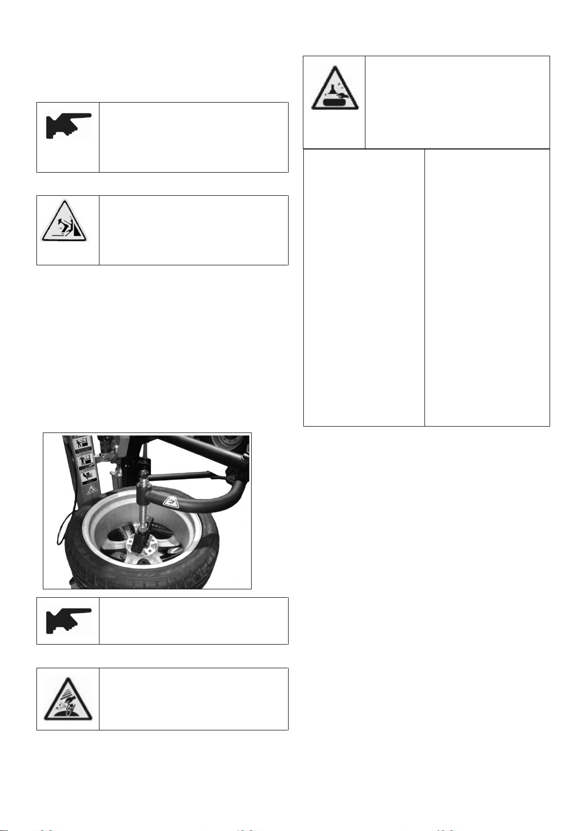
During the process to lock the rim, never
place your hand under the rim. The correct
method to fix is the tire is just at the center
of the turntable.
Outer clamping
Refer to the position of the
clamping jaw on the
turntable(Fig2-1 F and
Fig1-5)to place the tire.
Step down the pedal
(Fig5-1 I)to the middle
position. Place the tire on
the clamping jaw and
press down the rim. Step
the pedal(Fig5-1 I)to the
limit position.
Inner clamping
Refer to the position of the
clamping jaw(Fig2-1 E)
to position the tire to make it
completely closed.
Place the tire on the
clamping jaw and press
down the rim. Step the pedal
Fig5-1 I)to open the jaw to
clamp the rim.
Position the lock press button at the position(Fig4-16 Y)to
release the lock of the tool arm M.
5.2.2 Move the tool arm downwards making the tool head
above the rim. Position the lock button at the position
(Fig4-16 Z)to lock the entire tire demounting assembly.
This kind of lock is the vertical and horizontal lock. The
distance from the tool head to the rim is 2mm(Fig5-3).
Insert the crowbar in between the bead and tool head (Fig5-5)
making bead move above tool head.
Never place your hand on the wheel. When
the column back to its work position, the
hand of the operator will be crashed in
between the tire and rim,
Secure the rim is firmly fixed on the
clamping jaw.

14
Fig 5-3
Necklace, bracelet and loosen cloths or the foreign
objects near the moving pars will cause danger
5.2.3 As shown in the figure, use the helper press
roller to press the tire.
5.2.4 Move the tool head downward to reach out the
tool hook.
5.2.5 until the tool hook deeply into the inside of
the tire
5.2.6 Push upward the tool head handle valve to take
back the tool hook. At this moment, the tool hook
has detached the tire from the rim.
5.2.7 Step down the main shaft rotation switch to
make the turntable carry the tire rotates
clockwise.

15
5.2.7 Use the tire support disk on the helper.
5.2.8 Press down the tool hook handle to extend the tool
hook.
5.2.9 Use your hand to rise up the outside of the tire and
press upward tool hook handle to hook up the tire.
5.2.10Step down the main shaft rotate switch to make the
turntable drive the tire clockwise rotate.
5.3 Mounting tire
5.3.1Place the tire repaired and the new tire on the rim as
shown in the following figure.
5.3.2 Clockwise rotate the turntable to drive the rim.

16
5.3.3 As the figure shown, press the tire press roller and
the tire presser under the edge of the rim.
5.3.4Clockwise rotate the turntable to drive the rim.
The most important is to check the rim and tire
to prevent the explosive during re-inflation
process. Before installation, you should secure:
Tire and tire thread fiber not damaged. If you
find the damage, do not mount the tire;
The rim without dent and warp by visual check.
Note that there is not any small scratch inside
the Alum alloy rim. These are dangerous,
especially while inflation.
Use the special grease to lubricate the bead for fear the bead
to be damaged and convenient to operate.
When lock the rim, do not place the hand under
the tire. The correct operation is to position the
tire at the center of the turntable.
22inch turntable clamping range:10-20inch is the inside
clamping without washer;12-24inch is the outside clamping
While the column is tilting, you should make
sure that nobody is standing behind the column.
If the tire changer handle the same size of the
rim, it is no need to frequently lock or release
the lock of the tool arm. What you need to do is
only to tilt back and forward the column and

17
keep the tool arm at the work position.
Never place your hand on the wheel. The
column back to its work position will crash the
operator ( in between the rim and tool head.)
Move the tire making the bead pass under the tool head. The
buckling part of the bead will lean against the back of the
tool head. Use your hand to press the bead into the groove of
the rim. Step down the pedal(Fig5-1 K)making the turntable
rotate clockwise. Continue this operation until the tire is
completely into the rim.
To prevent the industrial accident, when the
turntable rotates, keep your hand and the other
part of your body far away from the tool arm.
Put in the tube, repeat the above operation
When demount and mount the tire, the turntable
will clockwise rotate. Counterclockwise rotate
on the condition that the machine turns off
causing the wrong operation and must make
correction.
6. Inflation
You should be very carefully when inflate the
tire. Seriously follow the following instruction
due to design of the tire changer does not
consider the prevention the persons around from
the accidental tire burst.
Tire burst will cause the serious injury or death
to the operator. Carefully check whether the
size of the rim and tire is the same. Before
inflation, you should check whether there is
any fault and abrasion on the tire. After each
inflation, you should check the pressure. All
of our tire changers is limited to the max.
inflation air pressure of 3.5 巴equal to
51psi. No matter how, it will not exceed the
pressure value suggested by the manufacturer.
And keep your hand and body far from the
tire.
6.1Use the inflation gauge to inflate the tire. On
the condition of the standard mode, our tire
changers are equipped with the inflation gauge. The
process is as follows:
①Connect the inflation gauge with the core of the
tire.
②Check whether the size of the tire is mating with
the size of the rim.
③Check whether the bead has been fully lubricated.
If necessary, undertake the lubrication.
④Inflation,Check the air pressure of the pressure
gauge.
⑤Continue inflation. Check air pressure while
inflation.

18
Danger of explosive!
When inflate the tire, do not exceed 3.5bar
(51psi); If need relative high air pressure,
detach the tire from the turntable and place
into the special tire cage to inflate, Never
exceed the inflation pressure suggested by the
manufacturer. Keep your hand and the body
behind the tire being inflated. Only can the
person under the professional training inflate
the tire. The other persons should not stand
near the tire changer and operate.
6.2Use the IT system to inflate the tire
When inflate the tubeless tire, it is convenient to use IT
system to inflate.
During this process, the noise can reach
85dB.At this time, we suggest to use the
noise protection.
①Fix the wheel on the turntable and connect the
inflation head with the core of the tire.
②Check whether the size of the tire is mating with
the size of the rim.
③Check whether the bead has been fully lubricated.
If necessary, undertake the lubrication.
④Step down the pedal to the middle position.
⑤Inflation,Check the air pressure of the pressure
gauge. Continue inflation. Check air pressure while
inflation until the pressure reach the pressure
value required.
Danger of explosive!
When inflate the tire, do not exceed 3.5bar
(51psi); If need relative high air pressure,
detach the tire from the turntable and place
into the special tire cage to inflate, Never
exceed the inflation pressure suggested by the
manufacturer. Keep your hand and the body
behind the tire being inflated. Only can the
person under the professional training inflate
the tire. The other persons should not stand
near the tire changer and operate.
7. Helper installation and
operation(helper is optional)
PL330 left helper and AL335 right helper is the
important assist device to the tire changer. You can
attach one or both to the tire changer with the
turntable larger than 20 ″, helping demount and
mount the stiff and run flat tire difficult or
impossible to complete only be human force.
7.1 Left helper installation
Switch off the power supply and air source
before installation!

19
Fig 7-1
Fig 7-2
7.1.1 There is the installation hole prepared at the
back of the base plate of the machine cabinet of each
machine that can handle the tire more than 20″.
Before installation, detach the side panel and then
the T rubber plug.
7.1.2 Open the package box of PL330 helper and then
check whether the spare parts is are intact as per
the packing list Fig 7-2. And then take out the base
frame assembly(Fig7-1)and detach the screw and
washer on it.
7.1.3 Push the base plate of the base assembly into
the machine cabinet from left back, making the
thread hole align to the reinforcement hole. Use
the bolt and washer to fix(Fig7-2).
7.1.4 Place the main frame support(Fig7-3 A)
on the base assembly Fig 7-3. Align and use the screw
unscrewed before Fig(7-3)to fix. Remind not too
tight.
Fig 7-3
Fig 7-4
7.1.5 Use the fix bracket(Fig7-4 A)to connect the
main frame support with the machine cabinet and
insert the screw to fix.
7.1.6 Use the Y Tee to connect the air source
(Fig7-5 A)and the other end is connected with the
helper pressure valve inlet.
7.1.7 Connect the air route. Insert the tire press
roller connect rod(Fig 7-6 A)into the rotating
arm rotating shaft hole(Fig7-6 B). Operate the
handle direction changing valve to make the tip of
the tire press conic roller align with turntable
Table of contents
Popular Tyre Changer manuals by other brands


Hofmann
Hofmann monty 3850 Operation manual

TMG
TMG TMG-TTC26 product manual

Hofmann Megaplan
Hofmann Megaplan Megamount Twister EVO CP Installation, operation and maintenance guide

SICE
SICE S 42 instruction manual

Mondolfo Ferro
Mondolfo Ferro Aquila AS 914 TI Operator's manual

HENNESSY INDUSTRIES
HENNESSY INDUSTRIES Coats 50 manual


