Cormach CM 1200 BB User manual

TYRE CHANGER
CM 1200 BB
USE AND MAINTENANCE
MANUAL
UK


DICHIARAZIONE DI CONFORMITA’
DECLARATION OF CONFORMITY
DECLARATION DE CONFORMITE
KONFORMITÄTSERKLÄRUNG
DECLARACION DE CONFORMIDAD
Cormach S.r.l., Via A. Pignedoli, 2 – 42015 Correggio (RE) – Italy,
Produttore della linea di SMONTAGOMME, mod. CM 1200 BB
Manufacturer of the range of TYRE CHANGER, mod. CM 1200 BB
Fabricant de la gamme de DEMONTE-PNEUS, mod. CM 1200 BB
Hersteller in der Linie der REIFENMONTIERGERAT, mod. CM 1200 BB
Constructor de la gama de DESMONTADORA DE NEUMATICOS, mod. CM 1200 BB
Matricola/Serial Number/Numéro de série/Seriennummer/Matricula _____________________________
Dichiara sotto la propria responsabilità che il prodotto al quale questa dichiarazione si riferisce, è conforme a quanto previsto dalle seguenti
Direttive:
Declare under our own responsibility that the product to which this declaration relates, is in conformity with the following directives:
Déclarons sous notre seule responsabilité que les produits auquel se réfere cette declaration, sont conformes aux directives suivantes:
Erklären in alleiniger Verantwortung, dass das Produkt, auf das sich diese Erklärung bezieht, in Einklang mit den Bestimmungen der folgenden
Richtlinien:
Declara bajo su responsabilidad propria que los productos al que hace referencia esta declaración, cumplen con lo establecido por la siguientes
directivas:
-Direttiva 2006/42/EC (Direttiva Macchine, MD) – 2006/42/EC – 2014/35/UE – 2014/29/EU – 2014/30/UE – 2011/65/EU
-Directive 2006/42/EC (Machinery Directive, MD) – 2006/42/EC – 2014/35/UE – 2014/29/EU – 2014/30/UE – 2011/65/EU
-Directive 2006/42/EC (Directive Machines, MD) – 2006/42/EC – 2014/35/UE – 2014/29/EU – 2014/30/UE – 2011/65/EU
-Richtlinie 2006/42/EC (Maschinenrichtlinie, MD) – 2006/42/EC – 2014/35/UE – 2014/29/EU – 2014/30/UE – 2011/65/EU
-Directiva 2006/42/EC (Directiva Màquinas, MD) – 2006/42/EC – 2014/35/UE – 2014/29/EU – 2014/30/UE – 2011/65/EU
-Norma EN 12100 – EN 60204-1
-Norm EN 12100 – EN 60204-1
-Norme EN 12100 – EN 60204-1
-Die Norm EN 12100 – EN 60204-1
-Norma EN 12100 – EN 60204-1
Correggio, 20.04.2016
IMPORTANTE:
•Eventuali modifiche della macchina, l’inosservanza delle indicazioni contenute nel manuale d’uso e manutenzione o un uso della
macchina diverso da quello previsto dal costruttore, rendono nulla la presente dichiarazione.
•Any changes to the machine, ignoring the instructions contained in the user manual or use of the machine other than that provided by
the manufacturer, will invalidate this declaration.
•Toute modification de la machine, en ignorant les instructions contenues dans le manuel ou l’utilisation de la machine autre que celle
prevue par le fabricant, annulera cette declaration.
•Alle Änderungen an der Maschine, ohne auf die in der Betriebsanleitung und Wartung oder dem Einsatz des anderen als die vom
Hersteller vorgesehenen Maschine enthaltenen Anweisungen, machen diese Erklärung ungültig
•Cualquier modificación de la maquina, el incumplimiento de la instrucciones contenidas en el manual o la utilización de la maquina
distinta a la prevista por el fabricante, anulan esta declaración.
Il modello della presente dichiarazione è conforme a quanto previsto dalla Norma EN ISO/IEC 17050-1 – EN ISO/IEC 17050-2


User Manual CM 1200 BB 3
CONTENTS
INTRODUCTION........................................................................................................4
TRANSPORT, STORAGE AND HANDLING.............................................................4
UNPACKING/ASSEMBLY ..........................................................................................5
HOISTING/HANDLING.............................................................................................5
INSTALLATION CLEARANCES.................................................................................6
ELECTRICAL AND PNEUMATIC CONNECTIONS..................................................7
SAFETY REGULATIONS............................................................................................8
DESCRIPTION CM 1200 BB......................................................................................9
TECHNICAL DATA ....................................................................................................10
OPTIONAL ACCESSORIES SUPPLIED ON REQUEST ...........................................11
RIM CENTRING/ CLAMPING ACCESSORIES AND THEIR USE............................12
SPECIFIED CONDITIONS OF USE ..........................................................................12
MAIN OPERATING PARTS........................................................................................20
PRACTICAL HINTS, ADVICE AND IMPORTANT INFORMATION .........................24
TYRE DEMOUNTING................................................................................................25
TYRE MOUNTING .....................................................................................................31
APPROVED M/D PROCEDURE FOR UHP AND RUN FLAT TYRES ......................34
“EXTRAORDINARY” MOUNTING PROCEDURE ...................................................34
CORRECT PROCEDURE FOR DEMOUNTING/MOUNTING RUN
FLAT TYRES FITTED WITH VALVE SENSOR ..................................................35
CORRECT PROCEDURE FOR DEMOUNTING/MOUNTING RUN
FLAT TYRES WITH STRAP-ON SENSOR .........................................................36
INFLATION.................................................................................................................36
MAINTENANCE.........................................................................................................38
ENVIRONMENTAL INFORMATION.........................................................................39
INFORMATION AND WARNINGS ABOUT OIL .......................................................39
RECOMMENDED FIRE-EXTINGUISHING DEVICES.............................................41
TROUBLE SHOOTING ..............................................................................................42
WIRING DIAGRAM ....................................................................................................43
PNEUMATIC SYSTEM DIAGRAM.............................................................................43

4User manual CM 1200 BB
INTRODUCTION
The purpose of this manual is to furnish the
owner and operator with a set of practical, safe
instructions on the use and maintenance of the
CM 1200 BB tyre changer.
Follow all the instructions carefully and the ma-
chine will give you the efficient and long-lasting
service that has always characterised CORMACH
products, making your work considerably easier.
The following points define the levels of danger
regarding the machine, associated with the war-
ning captions found in this manual:
DANGER
Refers to immediate danger with the risk of
serious injury or even death.
WARNING
Dangers or unsafe procedures that can cause
serious injury or even death.
CAUTION
Dangers or unsafe procedures that can cause
minor injuries or damage to property.
Read these instructions carefully before powe-
ring up the machine. Keep this manual and all
illustrative material supplied with the machine
in a folder near the tyre changer, where it is rea-
dily accessible for consultation by the machine
operators.
The technical documentation supplied is consi-
dered an integral part of the machine and must
always accompany the equipment if it is sold or
transferred to a new owner.
The manual is only to be considered valid for the
machine model and serial number indicated on
the nameplate applied to it.
WARNING
Observe the contents of this manual: the ma-
nufacturer declines all liability in the case of
uses of the machine not specifically described
and authorised in this manual.
WARNING
This machine must be used only by qualified
and authorised personnel able to understand
the written instructions provided by the manu-
facturer of the machine, the tyres and the rims.
He must be suitably trainedand conversant with
the safety procedures. Use of the machine by
unskilled staff may con
stitute a serious risk for the operator and for
the final user of the product processed (the
wheel rim and tyre mounting).
NB:
Someofthe illustrationsin thismanualhavebeen
taken from photographs of prototypes: standard
productionmachines may vary in some respects.
These instructions are intended for people with
basic mechanical skills. We have therefore omit-
ted detailed descriptions of procedures such as
how to loosen or tighten the fixing devices on the
machine. Do not attempt to perform operations
unless properly qualified and with suitable ex-
perience. In case of need, contact an authorised
Service Centre for assistance.
TRANSPORT, STORAGE AND
HANDLING
Conditions for transporting the
machine
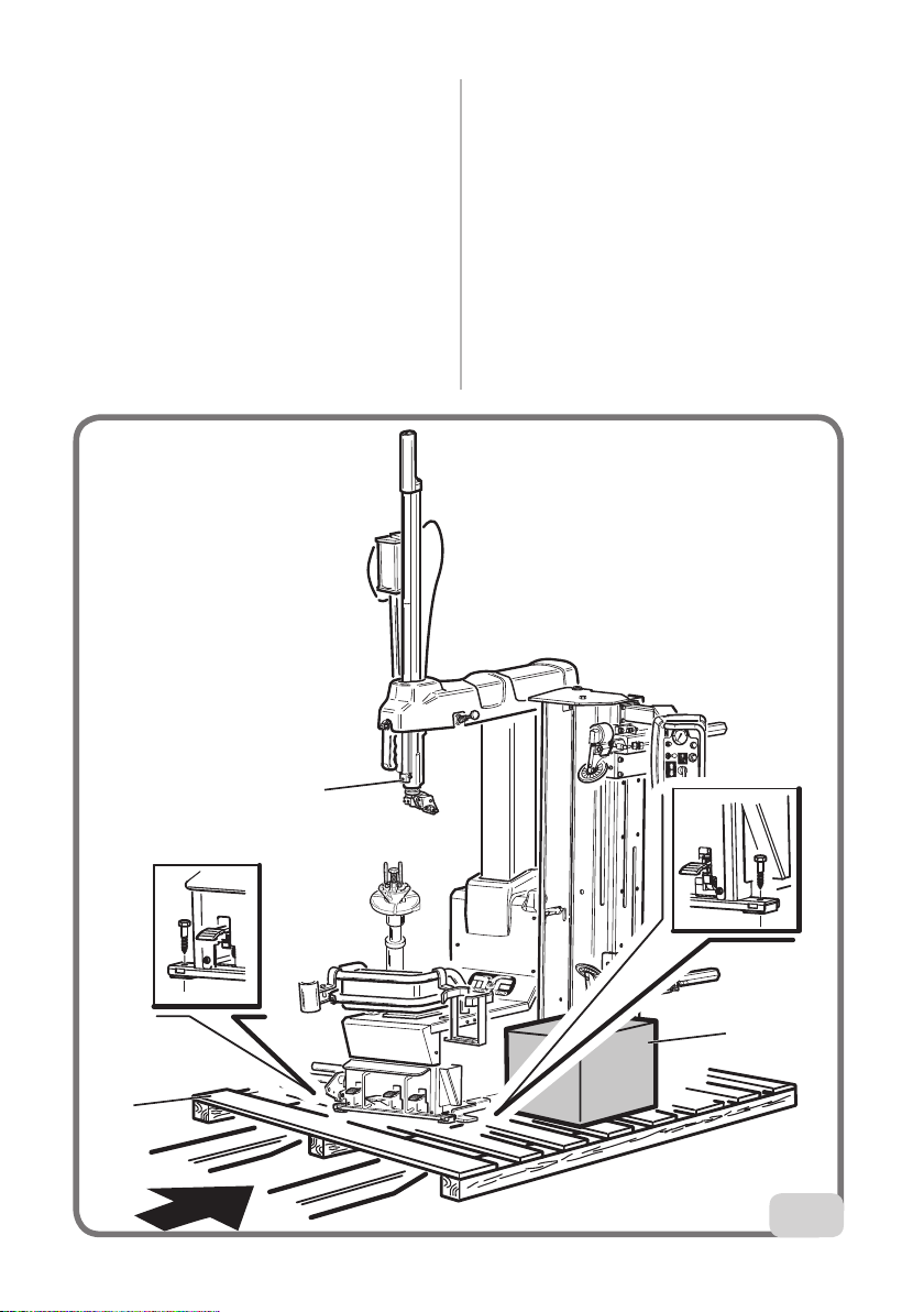
The tyre changer must be transported in its
original packaging and stowed in the position
shown on the packaging itself.
- Packaging dimensions:
• width ...................................................1543mm
• depth ..................................................1140mm
• height ..................................................1900mm
- Weight of wooden packaging:
• .................................................................. 380kg
Ambient conditions for machine
transport and storage
Temperature: -25° - +55°C.
WARNING
Do not stack other goods on top of the packa-
ging, to avoid damaging it.
Handling
To move the packaging, insert the tines of a

User Manual CM 1200 BB 5
fork-lift truck into the slots on the base of the
packaging itself (pallet) (1-fig.1).
Before moving the machine, refer to the HOI-
STING/HANDLING chapter.
UNPACKING/ASSEMBLY
WARNING
Take the utmost care when unpacking, assem-
bling, hoisting and installing the machine as
described below.
Keep the original packaging in good condition
for any future transportation.
Failureto complywith theseinstructionsmay da-
mage the machine and risk the operator’s safety.
Free the machine from the upper part of the
packaging.
The machine is fully assembled, comprising two
main groups, 2- the machine, 3- the accessories
(fig.1).
Identify the points 4 and 5 at which the machine
is anchored to the pallet and proceed to remove
fixing devices (fig.1).
HOISTING/HANDLING
In order to remove the machine from the pallet,
2
4
1
3
5
1

6User manual CM 1200 BB
hook it up as shown in fig.2.
This hoisting point must be used whenever you
need to change the installation position of the
machine. Do not attempt to move the machine
untilithas beendisconnected fromtheelectricity
and compressed air supply systems.
2
INSTALLATION CLEARANCES
WARNING
The installation site must be chosen in strict
compliance with the relevant regulations re-
garding Safety in the workplace.
IMPORTANT: for correct, safe use of the
equipment, we recommend a lighting level of
at least 300 lux in the place of use.
CAUTION
If the machine is installed outdoors, it must be
properly sheltered under a roof.
WARNING
The floor must be able to withstand a load equal
to the sum of the weight of the equipment itself
and the maximum payload, bearing in mind
the support surface area and eventual anchor
fixtures used.
Install the tyre changer in the chosen work po-
sition, complying with the minimum clearances
shown in fig.3.
The machine must be placed on a horizontal
surface,preferablyconcrete ortiled.Do notinstall
on unstable or damaged surfaces.
The surface on which the machine rests must
withstandtheloadstransmittedduring operation.
The surface must have a load-carrying capacity
of at least 500kg/m2.
900
1200
500
3
Ambient working conditions
- Relative humidity 30% - 95% without conden-
sation.
- Temperature 0°C - 50°C.
WARNING
Use of the machine in a potentially explosive
atmosphere is not permitted.

User Manual CM 1200 BB 7
ELECTRICAL AND
PNEUMATIC CONNECTIONS
WARNING
Any connections to the workshop electrical pa-
nel are the customer’s responsibility, and must
be made by staff qualified in accordance with
the relevant legal requirements.
Before connecting the air supply system, make
sure the machine is set up as in fig.4:
pedal 13 fully up, column forward.
4
- The electrical supply must be suitably sized
in relation to:
• the machine input power as specified on the
corresponding machine data plate;
• the distance between the machine and the
power supply hook-up point, so that voltage
drops under full load do not exceed 4% (10%
during start-up) compared with the rated
voltage specified on the data plate.
- The user must:
• fit a plug on the power supply cable in com-
pliance with the relevant safety standards;
• connect the machine to its own electrical
connection - A fig.5 - and fit a residual current
circuit breaker with 30 mA residual current;
A
B
5
• fit fuses on the power supply line, rated
as indicated on the general wiring diagram
contained in this manual;
• installan efficient grounding circuit to protect
the workshop electrical system.
- In order to prevent the machine from being
usedbyunauthorisedpersonnel,it isadvisable
to disconnect the power supply plug when the
machine remains idle (switched off) for long
periods.
- Ifthemachine isconnecteddirectly tothepower
supply by means of the main electrical board
without a separate plug, install a key-operated
switch (or at least a switch that can be locked)
torestrict machineuse toauthorised personnel
only.
WARNING
A good grounding connection is essential for
correct operation of the machine.
NEVER connect the earth wire to a gas or water
pipe, telephone line or any other unsuitable
objects.

8User manual CM 1200 BB
Check that the pressure and flow-rate provided
by the compressed air system are compatible
with those required for proper operation of the
machine - see the "Technical data" chapter. For
correct machine operation the compressed air
supply line must provide a pressure range from
no less than 8 bar to no more than 16 bar.
Connect the compressed air system by means
of a supply pipe connected to the intake of
the air treatment unit on the REAR SIDE of the
machine base.
Check that there is air lubrication oil in the
Lubricating unit; refill if there is little or no oil.
Use SAE20 oil.
The customer must provide an air shutoff valve
upstream of the air treatment and regulating
device supplied with the machine.
1
6
WARNING
Connection 1 should be considered as an
emergency valve to disconnect the machine
from the air line (fig.6).
SAFETY REGULATIONS
The equipment is intended for professional
use only.
WARNING
Only one operator may work on the equipment
at a time.
WARNING
Failure to comply with the instructions and
danger warnings may seriously injure operators
and any other person near the machine. Do not
operate the machine until you have read and
understood all the danger, warning and caution
notices in this manual.
Thismachine mustbe used onlyby qualifiedand
authorised personnel able to understand the
written instructions provided by the manufactu-
rer. He must be suitably trained and conversant
with the safety procedures. Operators must not
use the machine under the influence of alcohol
or drugs which may affect their capacity.
The operator must, in all cases:
- be able to read and understand all the infor-
mation in this manual;
- have a thorough knowledge of the capabilities
of this machine;
- keep unauthorised persons well clear of the
area of operation;
- make sure the machine has been installed in
compliance with all relevant regulations and
legislation;
- make sure that all machine operators are suita-
bly trained, that they are capable of using the
equipment correctly and safely, and that they
are adequately supervised;
- never leave nuts, bolts, tools or any other
equipment on the tyre changer as they may
become entrapped between moving parts;
- not touch power lines or the inside of electric
motors or any other electrical equipment be-
fore making sure the power supply has been
disconnected;
- read this manual carefully and learn how to use
the machine correctly and safely;
- alwayskeep this user andmaintenancemanual
in an easily accessible place and consult it
whenever necessary.

User Manual CM 1200 BB 9
WARNING
Do not remove or deface the Danger, Warning
or Instruction decals. Replace any missing or
illegible decals. If one or more decals have
been detached or damaged, replacements can
be obtained from your nearest dealer.
- Whenusingandservicingthe machine,observe
thestandardisedindustrialaccidentprevention
regulations for high voltages.
- Any unauthorised alterations or changes made
to the machine shall automatically release the
manufacturer from any liability for damage or
accidents attributable to such modifications.
Specifically, tampering with or removing the
safety devices is a breach of the regulations
for Safety in the workplace.
- The user must wear personal protective
equipment such as gloves, safety footwear and
goggles.
WARNING
When operating or servicing the equipment, tie
back long hair and do not wear loose-fitting
clothes, ties, necklaces, rings or wristwatches
whichcould becomeentrapped by movingparts.
DESCRIPTION CM 1200 BB
TheCM 1200 BBis a universalelectro-pneumatic
tyre changer that works on integral wheels with
dropcentre featuring weights and dimensionsas
described in the technical data section.
It is designed to work effectively on:
- conventional wheels;
- reverse rim wheels or wheels without central
hole - (use optional kit);
- run-flat tyres with reinforced sides*.
* WARNING: there are specifically studied pro-
cedures for these types of wheels.
NB: It may be difcult and sometimes impossible to clamp
and/or disassemble wheels of vintage cars (cars out of pro-
duction for over 30 years), some types of rally wheels and
non-standardised street wheels.
The machine is solidly constructed. It operates
with the wheel in a horizontal position for both
bead breaking and demounting/mounting
operations.
All machine movements are controlled by the
operator by means of a pedal in a pedal board
and manual controls on the console.
The CM 1200 BB can be used to easily break,
disassemble and assemble any type of the
above tyres.
In any stage, the CM 1200 BB operates with a
clamped and perfectly centred horizontal wheel
on the turntable.
Wheel loading and unloading operations are
simplified by an ergonomic lifter (optional kit)
which reduces the operator effort required.
Its absolutely innovative operating principle
comprises:
- a wheel positioning system that makes use of
the wheel inner side and the machine axial
mounting turntable as references (an optional
reverse rim kit is supplied for rims with drop
centres on the inner side);
- an efficient manual wheel clamping system,
which makes use of the rim central hole by
means of a handle and cones (an optional
clampingkit is suppliedforrims with nocentral
hole);
- a pneumatic bead breaking unit consisting
of two bead breaker disc holders. Its vertical
pneumatic movement is independent and
activated from the console; the disc horizontal
positioning is manual, mechanically activated
fromthe consoleand itallows thesimultaneous
positioning of the bead breaker discs. Bead
breaking is ensured by the disc movement,
with a controlled penetration commanded by
a dead-man's switch;
- ahead positionedon amobilecolumn withrear
opening. It consists of a fixed load-bearing core
that allows the mounting phase with the use of
the bead lifter lever;
- a pedal-controlled pneumatic wheel lift which
allows you to load and unload the wheel to and
from the working position.
With the CM 1200 BB the following objectives
have also been reached:
- minimised physical effort on the part of the
operator;
- no risk of damage to rim and tyre.

10 User manual CM 1200 BB
Eachmachinecarries aplatewith itsidentification
data and some technical data.
Aswell as the manufacturer’sdetails, it indicates:
Mod. - Machine model; V- power supply voltage in Volts;
A- Input voltage in Amperes; kW - Absorbed power in
kW; Hz - Frequency in Hz; Ph - Number of phases;
bar - Operating pressure in bar; Serial No. - Machine
serial number; ISO 9001 - Certication of the company's
Quality System; EC - EC marking.
WARNING
It is forbidden to modify or remove the data
on the plate.
TECHNICAL DATA
- Overall dimensions (see fig.7):
• Length...............................................1235 min–
1784 max
• Width ................................................928 min –
2018 max
• Height...............................................1170min –
2184 max
- Wheel dimension range:
• Rim diameter...........................from 10” to 28”
• Maximum tyre diameter ....... 1080 mm (42”)
• Max tyre width .............................................15”
(from wheel supporting base)
- Turntable:
• Resting side: ........................................flanged
• Centring:.............................................. on cone
• Clamping: ........................ mechanical-manual
• Drive system:......................................2-speed
motor-inverter unit
• Rotation torque: .................................1200Nm
• Rotation speed:..................................6-15rpm
- Bead breaking unit:
• Tool: ...........................................................disc
• Positioning in relation to rim: .............manual
with mechanical clamping
• Penetration: ..........................................guided
• Maximum bead breaking range.....A=670mm
(see diagram page 13)
• Bead breaker stroke ......................B=540mm
(see diagram page 13)
• Bead breaking cylinder force: ............... 550N
- Wheel lifter:
• Lifting operation:.............................automatic
Manual tilting
• Activation: .......................................pneumatic
• Lifting capacity: ........................................ 85kg
- Power supply:
• Electric, 1Ph .....................................230V-0.75
kW 50Hz/60 Hz
• Electric, 1Ph (alternate)..................110V-0.75
kW 50Hz/60 Hz
• Pneumatic operating pressure: ........... 10 bar
- Weight:........................................................380kg
- Weight of electrical/
electronic components:...........................11.5kg
- Noise level:
• A-weighted sound pressure level (LpA) at the
working position..............................< 70 dB (A)

User Manual CM 1200 BB 11
2224 max
1784 max
2018 max
7
The noise levels indicated correspond to emis-
sion levels and do not necessarily represent safe
operatinglevels. Although there is arelationship
between emission levels and exposure levels,
this cannot be used reliably to establish whether
or not further precautions are necessary. The
factors which determine the level of exposure
to which the operator is subject to include the
duration of the exposure, the characteristics of
the workplace, other sources of noise, etc. The
permitted exposure levels may also vary accor-
dingto thecountry.However,this informationwill
enable machine users to make a more accurate
assessment of hazard and risks.
OPTIONAL ACCESSORIES
SUPPLIED ON REQUEST
For codes not included here, see the “ORIGINAL
ACCESSORIESFORCM 1200BBTYRECHANGER”
handbook supplied with the machine.
8-11100128 ................................. Bead presser kit
8-11100154 ................................. Kit for truck rims
8-11100155 ................................. “Wire Wheel” kit
8-11100156 ............................................Flange for
............................................. reverse rim well wheels
8-11100157 ..... Extension kit for flange for wheels
..............................with blind and reverse rim wells
8-11100158 ...........Universal flange for blind rims
8-11100159 ................................Accessory holder
8-11100160 ....................Quick bead insertion kit:
.....................................................................F.S. system
8-11100154
8-11100155
8-11100156
8-11100157

12 User manual CM 1200 BB
8-11100160
8-11100158
8-11100159
RIM CENTRING/
CLAMPING ACCESSORIES
AND THEIR USE
For the diagram concerning optimal use of the
centring and clamping accessories depending on
rim type, see fig.8 and subsequent.
SPECIFIED CONDITIONS OF
USE
The CM 1200 BB tyre changers have been
designed exclusively for assembling and disas-
sembling tyres, using the tools the machines
are equipped with, following the instructions
in this manual.
WARNING
Any other operations carried out onthe machine
are considered as improper use and shall be
construed as negligence.
These machines are equipped with an inflation
system independent from any other function
described above. Take great care when using it
(read the INFLATION chapter).
WARNING
You are strongly advised not to use equipmentor
toolsnot originally manufacturedbyCORMACH.
The operator's position during the different
operating stages is shown in fig.9.
9
A
WARNING
Keep hands well away from machine moving parts.
WARNING
To stop the machine in an emergency:
-disconnect the power supply plug;
- isolate the compressed air supply network
by disconnecting the (quick-coupling) shutoff
valve (fig.6).

User Manual CM 1200 BB 13
8
Rim without central hole
E
Rims for vans
D
Reverse rims
C
Standard rim
A
Rim with embedded hole
B
USE OF CENTRING AND CLAMPING
ACCESSORIES ACCORDING TO RIM TYPES
Rim with central hole
F

14 User manual CM 1200 BB
8a
M9
M2 M15
M4
M10
M13 M14
M7 M11
*Optional accessories
supplied on request
*
*
** *

User Manual CM 1200 BB 15
8b
M13M14
M11
M7
M2
M9
A

16 User manual CM 1200 BB
8c
M6
M5
M11
M7
M9
B

User Manual CM 1200 BB 17
8d
C
M11
8e
M10
M2 M15
M9
D

18 User manual CM 1200 BB
8f
E
Table of contents
Other Cormach Tyre Changer manuals