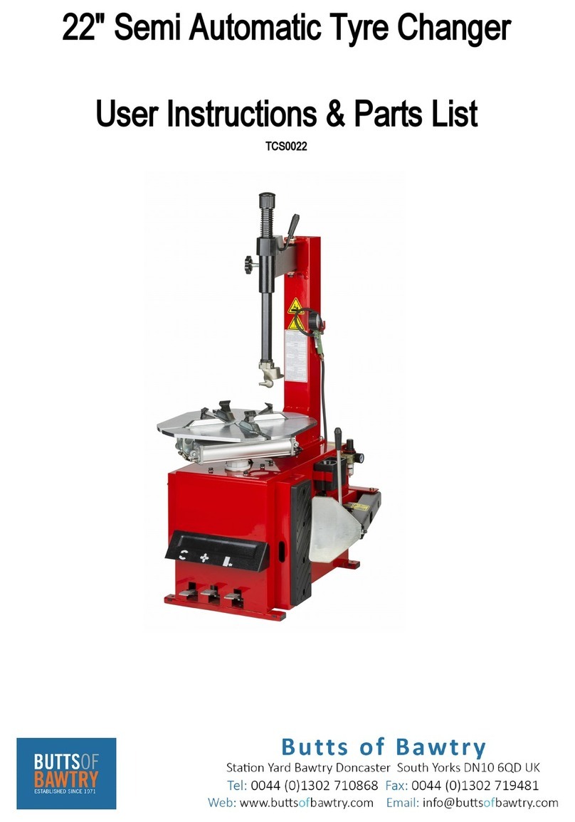
Coseng C211 C User manual

C211 C
Swing Arm Tire Changer
OperaƟon Manual
Installation, Operation, Maintance
You will need the manual for the in-
formation of the machine, such as
safety warnings and precautions, as-
sembly, operating, maintenance and
parts lists/assembly diagrams. Keep
your invoice with this manual for fu-
ture reference. Manufacturer shall
not be liable for any injury to persons
on damage to things caused by fail-
ure to comply with these regulations
and can cancel warranty coverage.

- 1 -
TIRE CHANGER
INSTRUCTION MANUAL
INDEX
INDEX PAGE
1. TechnicalData -----------------------------------------------------------------
2. General safety warnings and precautions ---------------------------------
3. Specific Product Warnings And Precautions ---------------------------------
4. Assembly Instruction ------------------------------------------------------------
4-1 Transport
4-2 Unpacking
4-3 Product Description
4-4 Workplace Requirements
4-5 Assembly Procedure
4-6 Pneumatic Link Up
4-7 Electric Link Up
5. Warning Label -----------------------------------------------------------------------------
6. Operating Instructions ------------------------------------------------------------------
6-1 To Perform Preliminary Operating Texts
6-2 To Break The Tire Bead
6-3 Demounting The Tire From The Wheel
6-4 Mounting The Tire Onto The Wheel Rim
6-5 Inflating The Tire
7. FRL Instruction -------------------------------------------------------------------
8. Routine Maintenance -------------------------------------------------------------------
9. Trouble Shooting Guide -----------------------------------------------------------------
10. Mounting Head’s Angle Adjusting -----------------------------------------------------
11. Exploded Drawings And Spare Parts List ----------------------------------
2
2
3
4
6
7
10
11
12
14
15

- 2 -
1. TECHNICAL DATA
Model DESCRIPTION
□A □B □C
Electric Requirements See the manufacturer’s serial plate
Max. Wheel Diameter 39″(990mm) 40″(1016mm) 47″(1193mm)
Max. Wheel Width 13″(330mm) 14″(355mm) 15″(381mm)
Outside Clamping – Rim Sizes 10″~18″10″~21″10″~24″
Inside Clamping – Rim Sizes 12″~20″12″~23″12″~26″
Max. Bead Breaker Opening 13″(330mm) 14″(355mm) 15″(381mm)
Max. Inflation Pressure 116PSI (8 bar)
Bead Breaker Force 5500Lbs.(2500kgs)
Max. Rotating Torque (Turntable) 795 ft·lbs (1078N·m)
Noise Level <70dB
Overall Dimensions (L×W×H) 38.2″×30.1″×37″
(97cm×77cm×94cm) 38.2″×30.1″×37″
(97cm×77cm×100cm) 47.2″×29.9″×41.7″
(115cm×77cm×100cm)
Shipping Weight 217kg 222kg 245kg
Voltage 0.9…1.1 of nominal voltage
Frequency 0.98…1.02 of nominal frequency
Ambient temperature 5~40℃
Humidity 30~95%
Installation altitude NOT exceed 1000m
Transport / storage temperature -25~55℃
2.GENERAL SAFETY WARNINGS AND PRECAUTIONS
You will need the manual for the information of the machine, such as safety warnings and
precautions, assembly, operating, maintenance and parts lists/assembly diagrams. Keep
your invoice with this manual for future reference. Manufacturer shall not be liable for any
injury to persons on damage to things caused by failure to comply with these regulations
and can cancel warranty coverage.
1) BEFORE BEGINNING ANY KIND OF WORK ON OR WITH THIS MACHINE,
CAREFULLY READ AND UNDERSTAND THE CONTENTS OF THESE OPERATING
INSTRUCTIONS.
2) WORK ON THE ELECTRIC SYSTEM, EVEN IF MINOR, MUST BE DONE
EXCLUSIVELY BY PROFESSIONALLY QUALIFIED PERSONNEL.
3) KEEP WORK AREA CLEAN AND DRY. Cluttered, damp or wet work areas invite
injuries.
4) KEEP CHILDEN AWAY FROM WORK AREA. Do not allow children to handle this
machine.

- 3 -
5) STORE IDLE EQUIPMENT. When not in use, tools and equipments should be stored in
a dry location to inhibit rust. If the machine has to be stored for a long time, disconnect it
from all power sources.
6) DRESS SAFELY. Do not wear loose clothing or jewelry as they can become caught in
moving parts. Wear a protective hair covering to prevent long hair from becoming caught
in moving parts.
7) STAY ALERT. Watch what you are doing at all times. Use common sense. Do not use
this tool when you are tired or distracted from the job at hand.
8) CHECK FOR DAMAGED PARTS. Before operation, carefully check that this tool will
operate properly and perform its intended function. Check for damaged parts and any
other conditions that may affect the operation of this machine. Replace or repair
damaged or worn parts immediately.
9) REPLACEMENT PARTS AND ACCESSORIES. When servicing use only identical
replacement parts. Only use accessories intended for use with this machine. Approved
accessories are available from DISTRIBUTOR.
10)MAITAIN THE MACHINE WITH CARE. Keep the machine clean and dry for better and
safer performance.
11)MAINTENANCE. Service and maintenance should be performed regularly by qualified
technicians.
12)USE THE RIGHT PRODUCT FOR THE RIGHT JOB. There are certain applications for
which this product was designed. Do not use this product for a purpose for which it was
not intended.
13)THE HEIGHT OF THE SOCKET SHOULD BE POSITIONED AT A HEIGHT OF
0.6~1.7m.
14)THE PLUG/SOCKET SHOULD BE POSITIONED THAT IT CAN BE UNDER THE
IMMEDIATE SUPERVISION.
3.SPECIFIC PRODUCT WARNINGS AND PRECAUTIONS
1) BEFORE PERFORMING ANY SERVICES OR MAINTENANCE, ALWAYS
DISCONNECT THE MACHINE FROM ITS AIR SUPPLY SOURCE. PUMP THE BEAD
BREAKER PEDAL SEVERAL TIMES TO EVACUATE ALL COMPRESSED AIR FROM
THE MACHINE, AND DISCONNECT THE UNIT FROM ITS ELECTRICAL SUPPLY
SOURCE.
2) USE CLEAN, DRY, REGULATED COMPRESSED AIR AT UP TO 8 BAR (116 PSI). Do
not exceed the recommended maximum of 8bar.
3) If an automatic oilier is not used, add two drops of oil into the Quick Connector of the
Pressure Regulator.
4) DO NOT INFLATE A TIRE ABOVE OR BELOW THE AIR PRESSURE
RECOMMENDED BY THE TIRE MANUFACTURER.
5) ALWAYS DISPOSE OF OLD TIRES ACCORDING TO CORRELATED LAWS.
6) TO AVOID PERSONAL INJURY AND/DR MACHINE DAMAGE, ALWAYS MAKE SURE
THE TIRE RIM IS FIRMLY SECURED ON THE TIRE CHANGER WITH THE JAWS.
7) NEVER PLACE YOUR HANDS BETWEEN THE VEHICLE WHEEL RIM AND THE
JAWS DURING THE LOCKING/CLAMPING STAGE.
8) THE MACHINE MUST BE CONNECTED TO A POWER SUPPLY LINE CIRCUIT
BRACKET SET FOR 30mA.

- 4 -
4.ASSEMBLY INSTRUCTION
Fig.1
4-1 Transport
When transporting the machine it must be handle with a forklift truck with the forks
Positioned as show as in the Fig.1.
4-2 Unpacking
When unpacking, check to make sure all parts shown on the spare parts List/Assembly.
Diagrams are included. If any parts are missing or broken, please call the manufacturer or
the dealer as soon as possible.
4-3 Production Description
Fig.2
1 BEAD BREAKER PEDAL 2 JAW CLAMP PEDAL
3 REVERSE PEDAL 4 TURNTABLE
5 JAW 6 MOUNTING HEAD
7 TOOLS SHAFT 8 SWINGING ARM
9 BLOCK SUPPORT 10 COLUMN
11 PRESSURE REGULATOR 12 PADDLE
13 BUFFER 14 BEAD LIFTING LEVER

- 5 -
4-4 Workplace Requirements
The machine’s workplace(not include assistant arm) requires 1400(width)×1685(depth)
with at least 500 mm of clear space from each wall. Place the tire changer on a firm,
smooth and unbroken floor. Drill four holes in the floor corresponding to the holes pre-drilled
in the base of the machine. Holes should be 80mm deep. Its diameter is 10mm. Then insert
the expansion
Plugs and lighten with the 10mm spanner.
Fig.3
4-5 Assembly Procedure
1) Temporarily remove the four mounting bolts, washers, and Nuts located at the top / rear
of the body assembly.
2) With assistance, set the column on the body assembly, and align the four mounting
holes in which the bolts, washers, and nuts were moved.
3) Firmly wrench tightens the column with the four mounting bolt, washers, and nuts
mentioned in step 1 above.
4-6 Pneumatic Link Up
1) Push the clamping pedal down completely to ensure that the clamping jaws do not open
unexpectedly.
2) Connect the air hose to the union on bottom of the vertical column, which is as a tanker.
3) Connect the inflation gun, if it is to be installed, to its connector.
4) Connect the tire changer to a compressed air network. (Suggested working pressure is
8 bar) using the connector which is on the air-water separator located right side of the
base assembly.
4-7 Electric Link up
1) Before making any electric link up, check to be certain that the main voltage
corresponds to what is stamped on the voltage tag.
2) It is absolutely essential that the system is equipped with a good grounding circuit.
3) The machine must be connected to a power supply line circuit bracket set for 30mA.

- 6 -
5. WARNING LABEL
CJ001: Unplug the power supply cable before carrying out maintenance work on the
machine.
CJ002: Danger: Electric voltage present.
CJ003: When clamping a tire, never have your hands under the tire.
CJ004: Danger: Compressed air cylinder inside.
CJ005: Do not place your hands on the wheel; when moving the post to its working
position your hands could be crushed between the rim and the mounting head.
CJ006: Bead breaking with the table top slide grippers open can crush the operator’s
hands. During bead breaking NEVER touch walls of the tire with your hands.
CJ007: Bead breaking must be done with the utmost care and attention. When the bead
breaker pedal is operated the bead beaker arm moves quickly and powerfully.
Anything within its range of action can be in danger of being crushed.
CJ008: Important instruction of safe.

- 7 -
6.OPERATING INSTRUCTION
6-1 To Preliminary Operating Tests
1) Connect the tire changer to its air and electrical supply sources, and allow adequate
time for the compressed air system to reach the recommended 110-PSI.
2) Depress the Reverse Pedal (3,Fig2) down, the turntable should turn in a clockwise
direction. Pull the pedal up and the turntable should turn anticlockwise.
3) Press the bead breaker pedal (1,Fig2)to activate the paddle. When the pedal is
released. The pedal should return to its original position.
4) Press the jaw clamp pedal (2,Fig.2) once to open the four jaws. Press the pedal again
to close the jaws.
5) Press the trigger on the air gauge to release air from the nozzle.
Notice: Inflation gun is tire changer’s standard accessory. It is not included when IT,
IP or IE installed.
6-2 To Break Tire Bead
1) CAUTION: Before carrying out this procedure, deflate the tire fully, and remove all the
wheel weights.
2) Close the turntable clumping jaws completely.
3) Open the bead breaker arm by hand by pushing it towards the outside. Place the wheel
up against the Rubber Buffer. Bring the Paddle against the bead about 10mm from the
edge of the rim. (see Fig.5 )
4) Depress the bead breaker pedal fully to activate the paddle. Release pressure on the
bead breaker pedal. When the blade has reached the end of its travel and / or when the
tire bead is broken.
5) Rotate the tire slightly, and repeat the procedure around the entire circumference of the
wheel rim until the bead is completely detached from the rim. (Fig.5)
6) Repeat the above steps for the other side of the wheel / tire.
Fig.5
6-3 To Remove The Tire From The Wheel
1) CAUTION: Before carrying out this procedure, deflate the tire fully, and remove all the
wheel weights.
2) Spread tire grease (or a similar lubricant) liberally on the complete circumference of the
broken tire bead.
NOTE: Failure to lubricate the tire bead may cause serious damage to the bead.
3) Place the wheel / tire evenly on the turntable.(4,Fig.2)
4) To lock the wheel on the turntable, proceed as follows according to the wheel size:
Outside Clamping:
Position the four jaws (5,Fig.2) according to the reference mark located on the turntable by
depressing the jaw clamp pedal (2,Fig.2) halfway down.

- 8 -
Place the wheel on the four jaws and, while keeping the wheel rim pressed down,
depress the jaw clamp pedal as far as it will go.
Check to make sure the wheel firmly secured by the jaws.
Inside Clamping:
Position the four jaws so that they are completely closed.
Place the wheel on the four jaws and depress the jaw clamp pedal to open the jaws,
thereby locking the wheel rim in place.
Check to make sure the wheel is firmly secured by the jaws.
5) Lower the tools shaft (7,Fig.2) until the mounting head (6,Fig.2) rests next to the wheel
rim and on top of the tire. Then, lock the tools shaft in position, using the block support.
6) Insert the lever between the tire bead and the front section of the mounting head.
(Fig.6)
Fig.6
7) Move the tire bead over the mounting head by pulling upward on the reverse
pedal.(3,Fig.2)
8) NOTE: To avoid damaging the inner tube (if there is one), it is recommended to perform
this step with the inner tube valve stem positioned about 1” to the right of the mounting
head.
9) With the lever (14,Fig.2) held in position, rotate the turntable in a clockwise direction by
fully depressing the reverse pedal. Continue until the tire is completely separated from
the wheel rim.
10) Remove the inner tube (if there is one), and repeat the above steps for the other side of
the wheel / tire.
6-4 To Mount The Tire Onto The Wheel Rim
1) CAUTION: Before carrying out this procedure, deflate the tire fully, and remove all the
wheel weights.
2) Spread tire grease (or a similar lubricant) liberally on the complete circumference of the
tire bead to avoid damage to the tire bead to avoid damage to the tire and to facilitate
the mounting procedure.
3) Lock the wheel rim, using the inner part of the jaws.(5,Fig.2)
4) NOTE: When you are working with wheel rims of the same size, it is not always
necessary to lock and unlock the tools shaft. Instead, move the swinging arm (8,Fig.2)
sideways with the tools shaft locked.(7,Fig.2)

- 9 -
Fig.7
5) Move the tire so that the bead passes below the front section of the mounting head and
is brought up against the edge of the rear section of the mounting head. (Fig.7)
6) Keep the tire bead pressed down into the wheel rim channel with your hands. Then,
depress the reverse pedal to rotate the turntable clockwise. Continue this process
throughout the entire circumference of the wheel and tire.
7) Insert the inner tube (if there is one).
8) Repeat the steps above the mount the other side of the tire.
6-5 To Inflate The Tire
1) CAUTION: A burst tire can cause serious injury or even death to the operator. Always
make sure the wheel rim and the tire are of the same size. Check the condition of the
tire, and make sure it has no defects before beginning the inflation process. Keep your
hands and body as far away from the tire as possible. Inflate the tire with brief jets of air,
checking the air pressure frequently.
Never inflate a tire above and or below the air pressure recommended by the tire
manufacturer.
2) To inflate the tire, attach the air gauge nozzle to the tire valve stem with the locking lever
in the “UP” position. Check the condition of the tire, and make sure the nozzle is
pressed down completely over the threads of the valve stem.
3) When the air gauge nozzle is firmly in place, press the locking lever down to lock onto
the valve stem.
4) Remember to inflate the tire with brief jets of air, checking the air pressure frequently.
Once the proper air pressure has been reached, disconnect the nozzle from the valve
stem and screw a valve cap onto the stem. (Fig.8)
Fig. 8
NOTE
1) Failure to follow all warnings and instructions may lead to serious personal injury or
death to operator or bystander.
NEVER exceed 3.5 bar (50 psi) when seating beads or inflating tires.
2) If a higher tire inflation pressure is required, remove the wheel from the tire changer and

- 10 -
continue the inflation procedure with the wheel inside a special protection cage
( commercially available).
NEVER exceed the maximum inflation pressure given by the tire manufacturer.
3) ALWAYS keep hands and entire body back from inflating tire.
ONLY specially trained personnel are allowed to perform these operations.
Do not allow other to operate or be near the tire changer
7. FRL INSTRUCTIONS
FRL include air filter, pressure reducer and lubricator.
The filter is used for avoiding water getting into the tire changer with the air.
The pressure reducer can stabilize pressure and prevent the valves, cylinders and other
moving parts from impact by the input air pressure instability.
Lubricator can lubricate the moving parts that are inconvenient to lubricate.
In all, FRL can prolong the tire changer's service life greatly.
1) AIR INLET DIRECTION
Air inlet is marked .
2) SPECIFICATION
Applicable fluid Air
Max working pressure 1.0MPa
Environment temperature &Fluid temperature 5℃~60℃
Recommended applicable oil 50W hydraulic oil
Setting pressure range 0.05~1.0 Mpa
3) OPERATION AND MAINTENANCE
This is pressure reducer.
Open (pull up) the knob
and regulate the air
pressure by turning the
knob.
Setting press range:
0.05~1.0MPa.
Close (Push
down) the knob
to locking the
air pressure.
This is filter to separate water
from air. Check the level of water
in the filter. We recommend the
water level never reach above
the 50% of the glass volume.
When necessary, drain the water
by pulling the locking ring.

- 11 -
8.ROUTINE MAINTENANCE
1) CAUTION: Always disconnects the tire changer from its air supply source. Pump the
bead breaker pedal several times to evacuate all compressed air from the machine, and
disconnect the unit from its electrical supply source before performing any services or
maintenance.
2) Before each use, inspect the general condition of the tire changer. Check for loose
screws, misalignment, binding of moving parts, broken parts, loose or damaged air
supply hose / electric power cord, and any other condition that may affect its safe
operation. If abnormal noise or vibration occurs, disconnect the tire changer from its air
and electric supply sources immediately and have the problem corrected before further
use. Do not use damaged equipment.
3) At least once per week, clean the turntable with detergent or a nonflammable solvent.
Also, grease the jaw guides.
4) For RFL routine maintenance, please see chapter 7.
5) After the first 20 days of use, retighten the jaws tightening screws and the screw located
on the turntable slides.
6) In the event of a loss of power, check to see if the belt is tight. To do so, remove the left
side of the cover by unscrewing the six screws. Tighten the belt, using the adjusting
screw located on the motor support.
FIGURE 9
7) In the event the block support doesn’t lock the tools shaft in place, or the mounting head
doesn’t rise at least 1/8” above the wheel rim which is necessary for working, adjust the
nuts as shown in fig.10.
Check the oil level in the lubricator once
a day. If necessary, remove the oil cap.
Fill the tank with 50W hydraulic oil, and
replace the oil cap. Note that the oil can
not be offered when the lubricator is
being exerted pressure.
This is oil indicator that the oil dropping quantity should
be checked once a day. Make sure that one drop of oil
is injected into the tank every 3-4 times the Bead
Breaker Pedal is depressed. If necessary, regulate the
rate of oil injection with the oil regulator screw.
Note: If the oil dropping is out of condition, which will
cause the trouble of the tire changer's components.

- 12 -
Fig 10
8) To clean or replace the center chuck value, remove the side cover, which is located on
the left side of the body assembly, by unscrewing the six screws.
9) Remove the air hoses from the center chuck valve.
10)Clean the center chuck valve, using a jet of compressed air. Or if necessary, replace the
unit.
11)For cleaning or replacing the bead breaker valve, follow steps 8, 9 and 10
above.(Fig.11)
Fig.11
9.TROUBLE SHOOTING
1)
A) Situ.
Turntable does not rotate.
B) Reas.
a) The power plug S is not inserted or no power from the mains electric supply.
b) The problem with motor.
c) Reverse pedal broken.
d) Belt loosen or broken.
C) Disp.
a) Insert the plug correctly and reset the mains electric supply.
b) Check for loose wires in the motor.
c) Check and repair entire reverse assembly.
d) Regulate or replace the belt.
2)
A) Situ.

- 13 -
Turntable locks while mounting/removing tire.
B) Reas. Belt loose.
C) Disp. Adjust belt tension.
3)
A) Situ. Jaws slow to open/close.
B) Reas. Silencer clogged.
C) Disp. Clean or replace silencer.
4)
A) Situ. Turntable does not lock the wheel rim correctly.
B) Reas. a) Jaws worn. b) Defective piston
C) Disp. a) Replace jaws. b) Replace plate cylinder gasket.
5)
A) Situ. Tool touches the wheel rim during tire mounting/demounting process.
B) Reas. a) Locking slide incorrectly adjusted or defective.
b) Locking slide screw loose.
C) Disp. a) Adjust or replace locking slide.
b) Tighten screw.
6)
A) Situ. Bead Breaker Pedal and Jaw clamp pedal lock out of position.
B) Reas. Return spring of the pedal broken.
C) Disp. Replace spring.
7)
A) Situ. Bead breaking operation difficult or fail.
B) Reas. a) The stop bolt incorrectly adjusted.
b) Silencer clogged.
c) Value shaft O-ring broken.
d) Cylinder piston V-seal or O-ring broken.
C) Disp. a) Adjust the height of the stop bolt.
(The stop bolt is under the bead breaker pedal like the picture.)
b) Clean or replace silencer.
c) Replace O-ring.
d) Replace V-seal or O-ring
This is the stop bolt.
Zoom in

- 14 -
10. Mounting Head’sAngle Adjusting
The mounting head standard position
Fig. 12
The following case is not correct:
The angle setting of this mounting head for shipment is set to fit for rim size 12” to 18”. In
case application of rim size over this range, appropriate adjustment to the angle of the
mounting head or special mounting head replacement is needed.
Setting steps:
1. Lock the wheel on the turntable.
2. Lower the tools shaft (7,Fig2) until the mounting head (6,Fig2) rests next to the wheel
rim and on top of the wheel.
3. Loosen the screws (part #125, #127) of the mounting head.
4. Adjust the angle of the mounting head by hand as shown in Fig. 12.
5. Tighten the screws.

!
"#$
!%&&'($)*+#,,%(&
"%%(&-
)(&.+&-
/0
-1.""2%.2)#&
/#3

!!
"""#
$%%& '"""#
$
!!
(
(
)*(
+,,-./0122+.,
3456+56/,
+!+.,3
/.,51,3

!"#
$%%&'#()*"++$'%
!$$'%,
('%-*%,
.
/0 .
,1-!!2$-2("%
/"3

!"
#
!$
%
&&
'
( &)
%*
$&&
!$
%+
"
!$
%
&&
!"
!$
%
' &&
!"
+ *
!
%
&&
-#
.
/0
/!
/'
1/
'
&&

!
"#
$$
%
&
!
"%
& $$
'&
!
"
'& $$
&
!
"
& $$
(
)*
"(
)* $$
"
+! "$
"
! "$
!
+ ,
+-
+-+
".
+ "$
+ ,
++
+
+
++
"
+ "$
+ ,
Table of contents
Popular Tyre Changer manuals by other brands

John Bean
John Bean QUADRIGA 1000 Operator's manual

Eagle Equipment
Eagle Equipment ETC-2800A Instruction & maintenance manual

John Bean
John Bean EHP System IV-E Operator's manual

Cormach
Cormach PUMA Use and maintenance manual

Sealey
Sealey TC961 instructions

WERTHER INTERNATIONAL
WERTHER INTERNATIONAL TITANIUM BIKE Instruction and maintenance manual