Dunlop DTM590 User manual

d program
153-164 Bridge Street
Northampton
NN1 1QG
United Kingdom
www.dunlopge.co.uk ⁄ E. [email protected] ⁄ T. +44 (0) 1604 828 540
The specications stated in this manual are not binding, due to the process of continuous improvement and
development we reserve the right to change any specication without prior notication.
Model No. DTM590 - Tyre Changer - Commercial
Instruction Manual
Maintenance Manual
Spare Parts
(Rev. 02 - 10.03.2015)

II
Indication:
Danger:The chuck arm and mechanical arm may rotate
to cause the damage and injury!
Danger:The wheel may drop off to cause the damage
and injury!
Danger: Tool head may rotate to cause the damage and
injury!
Danger: The chuck may rotate to cause the damage and
injury!
Danger: Electrical shock to cause the damage and injury!
DTM590
DUNLOP GARAGE EQUIPMENT

III
CONTENT
Warning. . . . . . . . . . . . . . . . . . . . . . . . . . . . . . . . . . . . . . . . . . . . . . . . . . . . . . . . . . . . . . . . . . . . .. . . . 1
Technical Parameter:. . . . . . . . . . . . . . . . . . . . . . . . . . . . . . . . . . . . . . . . . . . . . . . . . . . . . . . . . . . 1
Feature and applied scope . . . . . . . . . . . . . . . . . . . . . . . . . . . . . . . . . . . . . . . . . . . . . . . . . . . . . . 2
Accessory. . . . . . . . . . . . . . . . . . . . . . . . . . . . . . . . . . . . . . . . . . . . . . . . . . . . . . . . . . . . . . 3
Unpacking, transportation and location. . . . . . . . . . . . . . . . . . . . . . . . . . . . . . . . . . . . . 4
Electrical & pneumatic connect . . . . . . . . . . . . . . . . . . . . . . . . . . . . . . . . . . . . . . . . . . . . . .. . . . 5
Safety protection label & safety protection device . . . . . . . . . . . . . . . . . . . . . . . . . . . . . . . . . 6
Operation and Structure. . . . . . . . . . . . . . . . . . . . . . . . . . . . . . . . . . . . . . . . . . . . . . . . . .. . . . . . . . 8
Commission. . . . . . . . . . . . . . . . . . . . . . .. . . . . . . . . . . . . . . . . . . . . . . . . . . . . . . . . . . . . . . . . . . . . .8
Dismount/Mount the wheel . . . . . . . . . . . . . . . . . . . . . . . . . . . . . . . . . . . . . . . . . . . . . . . . . . . . . . 10
Troubleshooting analysis and repair . . . . . . . . . . . . . . . . . . . . . . . .. . . . . . . . . . . . . . . . . . . . . . 11
Maintenance. . . . . . . . . . . . . . . . . . . . . . . . . . . . . . . . . . . . . . . . . . . . . . . .. . . . . . . . . . . . . . . . . . . ..12
Knowledge and notice of the maintenance and repair. . . . . . .. . . . . . . . . . . . . . . . . . . . . . . 12
Pneumatic drawing. .. . . . . . . . . . . . . . . . . . . . . . . . . . . . . . . . . . . . . .. . . . . . . . . . . . . . . . . . . . . . . 14
Hydraulic drawing. . . . . .. . . . . . . . . . . . . . . . . . . . . . . . . . . . . .. . . . . . . . . . . . . . . . . . . . . . .15
Electrical drawing. . . . . . . . . . . . . . . . . . . . . . . . . . . . . .. . . . . . . . . . . . . . . . . . . . . . . . . . . . . . .. . . . . . . . . . . . . .
DTM590
DUNLOP GARAGE EQUIPMENT

1
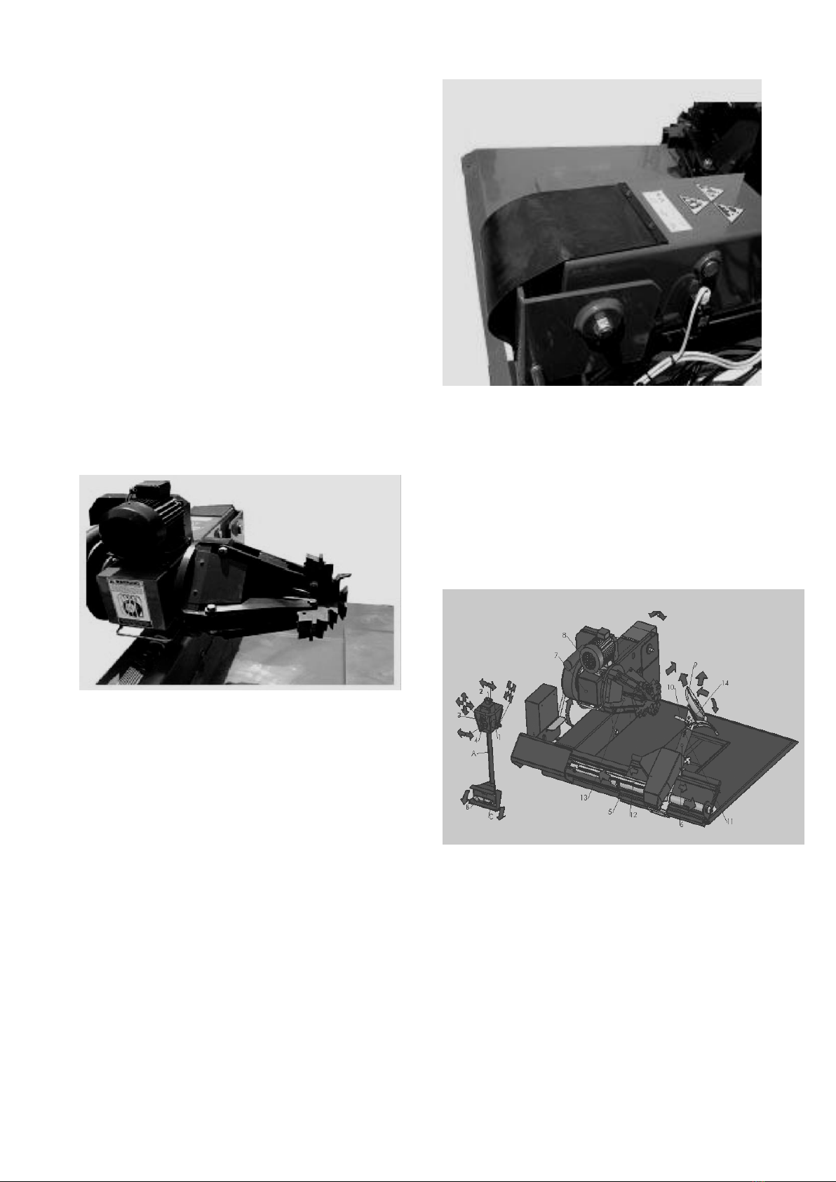
Hook at the lock position
Thanks for you purchase our products. To use this
equipment much better and secure your safety,
you must read this instruction manual and keep it
well. This manual constitutes an integral part of the
products. Please study the warning label and
operation instruction carefully. All of these
information is very important to the safety
operation.
It is the full automatic universal truck tire changer.
The movement of all the work parts is controlled
by a movable console. It can easily
dismount/mount the drop center rim, tubeless
wheel and wheel with ring of truck, agricultural
vehicle and industrial vehicles especially 14"-56"
(Max. wheel diameter is 2300mm and the max.
wheel width is 1100mm)。
This machine can n=only be used to
dismount/mount the tire and not for the other
purpose and we will not be responsible for the
damage of the machine due to the improper use.
Important :The operator should be under the
proper training and with the knowledge of
mechanical, electrical, hydraulic and pneumatic.
Warning!We must dismount/mount after
the wheel is completely deflated!
Warning!It is prohibited to inflate the wheel
when mounted on the machine!
Warning!It needs at least 2person to move the
especially heavy tire!
Warning!The installation and commission of
all the electrical/ pneumatic/ hydraulic parts
must be operated by the professional
technicians.
Warning!You should purchase the wearable
spare parts from the dealers or manufacturer
to guarantee the original parts.
Warning!It is prohibited to move the tool arm
when the hook at the lock position
The manufacturer does not promise to repair
the damage due to the abnormal operation free
of charge.
Technical parameter:
Overall dimension
L .................................................2100~2600 mm
W ..........................................................1900 mm
H ...................................................870~1750 mm
Weight
NW ............................................................987kg
GW:............................................................1252kg
Dual speed gearbox
Speed:..............................1430r/min 2870r/min
Power .......................................................2.4/3kW
Phase ...................................................................3
Power supply ...........................................AC 380V
Noise............................................................≤75 db
Hydraulic motor
DTM590
DUNLOP GARAGE EQUIPMENT

2
Power ..........................................................1.5 kW
Power supply ...........................................AC 380V
Air pressure min/max……………..……...8-10 bar
Applied scope
Rim clamp range …………………………14 ″~ 46 ″
Clamp ring (optional) ………….………...46 ~ 56 ″
Max. wheel diameter……………………...2300 mm
Max. wheel width…………………………...1100mm
Feature:
14-jaw hydraulic chuck(Fig 1):
It can achieve the dual speed and two way rotation
of the chuck. The clamp force can be adjustable.
Fig1 4-jaw hydraulic chuck
2 Clamp jaw(Fig 2):
The design of the clamp jaw can secure the safety
and reliable of clamp.
Fig 2 Clamp jaw
3Movable console(Fig 3):
It can realize the integrated control the move in all
direction.
Fig3 Movable console
4 Hydraulic unit(Fig 4):
Meet the clamp force requirement of varied alloy
rim. This unit is not equipped with the pressure
protective device.
DTM590
DUNLOP GARAGE EQUIPMENT

3
Fig 4 hydraulic unit
5 Mechanical arm(Fig 5):
It is a quick rotation system can help to complete
the detachment of the rim with varied flange from
the tire. The tool head can be removed the tire.
Fig 5 mechanical arm
Accessory:
Standard accessory:
1crowbar(Fig 6):
Remove the hard tire from the wheel
2 Tire clamp with the protection cover and
protection cushion(Fig 7):
Use it when mount/demount the tubeless wheel
and bus wheel.
Fig 7 tire clamp
3 Nylon protective jaw,4pieces(Fig8):
When dismount/mount the aluminum alloy and
light metal rim.
Fig 8 Nylon protective jaw
4 Extension jaw holder, 4pieces(Fig 9)
When dismount the rim of 46~56 ″,you should use
this special accessory.
Fig 6 crowbar
Pin shaft
DTM590
DUNLOP GARAGE EQUIPMENT

4
Fig 9 Extension jaw holder
5 Crowbar 20″ 、 24″ one pc for each(seeing
Fig10)
It is used to remove the retaining ring at the edge
of the rim.
Fig 10 crowbar
Optional accessory:
1 Rim clamp 2pcs(seeing Fig11)
Clamp at the protrude of the rim to detach the rim
from the tire.
Fig 11 Rim clamp
2 Roller:one piece (seeing Fig12)
It is used to mount/demount the tubeless coach
bus tire.
Fig 12 Roller
Unpacking, transportation and
installation:
1 Unpacking
After receiving the machine, remove the package
material. Be careful when remove the tie. Check if
the machine is damaged or the part is missing. If
you have any question to the normal operation,
you can consult the qualified and professional
personnel or agent.
Fig 13 package carton
Warning !Package material such as wood,
plastic bag, polyester board and nails must not
be stored in the area that the children can
reach. It has the potential danger to them.
2 Carriage and hoist:( Fig 14)
DTM590
DUNLOP GARAGE EQUIPMENT

5
Fig14 Carriage and hoist
If the installation is a litter farther needing carriage,
please execute as per the following instruction:
A Regarding the ropes, one is 2X1.5m and the
other is 2X2m. The position to hoist is as per the
Fig14.
B Use the proper lifting device to lift it and the N.T
of the machine is 987kg。
Whenever move the machine, you should care
about safety and meet the condition to hoist.
3 Installation:
Max. overall dimension and installation space
(Fig 15):
Max. height:1750mm width:1900 mm Max.
length:2600 mm
Fig 15overall dimension and installation space
Choose the site safety and convenient to connect
in accordance with the related labor and safety
regulation. The floor to install the machine must be
flat and the enough space should be left around
the machine for the convenience to move and
operate the machine. After the installation of the
machine, use the plug bolt to fix at the 3 fixing
angle iron.(Fig 16)
Fig 16 fixing angle iron
If it is installed outdoors, the machine must be
equipped with the shed to protect the rain.
Electrical and pneumatic
connection:
1 Electrical connection(Fig17)
Fig17 Electrical connection
All the work related to the electrical system must
be executed by the qualified professional
personnel.
Check if the power supply is corresponding with
!It is forbidden to use the machine outdoors
2600mm
1750m
m
DTM590
DUNLOP GARAGE EQUIPMENT

6
the power supply indicated on the nameplate of
the machine.
A Choose the plug as per the local regulation
and the plug must be equipped with the earth
terminator;
B Check if the earth is effective;
C The machine must be connected to the main
circuit with the multi-level circuit breaker switch
complied with CE standard. The distance to
connect is at least 3m.
D Check if the plug of the electrical cabinet (Fig
18)is connected correctly.
Fig 18 Electrical cabinet
E After connect the circuit of the machine, connect
the switch to check if the rotation direction of the
hydraulic unit is corresponding with Fig 19;
Fig 19 Construction drawing A
F If the rotation direction of the oil pump motor is
reverse, exchange any two phase at the power
plug;
G If the running of the machine is abnormal, you
should immediately switch off the power switch(No
15 in Fig 19 ) and check the reason of the
troubleshooting and repair.
The manufacturer will not be responsible for
the damage due to the above reversal connect
of power cable
2 Pneumatic connection
As per Fig 20
Fig20 Air regulator
Safety protection label:
When operate, you should pay attention to the
warning label on the machine.
A Warning the drop off of the wheel;
B Warning the tool head may rotate.
C Warning the chuck may rotate
C Warning the tilt of the chuck arm and tool arm
外接气源接头
DTM590
DUNLOP GARAGE EQUIPMENT

7
E Warning the electrical shock
If you lose or damage one or more warning label
above mentioned ,you should order the lost
warning labels from our company and note the
relevant code for repair.
2 .tyre changer with the following
safety protects :
1) Chuck protective sheet(Fig 21)
Four metal protective sheets are used to protect
the disk inside when the jaws open. Another
function of it is to prevent the inward reach of the
human body or the tools.
Fig 21 Chuck protective sheet
2)Chuck protective rubber sheet(Fig22)
It is used to prevent the reach of the human body
or the tools inwards from the rear of the chuck
arm.
Fig22 Chuck protective rubber sheet
3) Safety micro-switch(Fig24)
It is the electrical control device. When the chuck
arm falls, it will immediately stop.
Warning!When exist the trouble shooting, if any of
the above safety devices does not work, please
repair at once.
Fig23 structure B
DTM590
DUNLOP GARAGE EQUIPMENT

8
Fig24 Safety micro-switch
Operation and machine structure
instruction
Switch in reference to Fig 23
Manual switch control to control
1. the movement of mechanic arm and tool head
control
2. movement of mechanical arm
3. movement of carriage and tool arm
4. open/ close of jaw
Pedal control:
B. chuck rotation pedal(clockwise)
C. chuck rotation pedal(counterclockwise)
5. Carriage
6. Mechanical arm
7. Chuck arm
8. Jaw
9. disk
10. tool head position joystick
11. mechanical arm position joystick
12. mechanical arm movement oil tank
13. tool arm
14. tool
15. power switch
16. hydraulic gauge
17. oil level indicator
18. hydraulic pressure adjust valve
19. 9 disk
10. tool head position joystick
11. mechanical arm position joystick
12. mechanical arm movement oil tank
13. tool arm
14. tool
15. power switch
16. rotation direction indicator
17. oil level indicator
18. hydraulic pressure adjust valve
19. pump station rotation direction indicator
the changer is an universal tire changer applied to
dismount/mount 14"-56" rim of truck, agricultural
trailer , extractor and shovel loader. It has a
mechanical arm(6)and a full automatic carriage
(5). The movement of the mechanical arm and
the carriage are controlled by the console.
Commission
Function check
1.Check if the movement of the mechanical arm
(6)and tool head (9)is correct.(Fig 23 and
Fig25)
Fig25 Structure C
● Pull upward the switch1 (Fig25 1a ), the
mechanical arm must go upwards
● Pull downward the switch1(Fig25 1b), the
mechanical arm must go downwards
外接气源接头
Throttle valve
Air supply connect
DTM590
DUNLOP GARAGE EQUIPMENT

9
● Pull rightward the switch1(Fig25 1c), the tool
head must rotate counterclockwise by 180°
● Pull leftward the switch1(Fig25 1d), the tool
head must rotate clockwise by 180°
● Pull rightward the switch 2(Fig 23 )the tool
arm must move rightwards.
● Pull leftward the switch 2(Fig 23 )the tool arm
must move leftwards.
2 Check if the movement directions of the carriag
(5)and tool arm(7)is correct(see Fig 23):
● Push leftward switch 3, carriage move
leftward.
● Push rightward switch 3, carriage move
rightward.
● Push upward the switch 3, the tool arm move
upward
● Push downward the switch3, the tool arm
move downward
3 Check if the function of the center chuck is
correct (see Fig 22):
● Push the switch4 leftward, the chuck will
open.
● Push the switch4 rightward, the chuck will
close.
● Step the pedal switch at the b side,the chuck
will rotate clockwise.
● Step the pedal switch at the c side,the chuck
will rotate counterclockwise
4 Check the vertical movement of the tool arm and
the rotating function of the tool
hea
Fig 26 Valve mounting board
Adjust the throttle valve of the valve mounting
board(Fig 26), the tool arm rising speed will
increase or decrease.
Fig27 direction switching cylinder
Adjust the throttle valve of the direction switching
cylinder (Fig 27) to increase or decrease the
rotating speed of the direction changing device of
the tool head.
5 Tire clamp function:
Adjust the hydraulic clamp force of the chuck:
We can change the clamp force of the chuck by
adjusting the pressure decrease valve rotation
handle of the hydraulic power unit. The pressure
ranges 130 bar, which can be displayed via
hydraulic gauge. When dismount/mount the light
alloy rim or the rim of very thin ,you should
Throttle valve
Throttle valve
DTM590
DUNLOP GARAGE EQUIPMENT

10
decrease the pressure. The standard work
pressure is 130 bar.
Chuck with 4 jaws can clamp any rim of 14~56″. To
the rim of 42~56″, we provide 4 extension rod can
be mounted on the jaw (See Fig 9)
To the wheel of the diameter less than 800mm and
exceed 1500mm, you should insert the pin into the
second hole. (See the 11 in Fig23)
For the aluminum rim, we can provide 4 nylon
protective jaw mounted on the clamp. See Fig28.
Fig 28 Mount the nylon protective cover
The nylon protective cover
should be mounted on the
aluminum alloy rim (Fig28)
Note: When mount/dismount the aluminum alloy
rim difficult to handle,you can place 2pins in the
hole of the terminal of the rim to avoid the nylon
protective cover sliding on the rim. See Fig 8
Dismount/mount wheel:
wheel tubeless/ ring less coach car wheel
Completely deflate the wheel to be changed and
place on the carriage. Pay attention to the
construction of the rim. The small slope
termination rim should be outside, that is far away
from the chuck. Start the machine, use 4claws
clamp the center hole or any other suitable
position. Rise up the tool arm to the suitable height.
Move the carriage to the side far away from the
chuck. Contact the press disk on the tool head
against the termination of the tire. Continue
rotating the wheel and move the carriage towards
the tire to make the press disk be contacted with
the tire and then continue pressing for a little
distance. You can observe that there will be some
clearance at the position of the tire and rim
pressed by the press disk. Spread evenly a layer
of Vaseline Oil in the clearance. Continue rotate
and spread the oil until all the contact plane
between the rim and tire is spread with oil. Move
steeply rightward the carriage to make the press
disk about 200mm from the termination of the tire.
Rise up the mechanical arm and rotate the tool
head and move the carriage to the other side of
the tire and lower the mechanical arm and rotate
the chuck and steeply move the carriage to make
the press disk on the termination of the tire until
the entire tire is detached from the rim.
Mount the tire
A Use the chuck to clamp the rim and fix the tire
on the flange of the rim and keep it far away from
the chuck.
B Place the tire on the carriage and move the
carriage and rotation tool arm to insert the tire
pliers into the side of the tire hole. Rotate the
chuck to rise up the tire and use the press disk to
press the right termination of the tire to move the
tire leftwards to the proper position. At this
moment, one flange of the tire has been mounted
in the rim. Take off the tire pliers and continue
pressing the tire leftwards until the right side of the
tire into the right side of the rim and stop rotating
the chuck and mount the tire pliers on the press
disk. Rotate the chuck clockwise for a cycle to
complete the mount of the tire and detach the tire
pliers.
DTM590
DUNLOP GARAGE EQUIPMENT

11
Fig 29
Engineer vehicle tire mount/dismount
A Place the wheel on the carriage and move the
carriage.
B Clamp the chuck at the suitable position and rise
up the tool arm and rotate the wheel counter
clockwise. Use the press disk on the tool head to
push and press the retaining ring and mount the 2
rim clamps as shown in Fig27.
C Use the press disk on the tool head to continue
press the tire making it close to the termination of
the retaining ring. The tire rotates for 2cycles and
then move the carriage leftwards. This process
needs 15minutes for the bind of the tire and rim
due to long time of compression each other. This
process should be stopped until the right side of
the tire is completely detached from the rim and
detach the rim clamp.
D Use the crowbar to prized up one end of the ring
and fix it with the press disk. Rotate the chuck to
take off the ring and continue press the rum and
take off the sealing ring. Rotate the chuck and use
the press key to pull the retaining ring and take off
the rim and retaining ring.
E Move the carriage to the left side and use the
press disk to press the termination of the tire.
When you see the tire is detached from the rim,
rotate the tool arm to place the tire on the tire
carriage and move rightward the carriage to
detach the tire from the rim.
F Mount the wheel in reference to the above
procedure.
Warning! The movement of the especially heavy
wheel, we need at least 2persons!
Troubleshooting and repair
Troublesh
ooting
reason
solution
Chuck
does not
rotate
1.Power plug not
plugged into the
socket
2.The wiring of the
plug not correct
3.Power supply
voltage not
corresponding with
the requirement.
4 Main switch not
connected
5 Fuse blown.
1.Check if the
power plug has
been plugged
into the socket
effectively.
2.As per 2~3,
see the solution 1
3.Connect the
main switch.
4.Change the
fuse
The
rotation
force of the
chuck not
enough
1. Choice of the
voltage not correct
2. Driven belt is
loose
3. Capacity of the
fuse is small.
1. Check if the
power supply is
corresponding
with the ones on
the name plate
on the machine.
2. Adjust the
tension of the
belt;
3. Change fuse
Hydraulic
jaw can not
clamp the
rim firmly
1. Thermal-magnet
switch not connect
2. Work pressure of
the hydraulic valve is
adjusted too low.
3. Hydraulic
system pressure too
1. Check if the
rotation of the oil
pump motor is
correct
2. Adjust the
work pressure of
the one way
DTM590
DUNLOP GARAGE EQUIPMENT

12
low.
valve
3. Settle the
troubleshooting
of the hydraulic
system.
Hydraulic
part of
hydraulic
system
and
machine
can not
work
(carriage,
tool arm
and jaw)
1. Rotation
direction of the
hydraulic oil pump
motor is not correct.
2. Thermal
over-load protective
device break
3. 24V fuse broken
1. Exchange
fuse in the plug;
2. Connect the
thermal over load
protector
3. Change fuse
The other technical troubleshooting should be
setled by the professional technicians authorized!
Maintenance
The operators should always clean and
maintenance the machine.
The operators should maintenance the
equipments in reference to the methods described
in the instruction manual provided by the
manufacturer.
Before clean and maintenance, you should cut off
the power/pneumatic supply .
Mechanical maintenance
Periodically clean the chuck and carriage and
lubricate carefully with gun.
Check the oil level of the hydraulic power unit. Add
the wear resistance hydraulic oil with the viscosity
required.
Transportation
The requirement to the rope or the methods to
hoist, see the Fig15 of this manual.
Note:
Pull out the power plug and keep well the power
cord if long time no use of machine.
Repair
No matter which troubleshooting, handle as per
the methods listed on P12. The other
troubleshooting should be handled by the
professional personnel or contact with the dealer
or the manufacturer..
Remind:After the troubleshooting
happens and need repair, provide
the following information
A model of machine; B series number; C detail of
troubleshooting
Knowledge and note for the
repair and maintenance
Before any maintenance and repair, you should
cut off the power supply and air source to prevent
the accident to the operator of equipment and
the person responsible for the equipment should
periodically check and survey.
1. The power supply must be grounded reliable.
2.The oil cup of the air regulator should be filled
with the oil periodically and the oil feeding should
be adjusted. When the pneumatic part active for
4times, one drop of oil will be feed.
3、You should secure the air supply pressure to
be 8-10bar ,or the machine can not operate
normally.
4、Hydraulic power unit should use the
wear-resistant hydraulic oil N46. You should not
adopt the hydraulic oil of different chemical.
Change the hydraulic oil one time for the total time
to use the hydraulic oil reaches 600—800hours to
DTM590
DUNLOP GARAGE EQUIPMENT

13
prevent the abnormal operation of the hydraulic
parts due to the deteriorate of oil.
5、Feed the lithium grease to secure the
lubrication of the rotation parts periodically (at
least once per 3months).
6. Weekly check connect part to prevent loosing
causing troubleshooting such as oil leakage.
7. Keep the hydraulic tank from moving to the limit
position to prolong the life of the sealing parts
inside.
8. For gearbox, change the grease(mix of lithium
grease and motor oil)once half a year.
9.After each operation, timely cut off the power
supply of electrical/air to prolong the life of the
machine and save energy.
10、At the end of one day or shift, you should clean
the machine to prevent the rust of the surface of
the machine causing the come off of the coat.
11、Pay attention to the clean of each guide rail
and spread the grease to keep the lubrication well.
DTM590
DUNLOP GARAGE EQUIPMENT

14
Pneumatic scheme
Air regulator
Pressure gauge
Valve
Valve
Valve
Tool head lift
cylinder
Tool head
rotating cylinder
Tool head bracket
lift cylinder
Counter
clockwise
Clockwise
DTM590
DUNLOP GARAGE EQUIPMENT

15
Hydraulic scheme
pump motor:Y90-4-1.5-220V/380V;
rated working pressure:15MPa
Fig31
1pump station 2solenoid valve 3tool bracket control oil tank
4trail control oil tank 5lift oil tank 6H solenoid valve 7safety
valve 8oil guide 9pressure gauge 10main clamp control oil tank
DTM590
DUNLOP GARAGE EQUIPMENT

16
Control voltage:DC24V; motor, oil pump and valve plate is designed to be separated.
Power switch
Pump motor
Short circuit protection
Main shaft motor
Control transformer
DTM590
DUNLOP GARAGE EQUIPMENT

17
3 phase electrical cabinet terminator layout
DTM590
DUNLOP GARAGE EQUIPMENT
Table of contents
Popular Tyre Changer manuals by other brands

Corghi
Corghi A 9824 TI Operator's manual

Glomstad Motor
Glomstad Motor GM-U200 PRO Use and maintenance manual

Sicam
Sicam JUMBO TCS52 NW Original instructions

Draper
Draper 16395 instructions

WERTHER INTERNATIONAL
WERTHER INTERNATIONAL TITANIUM 200/22 Instruction and maintenance manual

Dannmar
Dannmar T-100 Installation and operation manual