1 695 105 431 2010-02-16|Robert Bosch GmbH
Product description | TCE 4225 | 25 en
3.6 Description of function
Below are reported the main functions of the listed
components of the TCE 4225:
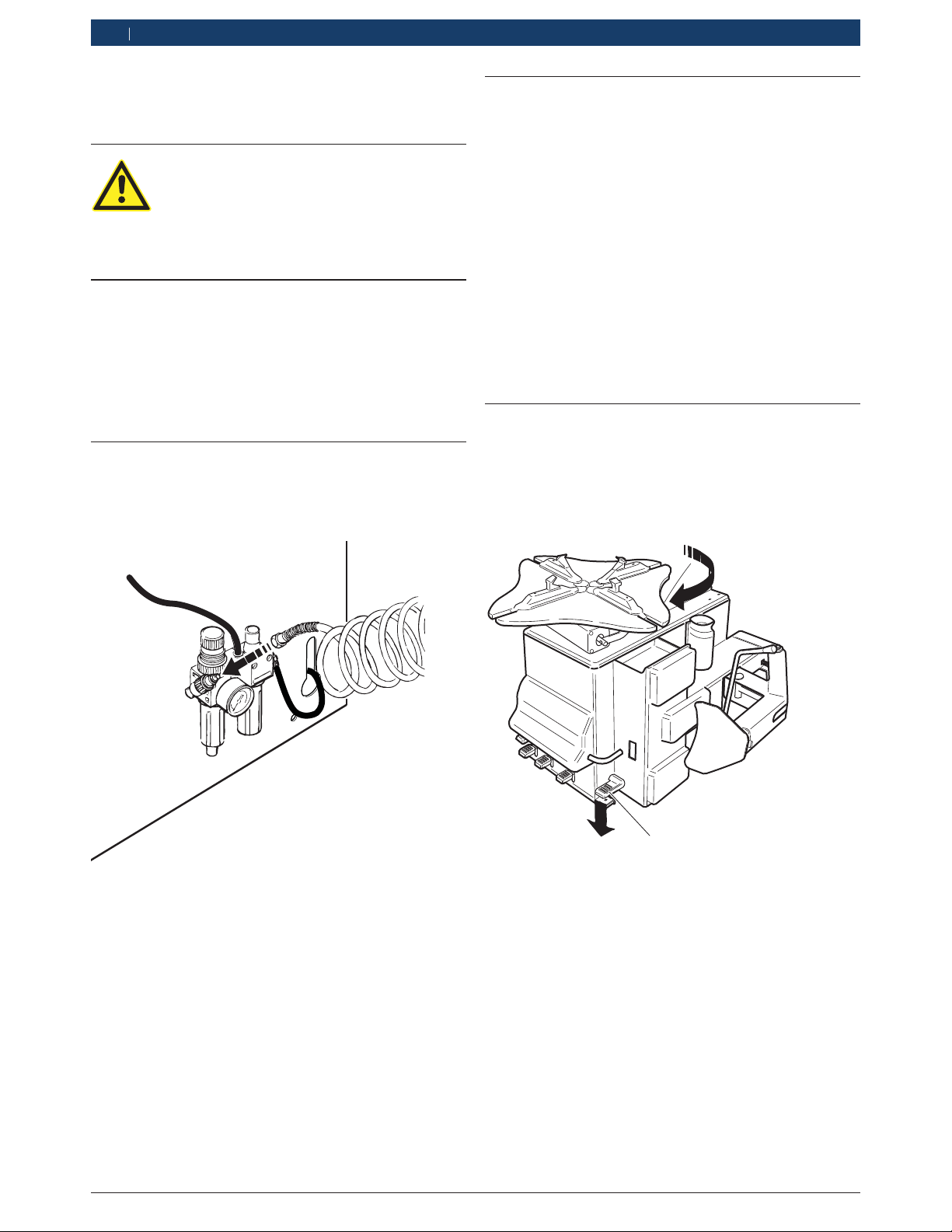
3.5 Description of unit
On the TCE 4225 there are rotating and mo-
ving parts that could injure fingers and arms.
652006-01_Mi
2
4
3
1
5
7
8
13
12
14
15
18
17
16
6
9
10
1
11
21
24
22
19
20
23
Fig. 1: TCE 4225
Pos. Name Function
1 Locking flange rotation pedal Locking plate rotation:
clockwise (press down the pedal).
counter-clockwise (lift the pedal from bottom to top).
2 Bead breaker pedal Bead breaking arm activation.
3 Locking jaw pedal Opening and closing of the locking plate jaws.
4 Inflation pedal Operation of the automatic inflation device for tubeless tires and inflation pipe.
5 Bead breaking arm Bead breaking of the tire from the rim.
6 Bead breaking arm lever Positioning of the bead breaker blade.
7 Bead breaker blade Tire pressing for bead breaking operation.
8 Antiabrasive supports Tire support for bead breaking operations.
9 Column Horizontal jib arm and mounting tool support.
10 Cantilever horizontal arm Horizontal positioning of the mounting tool.
11 Locking knob Cantilever arm locking.
12 Vertical sliding rod Vertical positioning of the mounting tool.
13 Locking lever Locking of the vertically sliding rod.
14 Mounting tool Mounting and demounting of the tire from the rim
(with the help of the bead lifting lever).
15 Sliding roller Inserted in the mounting tool compartment, to avoid any friction between the
rim and mounting tool during the tire dismantling and assembly phases
For the alloy rims, a special plastic protection is arranged.
Locking plate, locking and rotation device (clockwise
and counter-clockwise) of the rim, pneumatically
driven by 2 cylinders, made of 4 movable lanes with
locking jaws for the internal and external locking of
the rim.
Column switch group, made up of a column switch
which supports the components necessary to dis-
mantle (and re-assemble) the tire from the rim: flag
horizontal arm (with locking knob), vertical sliding
rod (with locking lever), mounting tool to dismantle
(and re-assemble) the tire from the rim, with the aid
of the bead lifting lever.
Bead breaker, for the bead breaking of the tire from
the rim; it is made of the bead breaking arm pneu-
matically operated by a double effect cylinder, lever
for the arm positioning, antiabrasive supports for rim
support during bead breaking phases.
Pedal box, comprehends control pedals of the equip-
ment (locking flange rotation pedal, bead breaking
pedal, locking jaws pedal, inflation pedal).
Automatic inflation device for tubeless tires, made
by a compressed air circuit and an instantaneous
opening valve operated by the inflation pedal (the air
comes out from holes on the jaws, in order to seat
perfectly the bead of a tubeless tire).