Athena C10 Series User manual

ATHENA CONTROLS, INC.
5145 Campus Drive
Plymouth Meeting
PA 19462 U.S.A.
Tel: (610) 828-2490
Fax: (610) 828-7084
AthenaControls.com
Controller
Indicator
Transmitter
1/32 DIN - 48 x 24
C10 line cc
User manual • M.I.U.C10-1/02.06 • Cod. J30-478-1AC1 SEA
UL
CUS
LISTED

Controller
Indicator
Transmitter
1/32 DIN - 48 x 24
C10 line cc
274.8
UL
CUS
LISTED

2
information
cc
NOTES
ON ELECTRIC
SAFETY AND
ELECTROMAGNETIC
COMPATIBILITY.
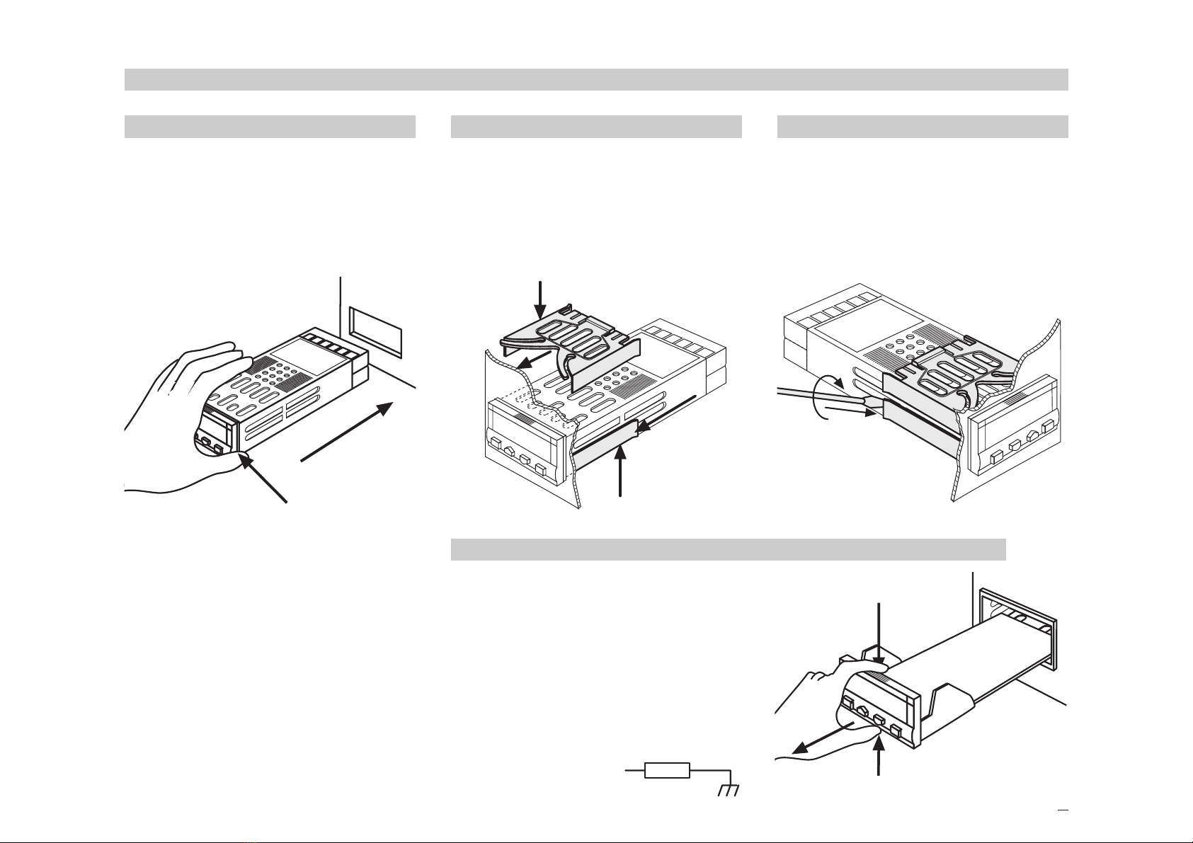
Please, read carefully these instructions before proceeding with
the installation of the controller.
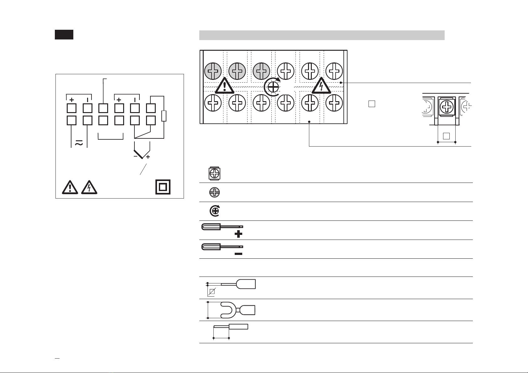
Class II instrument, rear panel mounting.
This controller has been designed with compliance to:
Regulations on electrical apparatus (appliance, systems and installa-
tions) according to the European Community directive 73/23 CEE amend-
ed by the European Comunity directive 93/68 CEE and the Regulations
on the essential protection requirements in electrical apparatus EN 61010-
1 (IEC 1010 - 1) : 90 +A1:92 + A2:95.
Regulations on Electromagnetic Compatibility according to the
European Community directive n089/336/CEE, amended by the European
Community directive n° 92/31/CEE and the following regulations:
Regulations on RF emissions
EN50081 - 1 residential environments
EN50081 - 2 for industrial environments
Regulation on RF immunity
EN500082-2 for industrial equipment and system
It is important to understand that it’s responsibility of the installer to ensure
the compliance of the regulations on safety requirements and EMC.
The device has no user serviceable parts and requires special equipment
and specialised engineers. Therefore, a repair can be hardly carried on
directly by the user. For this purpose, the manufacturer provides techni-
cal assistance and the repair service for its Customers.
Please, contact your nearest Agent for further information.
All the information and warnings about safety and electromagnetic
compatibility are marked with the Bsign, at the side of the note.

3
Table of contents
TABLE OF CONTENTS 1INSTALLATION...........................................................................................................................Page 4
2ELECTRICAL CONNECTIONS.....................................................................................Page 8
3PRODUCT CODING..............................................................................................................Page 14
4OPERATIONS..............................................................................................................................Page 18
5AUTOMATIC TUNE...............................................................................................................Page 28
6TECHNICAL SPECIFICATIONS...................................................................................Page 29
Main universal input
Control Alarms Retransmission
Resources
OP1
PV
OP2
OP4
(option)
Setpoint
Operating mode
PV
C10
1Single OP1 OP2 OP4
output
2Single OP2 OP1 OP4
output
0Indication OP1 OP2 OP4
only
Modbus RS485
Parameterisation
Supervision
Fuzzy tuning
with automatic selection
One shot
Auto tuning One shot
Natural frequency

4
1 - Installation
1INSTALLATION
Installation must only be carried
out by qualified personnel.
Before proceeding with the instal-
lation of this controller, follow the
instructions illustrated in this man-
ual and, particularly the installation
precautions marked with the B
symbol, related to the European
Community directive on electrical
protection and electromagnetic
compatibility.
B
To prevent hands or metal touch-
ing parts that may be electrically
live, the controllers must be
installed in an enclosure and/or in
a cubicle.
1.1 GENERAL DESCRIPTION
IP 20 Termination Unit
EN61010 - 1 (IEC1010 - 1)
Product code label
Sealin front panel gasket
Mounting clamps
Front panel
IP65 protection
EN 60529 (IEC 529)
Panel surface

5
1 - Installation
1.2 DIMENSIONAL DETAILS
48 mm
1.89 in
25 mm
0.99 in
120 mm
4.72 in
20 mm max
0.79 in max
1.3 PANEL CUT-OUT
65 mm min
2.56 in min
42 mm min.
1.65 in min.
22.2+0.3 mm
0.87+0.01 in
45+0.6 mm
1.78+0.023 in

6
1 - Installation
Special conditions
MAltitude > 2000 m
TTemperature >50°C
%Rh Humidity > 95 %
PConducting atmosphere Use filter
Warm up
Use forced air ventilation
Use 24V~supply version
Suggestions
Forbidden Conditions D
CCorrosive atmosphere
EExplosive atmosphere
Operating conditions
MAltitude up to 2000 m
TTemperature 0…50°C
%Rh Relative humidity 5…95 % non-condensing
1.4 ENVIRONMENTAL RATINGS B

7
1 - Installation
1.5.1 INSERT THE INSTRUMENT
1Prepare panel cut-out
2Check front panel gasket posi-
tion
3Insert the instrument through
the cut-out
1.5 PANEL MOUNTING
1.5.2 INSTALLATION SECURING
1Position the mounting clamps
2Push the mounting clamps
towards the panel surface to
secure the instrument
1
3
2
1.5.3 CLAMPS REMOVING
1Insert the screwdriver in the clips
of the clamps
2Rotate the screwdriver
1
2
1.5.4 INSTRUMENT UNPLUGGING B
1Push and
2pull to remove the instrument
Electrostatic discharges can dam-
age the instrument
Before removing the instrument the
operator must discharge himself
to ground
1
1
2
1
2
1
1MΩ

8
2 - Electrical connections
2ELECTRICAL
CONNECTIONS
2.1 TERMINATION UNIT B
12 screw terminals
Option terminals
Holding screw 0.5 Nm
Positive screw driver PH1
Negative screw driver 0,8 x 4 mm
Recommended wire terminal leads
Pin connector q1.4 mm - 0.055 in max
Ø
Fork-shape AMP 165004 Ø 5.5 mm - 0.21 in
L
Stripped wire L 5.5 mm - 0.21 in
123456
789101112
0,5
Nm
Rear
terminal
cover
Cable size
0,5…1,5 mm2
(22 a 16 AWG)
5.7 mm
0.22 in
mA
mV
1
TC
OP1
23456
78910 11 12
b
B
A
RTD
LN
NO C
RS485
(OP4) OP2 - L
+18V— OUT
F50- 474 1A1C1

9
2 - Electrical connections
PRECAUTIONS B
Despite the fact that the instrument
has been designed to work in an
harsh and noisy environmental
(level IV of the industrial standard
IEC 801-4), it is strongly recom-
mended to follow the following
suggestions.
A
All the wiring must comply with the
local regulations.
The supply wiring should be rout-
ed away from the power cables.
Avoid to use electromagnetic con-
tactors, power relays and high
power motors nearby.
Avoid power units nearby, espe-
cially if controlled in phase angle
Keep the low level sensor input
wires away from the power lines
and the output cables.
If this is not achievable, use shield-
ed cables on the sensor input, with
the shield connected to earth.
2.2 RECOMMENDED ROUTING OF WIRES B
123456
789101112
LN IN
Conduit for supply and output cables
Conduit for low level sensor cables
AB
DEC
123456
789101112
LN IN
AB
DEC
A= Supply
B= Outputs
C= Analog inputs
D= Analogue output
Serial communications
E= SSR drive output

10
2 - Electrical connections
2.3 TYPICAL INSTRUMENT WIRING B
6
V~
Supervisory
Supply V~
V~
Retransmission
4…20mA
L
N
DC voltage
Thermocouple
Current
2.5 Ωexternal
shunt resistor
Coil of the load
contactor
Fuse
Power
supply
switch
OP2
OP1
V~
Fuse 0.2 A T
18V
Pt100
2 wire
transmitter
Load Solid
state
relays
PV
54321
121110987
A
B
B
0P4
RX/TX
[6]
RS485
[5]
[4]
Notes:
1] Make sure that the power supply
voltage is the same indicated on
the instrument.
2] Switch on the power supply only
after that all the electrical con-
nections have been completed.
3] In accordance with the safety reg-
ulations, the power supply switch
shall bring the identification of the
relevant instrument. The power
supply switch shall be easily
accessible from the operator.
4] The instrument is protected with
a 0.2 A~T fuse. In case of fail-
ure it is suggested to return the
instrument to the manufacturer
for repair.
5] To protect the instrument internal
circuits use:
- 2 A~T fuses for Relay outputs
- 1 A~T fuses for Triac outputs
6] Relay contacts are already pro-
tected with varistors.
Only in case of 24 V ~induc-
tive loads, use model A51-065-
30D7 varistors (on request)

11
2 - Electrical connections
2.3.1 POWER SUPPLY B
Switching power supply with mul-
tiple isolation and internal fuse
• Standard version:
nominal voltage:
100 - 240V~(- 15% + 10%)
Frequency 50/60Hz
• Low Voltage version:
Nominal voltage:
24V~(- 25% + 12%)
Frequency 50/60Hz
or 24V– (- 15% + 25%)
• Power consumption 1.6W max
0.2A included fuse
Supply
LN
1 2
2.3.2 OP1 OUTPUT B
2.3.3 OP2 OUTPUT B
A] Single relay output
• NO contact for resistive load of
up to 2A / 250V~max.
• Fuse 2A~T
(IEC 127)
B] Triac Output
• NO contact for resistive load of
up to 1A / 250V~max.
• Fuse 1A~T
(IEC 127)
• Logic output, not isolated
0...5V–, ±20%, 30mA max
Varistor for
inductive loads
24V~ only
Fuse
Coil of the
load contactor
3 4
3 4
Varistor for
inductive loads
24V~ only
Fuse
Coil of the
load contactor
Load Solid
state
relay 10 11

12
2 - Electrical connections
2.3.4 PV CONTROL INPUT B
• Connect the wires with the
polarity as shown
• Use always compensation cable
of the correct type for the ther-
mocouple used
• The shield, if present, must be
connected to a proper earth.
• If a 3 wires system is used, use
always cables of the same
diameter (1mm2min.)
(line 20 Ω/lead maximum resis-
tance)
• When using a 2 wires system, use
always cables of the same diam-
eter (1,5mm2min.) and put a
jumper between terminals 5 and 6
AWhen the distance between the
controller and the sensor is 15
mt. using a cable of 1.5 mm2
diameter, produces an error on
the measure of 1°C.
For L J K S T thermocouple type
wire resistance
150Ωmax
For PT100 resistance thermometer
For 3 wires only
20 Ω/lead maxi-
mum resistance
For ∆T (2 x RTD Pt100) Special
Use wires of the
same length and
1.5 mm2size.
20 Ω/lead maxi-
mum resistance.
R1 + R2 must be < 320Ω
5 6 12
ABA
R1 R2
5 6 12
BBA
5 6
For mA, mV and V
External shunt
2.5Ω
Rj >10MΩ
With 2 wire transducer
With 3 wire transducer
external
shunt
2.5Ω
Transducer
PV
18Vdc
9 5 6
18Vdc
4…20mA
external
shunt
2.5Ω
Transducer
PV
9 5 6
mV
mA
5 6

13
2 - Electrical connections
2.3.5 OP4 OUTPUT (option) B
2.3.6 SERIAL COMMUNICATIONS (option) B
PV retransmission
• Galvanic isolation
500V~/1 min.
• 0/4...20mA, 750Ω/ 15V– max
• Galvanic isolation 500V~/1 min
• Compliance to the EIA RS485
standard for Modbus/Jbus
APlease, read the user
instructions on the
“C10 controller
MODBUS/JBUS protocol”
RX
TX
7 8
Load
7 8
mA

14
3 - Product coding
3PRODUCT
CODING
The complete code is shown on
the instrument label. The informa-
tions about product coding are
accessible from the front panel by
mean of a particular procedure
described at section 4.2.2 page 19
3000
L
C D
M N
B
P/N
S/N
V~(L-N) : 100 ÷240V 50/60 Hz - 1.6W
; C10-3000-0300
: A0A-9809/0013
Made in Italy
IND. CON. EQ.
23 FA
UL
CUS
LISTED
Instrument label
Basic product code (hardware)
Configuration code (software)

15
3 - Product coding
Option 1 DOption 2
Not provided 0
Not provided
6
Transmitter Power Supply (PS)
RS485
Modbus/Jbus protocol 0
Not provided
6
Transmitter Power Supply
C
0
0
5
5
Option 3 E
Not provided 0
Front Bezel Color [2] G
Dark Grey (standard) 0
Beige 1
Output 1 [1] B
Relay 0
Triac 3
Power supply A
100 - 240V~(-15% + 10%) 3
24V~(-25% + 12%) or 24V–(-15% + 25%) 5
Line 10C
3.1 MODEL CODE
The product code indicate the spe-
cific hardware configuration of the
instrument, that can be modified
by specialized engineers only.
Line Basic Accessories
C10 A B C D -E F G H
7
Transmitter PS + Retransmission 0
Model:
Logic
Logic
Output 2 [1]
Standard English/Spanish manual
User manual
3
F
Standard resistor
Standard resistor
0/4-20mA Input Shunt Resistor [2]
Dark Grey High accuracy resistor 2
Beige High accuracy resistor 3
1
0
H
DIN rail without display (requires CD option code 50 or 56) 2
Mounting (DIN rail mounting does not include UL)
Panel (standard)
DIN rail with display
Notes
[1] Relay SPST N.O. 2A/250V;
Triac 1A/250V; Logic 5V 30mA
[2] Standard shunt resistor without field
calibration will provide 1.10% input
accuracy for 0/4-20mA input
High accuracy shunt resistor with-
out field calibration will provide
0.20% input accuracy for 0/4-20mA
input
Either shunt resistor with field cali-
bration will provide 0.10% input
accuracy for 0/4-20mA input

16
3 - Product coding
3.2 CONFIGURATION CODING
The configuration code consists of
4 digits that identify the operat-
ing characteristic of the controller,
as chosen by the user.
Section 4.5 at pag. 26 reports the
instructions how to set a new con-
figuration code.
The configuration code can be dis-
played on the front panel, follow-
ing the instructions at pag 19 sec-
tion 4.2.2.
I L M N
2002
TC T Cu-CuNi 4
TC K Cromel -Alumel IEC584 5
TC S Pt10%Rh-Pt IEC584 6
Input type and range I
DC input 0…50 mV, linear
TR Pt100 IEC751 0
7
DC input 10…50 mV, linear 8
Custom input and range
TR Pt100 IEC751 1
9
TC L Fe-Const DIN43710 2
-328…752 °F
TC J Fe-Cu45% Ni IEC584 3
32…2192 °F
32…2912 °F
-99.9…572.9 °F
-328…1112 °F
32…1112 °F
32…1112 °F
-200 …400 °C
0…1200 °C
0…1600 °C
engineering units [1]
-99.9…300.0 °C
engineering units [1]
-200…600 °C
0…600 °C
0…600 °C
2 alarms
indicator 4
Output configuration
5
Control mode L
Alarm AL1 on OP1/ alarm AL2 on OP2
P.I.D. 0
Alarm AL1 on OP2/ alarm AL2 on OP1
Control OP1 / alarm AL2 on OP2
1
Control OP2 / alarm AL2 on OP1
On - Off 2
Control OP1 / alarm AL2 on OP2
3
Control OP2 / alarm AL2 on OP1
Type of control and safety M
Reverse (AL1 active low)
Direct (AL1 active high) 0
Safety 0%
1
Safety 0%
Reverse (AL1 active low)
Direct (AL1 active high) 2
Safety 100%
3
Safety 100%
Note
[1] 0...20 & 4...20mA with provided external 2.5 Ωresistor.

17
3 - Product coding
A
If, when the controller is pow-
ered up for the first time, the dis-
play shows the following mes-
sage
it means that the controller has
not been configured yet.
The controller remains in stand-by
until the configuration code is set
correctly (see chapter 4.6 pag 26).
Alarm 2 type and function N
Not active 0
Sensor break alarm 1
Absolute 2
active high
3
active low
Deviation [1] active high 4
active low 5
Deviation
band [1]
active out (of the band) 6
active in (the band) 7
Note
[1] Choice not available when the controller has been configured as 2 alarms
indicator ( L digit assigned to 4 or 5)

18
4 - Operations
4OPERATIONS 4.1 KEYPAD COMMANDS AND DISPLAY
Values
modification
Enter key for
selection and
value setting
confirmation
Menu
access
OP1 output ON
(red)
OP2
output
ON
(red)
Tuning
in progress
(green) • PV control input
(operator mode)
(in engineering units)
when the measured
value is greater than
sensor high range
when the measured
value is less than the
sensor low range
•Code and/or value of
the Parameter
(programming mode)

19
4 - Operations
4.2 DISPLAY
When the display operation is
selected, the controller presents
automatically all the most impor-
tant parameters and configuration
information.
During the operation, the para-
meters values cannot be modi-
fied by the user
After 2 sec from the end of the
operation, the controller flashes the
display and returns to the normal
operating conditions.
4.2.1 OF THE PROCESS
VARIABLES
4.2.2 OF THE CONFIGURATION
CODES
270.5
274.8
Unit
s.p.
Out
63.0
°C
Operator
mode
Engineering
units
[1]
Setpoint
Control
output
[2]
Note
[1] See table page 27
[2] This display is not presented if the
instrument has been configured as
an On - Off controller
2002
274.8
Unit
Conf
rel.
00A
°C
Hard
3000
Operator
mode
Engineering
units
[1]
Basic
product code
(see page 15)
Configuration
code
(see page 16)
Software
release
number
after
0,5 sec. after
0,5 sec.
Example:
C10 - 3000 - 2002 / Release 00A
Other manuals for C10 Series
1
Table of contents